nilan Comfort 200 Top Installation Instructions Manual
Hide thumbs
Also See for Comfort 200 Top:
- Installation instructions manual (48 pages) ,
- User manual (28 pages) ,
- Installation instructions manual (32 pages)

Related Manuals for nilan Comfort 200 Top


Summary of Contents for nilan Comfort 200 Top
- Page 1 INSTALLATION INSTRUCTIONS CTS602 LIGHT BY NILAN Comfort 200 Top Version 4.10 - 09.08.2024 M24 Comfort 200 Top_GB...
-
Page 2: Table Of Contents
Introduction........................................... 4 Documentation........................................ 4 Unit type ..........................................5 Product description ......................................5 Dimensional drawing Comfort 200 Top ..............................6 Functional block diagram ....................................7 Accessories ........................................... 8 Electrical pre-heating element for frost protection of the unit ......................8 Electrical after-heating element for duct installation ..........................8 Water after-heating element for duct installation ........................... - Page 3 Electrical connections accessories .................................16 User selection 1 ......................................16 User selection 2 ......................................17 Modbus ...........................................17 Fire thermostat / external fire automation system ..........................18 EM Box (damper option)....................................19 DTBU (damper option) ....................................20 External pre-heating element ..................................21 Installation of expansion PCB on CTS602 Light circuit board ......................22 Electrical after-heating element ................................23 Water after-heating element ..................................24 sensor ........................................25...
-
Page 4: General Information
The instructions can be downloaded from www.nilan.dk. If you have questions regarding installation and operation of the unit after having read the instructions, please contact your nearest Nilan dealer. A list of Nilan dealers is available on www.nilan.dk. ATTENTION The unit must be started up immediately after installation and connection to the duct system. -
Page 5: Unit Type
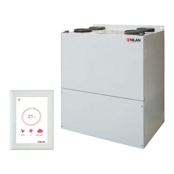
100 Pa. The size of the Comfort 200 Top makes it very useful in renovation projects in apartments and townhouses, where there is often a lack of space. The unit ventilates the dwelling by drawing out damp and vitiated air through valves placed in, for instance, bathroom, lavatory, kitchen and utility room. -
Page 6: Dimensional Drawing Comfort 200 Top
Dimensional drawing Comfort 200 Top Dimensional drawing Comfort 200 Top All listed measurements are in mm. Right model: Left model: Connections: 1. Outdoor air 2. Supply air 3. Extract air 4. Discharge air 5. Condensate drain... -
Page 7: Functional Block Diagram
Functional diagram Functional block diagram Connections 1: Outdoor air 2: Supply air 3: Extract air T1 /T8 4: Discharge air 5: Condensate drain 6: Electrical or water after-heating element connection Automation T2/T7: Supply air sensor T3: Extract air sensor T4: Discharge air- and deicing sensor T1/T8: Outdoor air sensor T9: Frost protection water after-heating element sensor... -
Page 8: Accessories
If you want to adjust the fan speed level in accordance with the level of use of the dwelling/building (amount of people), you can retrofi t a CO sensor. Nilan’s CO sensors calibrate automatically. On the control panel, you select the CO level you want. -
Page 9: Expansion Pcb
However, if you install a Nilan water trap with ball, the ball will ensure permanent function of the water trap. This saves you refi lling the water trap manually every autumn to ensure that it works. -
Page 10: Extension Cable Hmi Control Panel
You can control your ventilation unit with a smartphone app via a gateway connection. Connect the Nilan Gateway to a CTS400 or a CTS602 control system. This way, a cloud connection to the unit can be established. The Gateway is available in two different versions - with either a LAN or a WiFi... -
Page 11: Installation
Installation Placement Positioning of the ventilation unit Positioning of the ventilation unit ATTENTION When positioning the unit, you should always consider future service and maintenance. Therefore, we recommend that fl exible connections be fi tted between the ventilation unit and the duct system so that the unit can be easily removed. -
Page 12: Electrical Installation
Electrical installation Electrical connections Safety Safety ATTENTION All work must be carried out by qualifi ed persons and in compliance with existing legislation and regulations. ATTENTION It is important that the power is off, if you do work to the electrical components of the unit. It is important to check that wires are not damaged or squeezed during connection and use. -
Page 13: Ventilation Unit
Ventilation unit Ventilation unit Safety switch Power supply 230V ~ 50 HZ max. 13A... -
Page 14: User Panel
Nilan offers a connection cable with RJ12 plug of 15 m. It is also possible to customize a cable up to 50 m in length. A standard LAN cable is used for this. -
Page 15: Wall Bracket
Wall bracket Wall bracket Mount the HMI panel on the wall using the integrated wall bracket. The panel should be placed in a visible spot so it is possible to change settings and to monitor warnings or alarms regarding ope- ration of the unit. -
Page 16: Electrical Connections Accessories
Electrical connections accessories User selection 1 User selection 1 User selection 1 is connected via the 8-pin plug mounted on top of the unit. The user selection functions are used to override normal operation. The input signal must come from a potential-free switch. When closed, the function is activated with the settings selected in the control panel under Service / User selection. -
Page 17: User Selection 2
User selection 2 User selection 2 With User selection 2, the same options are achieved as with User selection 1. In addition, you get the option of a relay output that can control e.g. a damper or whatever need one may have to control an external function. User selection 2 potential-free input is connected to D3 and User selection 2 output is connected to relay RE2 on the CTS602 Light circuit board. -
Page 18: Fire Thermostat / External Fire Automation System
Fire thermostat / external fire automation system Fire thermostat / external fi re automation system The ventilation unit can be connected to an external fi re thermostat that will stop the ventilation unit in the event of fi re. The same port can be used for connection of an external fi re automation system. -
Page 19: Em Box (Damper Option)
EM Box (damper option) EM-Box (damper option) If you want to run the cooker hood via the ventilation unit, in some cases there may be insuffi cient air for cooker hood extraction. If you install an EM-box, you can regulate the extracted air when the cooker hood is in operation, so that less air is drawn from, for instance, the bathroom and the utility room. -
Page 20: Dtbu (Damper Option)
DTBU (damper option) DTBU (damper option) If you want to run the cooker hood via the ventilation unit, in some cases there may be insuffi cient air for cooker hood extraction. An EM-box solution can solve this. However, if there is insuffi cient space in the installation for an EM-box, the alternative may by to connect up a DTBU damper in the duct system. -
Page 21: External Pre-Heating Element
External pre-heating element External electrical pre-heating element It is possible to purchase an external electrical pre-heating element for frost protection of the ventilation unit. The electrical pre-heating element is mounted in the outdoor air duct before the unit with the necessary temperature sensor. If it is desired to see the actual outdoor air temperature on the control panel, the temperature sensor T1 / T8 must be led out into the duct before the pre-heating element. -
Page 22: Installation Of Expansion Pcb On Cts602 Light Circuit Board
5. Connect the wires up in accordance with the wiring diagram. ATTENTION The expansion PCB and the connections must be installed by a certifi ed electrician. The expansion PCB is an accessory for the CTS602 circuit board. Nilan does not supply external components. -
Page 23: Electrical After-Heating Element
Electrical after-heating element Electrical after-heating element An after-heating element is necessary if you want to control the supply air temperature. The electrical after-heating element can be purchased for installation in the supply air duct. The required sensor, Expansion PCB and connectors to the ventilation unit are included. ATTENTION The T7 temperature sensor is mounted after the heating element. -
Page 24: Water After-Heating Element
Water after-heating element Water after heating element An after-heating element is necessary if you want to control the supply air temperature. The water after-heating element can be purchased for installation in the supply air duct. The required sensors, Expansions PCB and connectors to the ventilation unit are included.. -
Page 25: Co 2 Sensor
sensor sensor If the extent to which a dwelling/building is used varies considerably, you will benefi t from installing a CO -sensor to control the air exchange. The CO -sensor measures the CO -level in the extract air. It then regulates the fan speed level accordingly. ATTENTION In order to be able to connect up a CO -sensor, the ventilation unit must have an expansion PCB. -
Page 26: Joint Alarm
Joint alarm Joint alarm It may be diffi cult to notice alarms if the unit is located in a place where access is diffi cult or infrequent, and if the control panel is located in the same place. An external alarm indicator in the form of an electric bulb or an acoustic signal can be connected to the ventilation unit and an- nounce when an alarm occurs. -
Page 27: Plumbing Installation
USEFUL INFORMATION As an accessory, Nilan can supply a water trap with ball. When the water trap dries out, the ball closes it off and ensures that air cannot be drawn into the ventilation unit. When condensate water is formed again, it will lift the ball, and the water will be able to drain away without problems. -
Page 28: Water After-Heating Element - Duct Installation
B3 Actuator and regulation valve Danfoss AME 140/24V 0-10V signal, 2-way valve VZ2 Kv 0.4 (Nilan supply), the Kvs value must be checked against the power supply. Differential pressure: 0.1 - 0.6 bar. With a fl ow temperature of 60 °C and at maximum Return fl... -
Page 29: Ventilation Installation
Nilan can supply Soundfl ex tubes that you can use as fl exible connections between the ventilation unit and the duct system. They will also reduce sounds from the system considerably. -
Page 30: Supply Air
Supply air Supply air Install supply air valves in living areas. Place them strategically so they cause minimum discomfort. It is, for instance, not recom- mended that you install supply air valves in areas where people are inactive, as the supply air may be experienced as draughty. Living areas may be, for example: •... -
Page 31: Balancing
Balancing Important information Imortant information ATTENTION To ensure the ventilation system operates optimally, it is important that it is balanced correctly. We recommend that experts do this. It is important to measure the total supply air and the total extract air. The system must have a minimum vacuum, which means it draw out more air than it blows in. - Page 32 25 St Leonards Road, Horsham RH13 6EH West Sussex Tel: +44 (0) 14 03 56 30 45 service@slservicesgroup.com info@slservicesgroup.com www.slservicesgroup.com Ireland: Nilan Ireland Ballylahive, Abbeydorney Tel: +353 (0) 87 97 98 361 maurice@nilan.ie www.nilanireland.ei Nilan A/S Nilanvej 2 8722 Hedensted Danmark Tlf.
Need help?
Do you have a question about the Comfort 200 Top and is the answer not in the manual?
Questions and answers