
Related Manuals for nilan Comfort 250L


Summary of Contents for nilan Comfort 250L
- Page 1 INSTALLATION INSTRUCTIONS CTS400 BY NILAN Comfort 250L/R-350L/R Comfort 250L/R-350L/R Polar Gateway Version 1.20 - 15.02.2024 M75 Comfort 250L/R-350L/R_GB...
-
Page 2: Table Of Contents
Table of contents General information Safety ............................................. 4 Power supply ........................................4 Introduction........................................... 4 Documentation........................................ 4 Unit type ..........................................5 Product description ......................................5 Dimensional drawing (L) ....................................6 Dimensional drawing Polar (L) ..................................6 Dimensional drawing (R) ....................................7 Dimensional drawing Polar (R) .................................. - Page 3 Electrical connection accessories ...................................16 Overview of connection options ................................16 LAN cable type A and B ....................................16 Overview of connection boxes ...................................17 User selection 1 and 2 (cooker hood) ................................18 Modbus ...........................................18 Joint alarm ........................................18 Fire thermostat / external fire automation system ..........................19 EM-box (damper option) ....................................19 DTBU (damper option) ....................................20 External electrical pre-heating element ..............................21...
-
Page 4: General Information
The instructions can be downloaded from www.nilan.dk. If you have questions regarding installation and operation of the unit after having read the instructions, please contact your nearest Nilan dealer. A list of Nilan dealers is available on www.nilan.dk. ATTENTION The unit must be started up immediately after installation and connection to the duct system. -
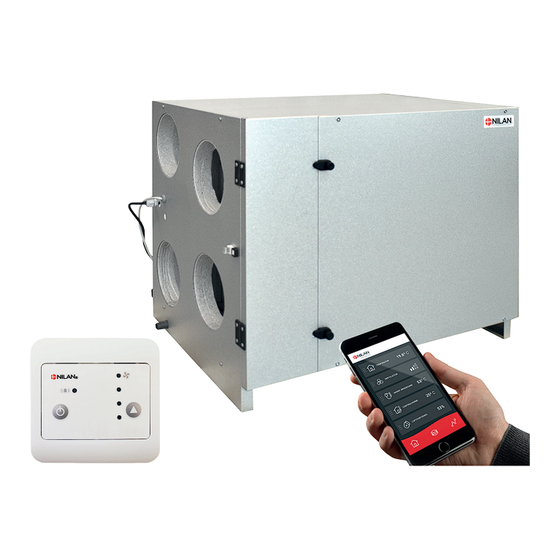
Page 5: Unit Type
250/372 m Comfort 250L/R / 350L/R is a compact unit that can be placed in the attic. The 4 nozzles of the unit are located on the same side, which provides some other options in relation to the installation. -
Page 6: Dimensional Drawing (L)
Dimensional drawing (L) Dimensional drawing (L) The illustration is of a left-facing version (L). Front Left side Connections: Outdoor air Supply air Extract air Discharge air Condensate drain NB! Spouts for inlet ring Bottom All listed measurements are in mm. Dimensional drawing Polar (L) Dimensional drawing Polar (L) The illustration is of a left-facing version (L). -
Page 7: Dimensional Drawing (R)
Dimensional drawing (R) Dimensional drawing (R) The illustration is of a right-facing version (R). Front Front Right side Højre side Connections: Outdoor air Supply air Extract air Discharge air Condensate drain NB! Spouts for inlet ring Bottom Bund All listed measurements are in mm. Dimensional drawing Polar (R) Dimensional drawing Polar (R) The illustration is of a right-facing version (R). -
Page 8: Functional Block Diagram
Functional block diagram Functional block diagram Connections 1: Outdoor air 2: Supply air 3: Extract air 4: Discharge air 5: Condensate drain 6: Electrical or water after-heating element connections T1 /T8 Automation T2/T7: Supply air sensor T3: Extract air sensor T4: Discharge air- and deicing sensor T1/T8: Outdoor air sensor T9: Frost protection water after-heating ele-... -
Page 9: Accessories
Accessories Electrical pre-heating element for frost protection of the unit Electrical pre-heating element for frost protection of the unit If your ventilation unit is not a Polar version with an integral pre-heating element, we recommend that you purchase an external pre-heating element as frost protection of the ventilation unit. During prolonged periods of frost, the high effi ciency counterfl... -
Page 10: Cts400 Connection Box
Fire connection box The Comfort ventilation unit has a function in its control system that can control 1-2 fi re dampers. If you want to activate this function, Nilan can supply you with a Fire Connection Box, with the following connection options: •... -
Page 11: Pollen Filter
Cooker hood fi lter box If the extract air needs extra fi ltration, Nilan can supply a Cooker hood fi lter box. This can provide extra protection of the ventilation unit if you connect a cooker hood that has not got good fi lters. -
Page 12: Set-Up
Set-up Mounting Positioning of the ventilation unit Positioning of the ventilation unit ATTENTION When positioning the unit, you should always consider future service and maintenance. Therefore, we recommend that fl exible connections be fi tted between the ventilation unit and the duct system so that the unit can be easily removed. -
Page 13: Surface Level
It is important that the unit is mounted on a surface level. Duct connections Duct connections An inlet ring needs to be fi tted (not supplied by Nilan). 1. Use size Ø160mm inlet ring. The Polar version is delivered 2. Press the inletrings fi rmly into the ventilation nozzles. -
Page 14: Electrical Installaton
Electrical installaton Electrical connections Safety Safety ATTENTION All work must be carried out by qualifi ed persons and in compliance with existing legislation and regulations. ATTENTION It is important that the power is off, if you do work to the electrical components of the unit. It is important to check that wires are not damaged or squeezed during connection and use. -
Page 15: Connecting A Gateway
Connecting to the internet Using an RJ45 cable, you connect the gateway to a router with internet connection (cable not supplied by Nilan). Once the gateway is connected to a power supply and connection to the router has been established, you will have a secure cloud connection. -
Page 16: Electrical Connection Accessories
LAN cable type A and B If you connect external accessories and you are using a LAN cable in stead of the CTS400 Connection Box from Nilan you must be aware if you use a type A or B LAN cable, as the wires are situated differently. -
Page 17: Overview Of Connection Boxes
Overview of connection boxes Overview of connection boxes You can connect up external connections via 4 connection boxes, depending on which settings you have selected in the Software. Normal setting A CTS400 Connection Box allows you to connect up the following functions: Brown User selection output 500 mm... -
Page 18: User Selection 1 And 2 (Cooker Hood)
User selection 1 and 2 (cooker hood) User selection 1 and 2 (cooker hood) If the fi re automation system has not been activated in the software, you will have access to both User selection 1 and User selection 2. ATTENTION If the fi re automation system has been activated, you will only have access to User selection 1. -
Page 19: Fire Thermostat / External Fire Automation System
Fire thermostat / external fire automation system Fire thermostat / external fi re automation system The ventilation unit can be connected up to an external fi re thermostat that will stop the ventilation unit in the event of fi re. The same port can be used for connection of an external fi re automation system. -
Page 20: Dtbu (Damper Option)
DTBU (damper option) DTBU (damper option) If you want to run the cooker hood via the ventilation unit, in some cases there may be insuffi cient air for cooker hood extraction. ATTENTION DTBU-spjæld løsningen kan ikke anvendes, hvis brandautomatikken er aktiveret i softwaren. An EM-box solution can solve this. -
Page 21: External Electrical Pre-Heating Element
External electrical pre-heating element External electrical pre-heating element It is possible to purchase an external electrical pre-heating element for frost protection of the ventilation unit. The electrical pre-heating element is mounted in the outdoor air duct before the unit with the necessary temperature sensor. If it is desired to see the actual outdoor air temperature on the control panel, the temperature sensor T1 / T8 must be led out into the duct before the pre-heating element. -
Page 22: Electrical After-Heating Element
Electrical after-heating element Electrical after-heating element If you want to control the supply air temperature, you will need an after-heating element. You can purchase an electrical after-heating element for installation in the supply air duct. It comes with the required sensor, Connection Box and connection to the ventilation unit. -
Page 23: Water After-Heating Element
Water after-heating element Water after-heating element If you want to control the supply air temperature, you will need an after-heating element. You can purchase a water after-heating element for installation in the supply air duct. It comes with the required sensor, connection box and connection to the ventilation unit. -
Page 24: Plumbing Installation
Plumbing installation Condensate drain Connection of water trap Connection of water trap It is important that the water trap complies with the measurements below. If the water trap is placed outside the climate screen, it should be protected against frost. Ø20 mm min. -
Page 25: Plumbing Connections Accessories
Supply fl ow Actuator and regulation valve Danfoss AME 140/24V 0-10V signal, 2-way valve VZ2 Kv 0.4 (Nilan supply), the Kvs value must be checked against the power supply. Differential pressure: 0.1 - 0.6 bar. With a fl ow temperature of 60 °C and at maximum heat output, the temperature is estimated to fall Return fl... -
Page 26: Fire Automation System
It is important to check that wires are not damaged or squeezed during connection and use. Usage Usage Nilan’s fi re automation system is used to monitor, test and check the fi re protection components of the ventilation system: • Fire and smoke damper, and fi re thermostat Important functions: •... -
Page 27: Electrical Connection Fire Automation System
Connection of fire damper Connection of fi re damper As an optional extra you can purchase Nilan’s Fire Connection Box for connection of fi re dampers. The fi re automation system is integrated into the control system. Belimo fi re damper... -
Page 28: Connecting Two Fire Dampers
EM-box/DTBU damper, Nilan can supply a Connection Box for connecting up the EM-box/DTBU damper. You can connect up the Connection Box to the Nilan Fire Connection Box (as illustrated). The fi re damper is also connected up here. -
Page 29: Alarm Code
Alarm code Alarm code Set an alarm 96 - “Damper test” if a position (open / closed) has not been fulfi lled within the maximum moving time of 120 seconds. The test will fail if: • Current starting position (open) is incorrect. •... -
Page 30: Schedule For Functional Testing
Schedule for functional testing Schedule for functional testing ATTENTION DS428 requires written documentation of the annual test of the Fire automatic system. Date: Comments: Tested by:... -
Page 31: Ventilation Installation
Nilan can supply Soundfl ex tubes that you can use as fl exible connections between the ventilation unit and the duct system. They will also reduce sounds from the system considerably. -
Page 32: Extract Air
Extract air Extract air Install the extract air valves in high-humidity rooms and place them strategically where they can extract humid and vitiated air from the dwelling/building most effi ciently. High-humidity rooms are, for example: • Bathroom • Lavatory • Kitchen •... -
Page 33: Balancing
Balancing Important information Important information ATTENTION To ensure the ventilation system operates optimally, it is important that it is balanced correctly. We recommend that experts do this. It is important to measure the total supply air and the total extract air. The system must have a minimum vacuum, which means it draw out more air than it blows in. - Page 36 25 St Leonards Road, Horsham RH13 6EH West Sussex Tel: +44 (0) 14 03 56 30 45 service@slservicesgroup.com info@slservicesgroup.com www.slservicesgroup.com Ireland: Nilan Ireland Ballylahive, Abbeydorney Tel: +353 (0) 87 97 98 361 maurice@nilan.ie www.nilanireland.ei Nilan A/S Nilanvej 2 8722 Hedensted Danmark Tlf.
Need help?
Do you have a question about the Comfort 250L and is the answer not in the manual?
Questions and answers