nilan CTS602 LIGHT Installation Instructions Manual
Hide thumbs
Also See for CTS602 LIGHT:
- User manual ,
- Installation instructions manual (48 pages) ,
- Manual (40 pages)

Related Manuals for nilan CTS602 LIGHT


Summary of Contents for nilan CTS602 LIGHT
- Page 1 INSTALLATION INSTRUCTIONS CTS602 LIGHT BY NILAN Comfort 200 Top (English) Version 3.01 - 16.01.2019...
-
Page 2: Table Of Contents
TABLE OF CONTENTS Safety Power supply ....................................................Disposal ..........................................................Ventilation unit ..................................................... General information Introduction ........................................................General information prior to installation ......................................Final inspection ......................................................Ventilation ......................................................Unit type ........................................................... Product description .................................................. Dimensional drawing left model ..........................................Dimensional drawing right model .......................................... - Page 3 Comfort 200 Top (English) BY NILAN Plumbing connections accessories ..........................................Water trap with ball (option) ............................................Water heating element for after-heating (accessory) - duct mounted ...................... Ventilation installation Duct system ......................................................Legislation ...................................................... Ducts ........................................................Unit .......................................................... Extract air ......................................................
-
Page 4: Power Supply
Always disconnect the power supply to the unit before opening the unit doors, for instance for installation, inspection, cleaning and filter change. Disposal Ventilation unit Nilan’s units consist mainly of recyclable materials. They must, therefore, not be mixed with household waste, but must be delivered to your local recycling center for disposal. -
Page 5: General Information Introduction
Instructions can be downloaded from Nilan’s website: http://www.nilan.dk/en-gb/frontpage/download If you have questions regarding installation of the unit after having read the instructions, contact your nearest supplier of Nilan products, who can be found on www.nilan.dk/en-gb/frontpage/download/ dealers. The purpose of these instructions is to advice the installer on correct installation and maintenance of the unit. -
Page 6: Unit Type
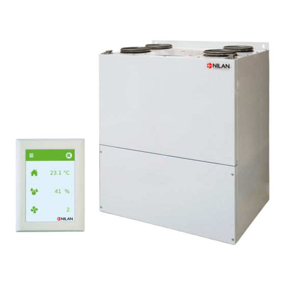
Unit type Product description Comfort 200 Top is a ventilation unit with heat recovery. The unit is intended for air volumes up to 308 m3/h /h at 100 Pa external duct pressure. The unit extracts humid and vitiated air from the dwelling via the bathroom, the lavatory, the kitchen and the utility room. -
Page 7: Dimensional Drawing Left Model
Comfort 200 Top (English) BY NILAN Dimensional drawing left model All dimensions are in mm. Connections: 1. Outdoor air 2. Supply air 3. Extract air 4. Discharge air 5. Condensate drain... -
Page 8: Dimensional Drawing Right Model
Dimensional drawing right model All dimensions are in mm. Connections: 1. Outdoor air 2. Supply air 3. Extract air 4. Discharge air 5. Condensate drain... -
Page 9: Functional Block Diagram
Comfort 200 Top (English) BY NILAN Functional block diagram Connections Automation 1. Outdoor air T2/T7: Supply air sensor 2. Supply air T9: After-heating element 3. Extract air T3: Extract air sensor 4. Discharge air T4: Discharge sensor and de-icing sensor 5. -
Page 10: Accessories
DTBU-damper If there is insufficient space in the installation to fit an EM-box, Nilan can provide a DTBU-damper that can be fitted between kitchen and bathroom. It has the same function as the EM-box, but you will have to run longer wires. -
Page 11: Pollen Filter
If the water trap dries out, air will be sucked into the unit and condensate water will not be able to drain. This will cause water damage. Nilan’s water trap contains a ball that ensures that no air is sucked into the unit and that condensate water can drain freely. -
Page 12: Set Up
Set up Installation Positioning of the unit ATTENTION When positioning the unit, you should always consider future services and maintenance. It must be easy to change filters, and it must, for instance, be possible to remove the heat exchanger, and to replace fans or other components. ATTENTION An open space of minimum 60 cm in front of the unit is recommended. -
Page 13: Mounting A Top Unit
Comfort 200 Top (English) BY NILAN Mounting a top unit The unit is equipped with mounting brackets with holes for wall mounting at the top back of the unit. Holes for wall mounting... -
Page 14: Electrical Installation Electrical Connections
Electrical installation Electrical connections Safety ATTENTION All work must be carried out by qualified persons and in compliance with existing legislation and regulations. ATTENTION It is important that the power is off, if you do work to the electrical components of the unit. It is important to check that wires are not damaged or squeezed during connection and use. -
Page 15: User-Panel Panel
Comfort 200 Top (English) BY NILAN User-panel panel HMI User panel The user panel is supplied with 1½ m cable. Connect the panel to the CTS602 control system in the unit using a CAT.5e cable (max. length 50 m). ATTENTION If you want a longer cable, use an ordinary LAN-cable, not a crossover cable, max. -
Page 16: Wall Bracket
Wall bracket Mount the HMI panel on the wall using the integrated wall bracket. The panel should be visible so it is possible to change settings and to monitor warnings or alarms regarding operation. The wall bracket is located at the back of Mount the bracket on the wall using 2 Click the RJ12 plug into place at the the panel. -
Page 17: User Panel Connection
Comfort 200 Top (English) BY NILAN User panel connection... -
Page 18: Electrical Connection Unit
Electrical connection unit Power supply CAUTION The power supply, including a safety switch, must be installed by an authorised electrician. A power cable for connection to a power socket is included. It is important that the unit is earthed. The unit is supplied with an EU plug for a 230V power supply. This means that, in principle, you have no protection of electrical grounding. -
Page 19: Electrical Connection Accessories
Comfort 200 Top (English) BY NILAN Electrical connection accessories Connection to user selection and Modbus User selection: Connection to user selection can be used, for instance, for controlling a cooker hood. This happens via a potential free contact in the cooker hood that sends a signal to the unit, which, in turn, increases ventilation when the cooker hood is on. -
Page 20: External Electrical Pre-Heating Element
External electrical pre-heating element If your unit is not the Polar version with an integrated pre-heating element, you can purchase and retrofit an external electrical pre-heating element. The electric preheating element is mounted in the outdoor air duct before the unit with the necessary temperature sensor. -
Page 21: Connecting Expansion Pcb
Comfort 200 Top (English) BY NILAN Connecting Expansion PCB If you connect an Expansion PCB to the CTS602 Light circuit board, you will be able to connect a CO sensor and an after-heating element. Expansion PCB 0-10V CTS602 circuit board Connect the Expansion PCB to the CN9 socket on the CTS602 circuit board. -
Page 22: Electrical After-Heating Element
0-10V 1x230V ~ 50 Hz max. 16A Min. 50 cm Min. 2xDia CTS602 Light 0-10V Expansion PCB Wiring diagrams are supplied with the products. Run the wires along the duct and through a grommet on the unit down to the PCB. Connect the wires in accordance with the wiring diagram. -
Page 23: Water After-Heating Element
Connecting the sensors Min. 50 cm Min. 2xDia CTS602 Light Expansion PCB T7: Temperature sensor - T9: Temperature sensor heating element - B3: Frost protection Run the wires along the duct and through a grommet down to the PCB. Connect them in accordance... - Page 24 Electrical connection of regulation valve 0-10V CTS602 Light Expansion PCB Run the wires along the duct and through a grommet on the unit down to the PCB. Connect the wires in accordance with the wiring diagram. Dimensional drawing: 3/4" RG...
-
Page 25: Plumbing Installation Condensate Drain
INFO Nilan offers a water trap with a ball. The ball ensures that no air blows into the unit through the condensate drain if the water trap dries out. This ensures that water in the condensate tray can... -
Page 26: Connection Bottom
Connection bottom Ø20 mm min. 50 mm Ø20 mm min. 170 mm min. 50 mm Connection of water trap generally Connecting Nilan’s water trap with ball... -
Page 27: Plumbing Connections Accessories
Comfort 200 Top (English) BY NILAN Plumbing connections accessories Water trap with ball (option) Connection options with Nilan’s water trap: 1. Water trap with Ø32 mm reducing fitting 2. Reducing fitting for Ø20 mm 3. Reducing fitting for ¾" RG 4. -
Page 28: Water Heating Element For After-Heating (Accessory) - Duct Mounted
Supply flow Return flow 1. Water heating element 2. Actuator and regulation valve: Danfoss AME 140/24V 0-10V signal, 2-way valve VZ2 Kv0.4 (Nilan supplies this) the Kvs value MUST be checked against the power supply. Differential pressure: 0.1-0.6 bar. With a supply flow temperature of 60°C and at maximum heat output the temperature is estimated to fall with 20°C through the heating element. - Page 29 Comfort 200 Top (English) BY NILAN IMPORTANT regarding Danfoss Actuator type AME 140: Reinstallation of the actuator MUST be done in the following manner: 1. Disconnect the power supply and remove the cover from the actuator. 2. Release the gear by pressing and holding the button at the bottom of the actuator, while turning the spindle fully (anticlockwise) 3.
-
Page 30: Ventilation Installation
Nilan offers flexible Sound Flex tubes that provide a flexible connection between the unit and the duct system, but also reduce the sound transmission from the unit to the duct system. -
Page 31: Extract Air
Comfort 200 Top (English) BY NILAN Extract air Install exhaust air valves in rooms that generate humidity. Place them strategically where they can extract humidity most effectively. Rooms that generate humidity: • Bathroom • Lavatory • Kitchen • Utility room Supply air Install supply air valves in living areas. -
Page 32: Installation Example
Installation example... -
Page 33: Balancing
Comfort 200 Top (English) BY NILAN Balancing Important information ATTENTION To ensure the ventilation system operates optimally, it is important that it is balanced correctly. We recommend that experts do this. It is important to measure the total supply air and the total extract air. The system must have a minimum vacuum, which means it must draw out more air than it blows in. - Page 35 Comfort 200 Top (English) BY NILAN...
- Page 36 United Kingdom: S L Services 25 St Leonards Road, Horsham RH13 6EH West Sussex Tlf. +44 (0) 7919 444452 stuart315@aol.com www.nilanuk.com Ireland: Nilan Ireland Ballylahive, Abbeydorney Tlf. +353 (0) 87 9798361 maurice@nilan.ie www.nilanireland.ie Nilan A/S Nilanvej 2 DK-8722 Hedensted Tlf.
Need help?
Do you have a question about the CTS602 LIGHT and is the answer not in the manual?
Questions and answers