nilan Compact P Installation Instructions Manual
Hide thumbs
Also See for Compact P:
- Installation instructions manual (56 pages) ,
- User manual (48 pages) ,
- Software instructions (36 pages)

Subscribe to Our Youtube Channel
Related Manuals for nilan Compact P


Summary of Contents for nilan Compact P
- Page 1 INSTALLATION INSTRUCTIONS CTS700 TOUCH BY NILAN Compact P / Compact P Polar - AIR9/AIR9+ Version 4.00 - 17.11.2020 M32_Compact-P-AIR9-AIR9+_GB...
-
Page 2: Table Of Contents
Placement of the Touch panel ................................. 25 Mounting the wall bracket ................................26 Electrical connections unit ..................................27 Power supply ...................................... 27 Compact P AIR ....................................27 Change from 400V to 230V ................................28 Circulation pump ....................................29 Electrical connections accessories ................................ 30 SHW hot water tank ................................... - Page 3 BAH Geothermal heater ..................................40 Active cooling function ..................................41 Plumbing installation Condensate drain ......................................42 Important information ..................................42 Hot water tank ......................................43 Connection overview ..................................43 Connection ......................................43 Requirements for water quality ..............................44 Hot water circulation ..................................44 Supplementary coil ....................................
-
Page 4: General Information
General information Safety Power supply CAUTION Always disconnect the power supply to the unit if an error occurs that cannot be rectified via the control panel. CAUTION If an error occurs on electrically conductive parts of the unit, alway contact an authorised electrician to rectify the error. CAUTION Always disconnect the power to supply to the unit before opening the unit doors, for instance for installation, inspection, cleaning and filter change. -
Page 5: Water Quality Requirements
Requirements for water quality The hot water tank in the Nilan units is made of steel, which has been given a double enamelling, to ensure an extra long service life. In addition, the tank is equipped with a sacrificial anode as extra protection. It is important that the sacrificial anode is replaced regularly. -
Page 6: Unit Type
The heat pump has a reversible cooling circuit, which means that the cooling circuit can be turned and it can cool the supply air in the summer. Compact P can cool the supply air by up to 10 ° C in relation to the outdoor air. Due to the low air exchange, usually 1/2 time per hour, it will not act as an air conditioning system. -
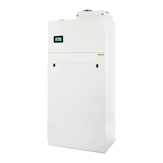
Page 7: The Installation's Internal Unit
The installation's internal unit Compact P: AIR: 1. Duct connections 21. 8 l expansion tank for central heating circuit 2. Front panel for filter changes 22. Safety valve and manometer for the central heating circuit 3. The control panel (touch-screen), can be moved out and 23. -
Page 8: The External Unit
The external unit * Photo: Example of AIR external/outdoor unit. The external/outdoor unit is available in several variants. 1. Evaporator element 2. Heat pump 3. Fan 4. Connectors to internal unit (liquid) 5. Condensate drain with integrated heating cable 6. Communication to internal unit and electrical connection... -
Page 9: Overview Of Temperature Sensors
Overview of temperature sensors Temperature sensors in the unit Temperature sensors outside the unit Temperature sensors in the hot water tank T1: Outdoor air T7: Supply air after heating element T11: Top of tank T2: Supply air (inlet) (accessory) T12: Bottom of tank T3: Extract air (outlet) T8: Outdoor air before preheating element T4: Extract air after heat exchanger... -
Page 10: Dimensional Drawing
Dimensional drawing Internal unit: Connections: 1. Outdoor air 2. Supply air 3. Extract air 4. Discharge air Internal unit weight: 257 kg AIR9 external unit weight: 125 kg AIR9+ external unit weight: 165 kg All listed measurements are in mm. - Page 11 AIR9 External unit: AIR9+ External unit:...
-
Page 12: Pipe Diagram
Pipe diagram Buffertank 3/4" supply flow 3/4" return flow 1" supply flow 1" return flow External AIR unit Internal AIR unit 18. Connection 1" 28. Manometer 19. Flexible hose 1" 29. Safety valve 2.5 bar 20. Shutoff valve 30. Shutoff valve with particle filter 21. -
Page 13: Accessories
Safety group By law, a safety group must be fitted for the cold water connection to the hot water tank. Nilan offers a safety valve in brass with the following functions: • Safety valve • Check valve •... -
Page 14: Vibration Absorbers
This should be placed in the outdoor air intake, which will reduce the pollen count in the dwelling. Trolley A Nilan trolley makes it easy to transport the heavy units into the home, without having to carry out heavy lifting yourself with the risk of injury. -
Page 15: Installation
Compact P is supplied in one piece on a pallet, packed in cardboard. You can use Nilan lifting trolley, with which the unit can be lifted directly off the pallet and into the building. If the filter box is removed, the unit can be manoeuvred through an ordinary door. -
Page 16: Installing The External Unit
Installing the external unit Installation transport of external unit The external AIR unit is supplied film-wrapped and fastened with straps to a transport pallet. If ground conditions allow, it is recommended that a lifting truck is used to move it. ATTENTION If the AIR unit is lifted in using a crane, please notice that the weight is not evenly distributed at the front and back. -
Page 17: Sound Data
Sound data The sound from the AIR unit's external unit can be propagated depending on where it is sited relative to the building and the underlying surface, as well as on other surrounding objects and surfaces. Q = 2 (free-standing) Q = 4 (against a wall) Q = 8 (in a corner) Sound effect LWA dB(A) 7/6 ºC - 30/35 ºC = 46 db(A) in accordance with EN14511, EN12102 and EN3743/1... -
Page 18: Installing The External Unit
Installing the external unit The external unit must always be installed on a firm, vertical and vibration-free surface and secured to some solid material if possible. Account must also be taken of the prevailing wind direction during the heating season, as the performance of the heat pump will be li- mited if the external unit is exposed to strong winds. -
Page 19: Fixing Of External Unit To Substrate
Fixing of external unit to substrate If the outdoor unit is placed in a place with a lot of wind, e.g. on a roof, it is necessary to attach it to the substrate using the 6 pre-drilled holes in the bottom. Pre-drilled holes ATTENTION The illustration above shows an example of an AIR outdoor unit. -
Page 20: Foundation
Foundation Adjustable feet Foundation Drain to condensate Soakaway Electrical conduit min. 50mm ATTENTION Place the AIR unit on a stable base, ideally a cast foundation. ATTENTION The illustration above shows an example of an AIR9 outdoor unit. See dimensional sketch for details on AIR9 and AIR9 +. -
Page 21: Condensate Drain
Condensate drain During operation, condensate will form in the external unit’s evaporator, and which has to be run off to a drain. From the evaporator condensation tray is mounted a 700mm hose which is led to the drain. The condensation drain must be insulated against frost, although a 1.5 m heating cable Ø25 / 4mm is included, which also helps to keep the condensation drain frost-free. -
Page 22: Dismantling The Front Doors Of The + Model
Dismantling the front doors of the + model If you need access to mechanics, electronics or plumbing connections in the AIR + outdoor unit, it is possible to remove the upper and lower front plate. WARNING Always disconnect the power to the unit before opening the doors at e.g. installation, inspection, cleaning and mainten- ance etc.. -
Page 23: Electrical Installation
1. Power supply 230V for Compact P 2. Grommets (a: Transmission cable between internal unit and Compact P, b: Sensor T18 to buffer tank, c: 3-way valve for SHW tank) 3. Crown sleeve for heat / cooling control (HEAT + COM: heat control. COM + COOL: cooling control) 4. -
Page 24: User Panel
User panel Touch Panel At delivery of the unit, the Touch panel is integrated in the front, but can be moved out, if you want to place it in e.g. the Kitchen or living room. The Touch panel should be located in a prominent place to allow changes to be made to the settings and for observing operational warnings or alarms. -
Page 25: Placement Of The Touch Panel
Placement of the Touch panel Below is shown how the touch panel can be moved out of the unit. The following page shows how to mount the wall bracket for the Touch panel. 1. Unscrew the two screws at the top of the lid so it can be 2. -
Page 26: Mounting The Wall Bracket
Mounting the wall bracket The Touch panel can be mounted on the wall using the integral wall-bracket. 1. The wall bracket is fixed to the wall with two screws. 2.a. Insert the RJ45 plug into the wall bracket with the top of the plug aligned with the dotted line in the wall bracket, and with the RJ45 release tab facing away from the wall. -
Page 27: Electrical Connections Unit
Due to the risk of faults caused by inductive influence, the communication cable must be routed in a separate pipe with a minimum of 100mm distance to other live cables. Power connection for Compact P, ventilation and hot water This power connection via Schuko socket allows to measure the power consumption of the ventilation separately, as well as the possibility that the hot water part does not have the same connection as the heat pump. -
Page 28: Change From 400V To 230V
Change from 400V to 230V The standard connection in the unit is 3x400V + N. In those countries or areas where this standard is not applicable, the unit can easily be switched to either 3x230V or 1x230V. The terminal block can be found in the control for AIR. Please refer to the wiring diagram enclosed with the unit. 3 x 400V + N 1. -
Page 29: Circulation Pump
Circulation pump In Compact P AIR and Compact P GEO, there is a Power supply cable for circulation pump for central circuit in the Electrical connection panel. The cable is marked with a sticker with the text "Circulation pump" and ends in 3 screw terminals. -
Page 30: Electrical Connections Accessories
Electrical connections accessories SHW hot water tank The SHW hot water tank is connected to Compact P AIR connection panel as shown below. The SHW tank has its own power supply via a Schuko connector. 1. RJ45 connector for transmitting top temperature (T21), bottom temperature (T22) and anode monitoring in the SHW tank. -
Page 31: User Selection 1
User selection 1 It is possible to override the unit's functions via an external signal from a potential free contact. The User selection function can be used for many purposes, e.g. in the case of a wood burning stove or open fire. Initial settings of the ventilation system should be set up with a slight underpressure, so that humidity in the air is not forced into the building elements. -
Page 32: External Pre-Heating Element
External pre-heating element It is possible to purchase an external electric pre-heating element for frost protection of the ventilation unit. The electric preheating element is mounted in the outdoor air duct before the unit with the necessary temperature sensor. If it is desired to see the actual outdoor air temperature on the control panel, the temperature sensor T1 / T8 must be led out into the duct before the preheating surface. -
Page 33: Co2 Sensor
sensor You can purchase a CO -sensor as an accessory if you want to control the fan speed level in accordance with the CO level in the dwel- ling. The T3 sensor is factory installed ( in the exhaust). The CO2 sensor in the unit: 1. - Page 34 7. Mount the power supply box in the box for automatic 8. Connects as shown in the electrical diagram below. (pre-drill 2 holes for the screws). 9. Reinstall the counterflow heat exchanger. Remember to reinstall the T4 sensor. Run the wire from the CO sensor to the circuit board and connect it as shown below: The three wires are connected as follows: GND: Blue...
-
Page 35: Smart Grid
Smart Grid If you wish to run Smart Grid, you will need to update to the latest Software version and connect the Smart Grid modem to Compact P, as shown. The Smart Grid signal is connected to the LC circuit board in the Compact P, which will also control AIR and GEO, if connected. Connect the signal directly, without resistance, as these are pre-installed in the cable. -
Page 36: Joint Alarm
Joint alarm If the unit is located in a place where access is poor or infrequent, and if the control panel is also located here, it may be hard to observe any alarms. An external alarm in the form of a light or acoustic signal, etc., can be connected to the unit. Cooker hood and EM box There are several benefits from connecting the cooker hood to the home’s ventilation system. -
Page 37: Fire Protection
Fire protection A fire thermostat or external fire automatic can be connected. It must be a joined signal, when it is broken the Compact P register it as a fire and stop the unit. Fire thermostat Note! If the unit is connected to external fire automatic, you set the software: General Settings/Service/Auto reset for external fire alarm to "On". -
Page 38: External Heat Supply
Compact P is able to control an external room heating such as electric radiators or a floor heating system. The room temperature is monitored by the Compact P, which block the external heating supply when there is no need for heating. If Compact P cannot achieve the desired room temperature through the ventilation, the external heating supply is released until the room temperature is in the desired level. -
Page 39: Connecting Ehd Damper
The EHD damper is connected via relay 7 and set on the display menu item: Ventilation / Frost protection or de-icing / Frost protection. (230V) ATTENTION Damper, geothermal pipe and roof vent are not supplied by Nilan. ATTENTION When using a geothermal pipe, the "Low ventilation a low outdoor temperature" feature cannot be used. -
Page 40: Bah Geothermal Heater
16. Bleed screw 12. Shut-off valves 17. Expansion tank 13. Particle filter 18. Pressostat 14. Filling and drain cocks 19. Circulation pump 15. Safety valve T8. Outdoor temperature sensor ATTENTION Circulation pump, heater and brine circuit are not supplied by Nilan. -
Page 41: Active Cooling Function
Active cooling function The AIR unit has a reversible cold circuit, which means that it can be used to actively cool the home, using either the floor heating sy- stem or fan coils. CAUTION If it is wished to operate with cooling, it is important to use glycol in the brine circuit to avoid icing in the heat pump. Active cooling using the floor heating There is an external temperature sensor connected to digital input 10. -
Page 42: Plumbing Installation
Condensate drain Important information Compact P is supplied with a reinforced 20 mm condensation drain pipe with built-in water lock. ATTENTION Run the condensate drain to the nearest drain, allowing an even fall of at least 1 cm per m. -
Page 43: Hot Water Tank
All work must be performed by qualified personnel and in accordance with relevant legislation and provisions. Nilan's hot water tanks are double-enamelled, ensuring long life. The efficient foam insulation protects against unnecessary heat loss. All connection nozzles for water have 3/4" thread and are located in the tank bottom. -
Page 44: Requirements For Water Quality
Requirements for water quality The hot water tank in the Nilan units is made of steel, which has been given a double enamelling, to ensure an extra long service life. In addition, the tank is equipped with a sacrificial anode as extra protection. It is important that the sacrificial anode is replaced regularly. -
Page 45: Central Heating
Central heating Water connection overview, internal unit 1. Feed to central heating, 3/4" 2. Return from central heating, 3/4" 3. Feed from external unit (hot), 1" 4. Return to external unit (cold), 1" 5. Circulation pump between external and internal units 6. -
Page 46: Connections List, External Unit
Connections list, external unit 1. Supply flow to internal unit (hot), fitted with 1" flexible hose 2. Return from internal unit (cold), fitted with 1" flexible hose 3. Condensate drain 4. Hole for connections ATTENTION The illustration above shows an example of an AIR outdoor unit. See dimensional sketch for details on AIR9 and AIR9 +. TRUE FALSE... -
Page 47: Insulation Of Hoses From The Outdoor Unit
Insulation of hoses from the outdoor unit It is important that the brine hoses between the indoor part and the outdoor part are well insulated, according to current standards. This is done to avoid heat loss and to achieve good operation. CAUTION If the brine hoses is not well insulated, the AIR heat pump will use significantly more energy and in worst case, there will not be enough heat in the house. -
Page 48: Plumbing Connections For Accessories
Plumbing connections for accessories Safety group CAUTION Safety group must be installed in connection with hot water tanks. When water is heated to 60 °C, it expands by 2%. A pressured tank could burst without a safety valve keeping excess water out. The safety valve should therefore drip during warming up. -
Page 49: Safety Group With Anti-Scald Protection
Safety group with anti-scald protection In the control, a temperature limit for the domestic hot water of 65ºC is set as standard. This setting prevents scalding of the users when the hot water tap is opened. When the unit is in cooling mode, the energy is deposited in the hot domestic water tank instead of leading it out of the house. This also means that if the hot water temperature exceeds 65ºC, the unit stops cooling the supply air. -
Page 50: Hot Water Tank
Hot water tank The AIR unit can be connected to an external hot water tank (SHW) or to the hot water tank in the Compact P (DHW). A three-way valve, which can be purchased as an accessory, is required. 3/4" supply flow Buffertank 3/4"... -
Page 51: Connecting To Shw Hot Water Tank
The domestic cold water is pre-heated in the SHW tank up to 45 °C by the AIR heat pump (factory setting 40 °C) through the heating pump coil (length 26 m). It is then fed to the DHW tank in the Compact P, where it is heated to the desired flow temperature. -
Page 52: Connection To Supplementary Coil In Shw Hot Water Tank
The SHW container is equipped as standard with a supplemental coil with a length of 8.5m. The supplementary coil can be connected to a solar panel with external solar heating control (not Nilan supply), or other heat source, which contributes to heating the domestic water. -
Page 53: Connecting To Dhw Hot Water Tank
Connecting to DHW hot water tank If the demand for domestic hot water is so great that the Compact P unit's heat pump cannot cope, the AIR unit can be connected to the DHW tank’s solar coil to help heat up the domestic hot water. -
Page 54: Ventilation Installation
This is to avoid vibrations from the unit being transmitted to the duct system. It will also make it easier to move the unit, which may be necessary during future services of the unit. Nilan can supply Soundflex tubes that you can use as flexible connections between the ventilation unit and the duct system. They will also reduce sounds from the system considerably. -
Page 55: Extract Air
Extract air Install the extract air valves in high-humidity rooms and place them strategically where they can extract humid and vitiated air from the dwelling/building most efficiently. High-humidity rooms are, for example: • Bathroom • Lavatory • Kitchen • Utility room Supply air Install supply air valves in living areas. -
Page 56: Balancing
Balancing Important information ATTENTION To ensure the ventilation system operates optimally, it is important that it is balanced correctly. We recommend that experts do this. It is important to measure the total supply air and the total extract air. The system must have a minimum vacuum, which means it draw out more air than it blows in. -
Page 57: Start-Up
Start-up Central heating Filling with water ATTENTION Before starting the heat pump and the circulation pump, the central heating circuit must be filled with water. Fill central heating circuit with water via the feed tap until the correct water pressure is obtained. It is important that all circuits in the central heating system are open during filling. -
Page 58: Troubleshooting
Emergency operation Emergency operation domestic hot water If an error occurs in the controller or components in the Compact P, and the unit therefore stops, it will not be able to produce domestic hot water. If the installer is not able to come right away or the error happens outside the opening hours, and you therefore cannot contact the in- staller, there is a possibility to get hot water by setting the unit into emergency mode. -
Page 59: Emergency Operation Central Heating
Emergency operation central heating If an error occurs in the controller or components in the AIR air/water heat pump, and the heat pump therefore stops, it will not be able to heat up the house by the central heating. If the installer is not able to come right away or the error happens outside the opening hours, and you therefore cannot contact the in- staller, there is a possibility to heat up the house by setting the heat pump into emergency mode. -
Page 60: Domestic Hot Water
Domestic hot water Errors and solutions domestic hot water Problem Possible cause Solution The unit produces insufficient domestic The filters may be blocked so that Change the filters and, if necessary, hot water. insufficient air is reaching the unit. change the filter change period to a shor- This can occur if the filters are not chan- ter Interval. -
Page 61: Central Heating
Central heating Problems and solutions central heating Problem Possible cause Solution The telestates call for heat, but the heat During the spring and autumn transition If you still want to heat in some rooms, pump does not start periods, some space telestates may call despite the average temperature of the for heat, but the heat pump does not house being warm enough, you can acti-... - Page 64 S L Services 25 St Leonards Road, Horsham RH13 6EH West Sussex Tel: +44 (0) 79 19 44 44 52 Service@nilanuk.com www.nilanuk.com Ireland: Nilan Ireland Ballylahive, Abbeydorney Tel: +353 (0) 87 97 98 361 maurice@nilan.ie www.nilanireland.ei Nilan A/S Nilanvej 2...
Need help?
Do you have a question about the Compact P and is the answer not in the manual?
Questions and answers