
Related Manuals for nilan Comfort 252 Polar


Summarization of Contents
Safety Precautions
Power Supply Safety
Guidelines for safely disconnecting power and handling electrical faults.
Disposal Instructions
Proper procedures for disposing of unit materials as recyclable waste.
General Information
Introduction and Documentation
Overview of supplied documents and where to find additional information.
Installation Guidelines
Information and warnings regarding unit startup and potential condensate issues.
Unit Settings Overview
List of settings for installer and user consultation, including ventilation levels and temperatures.
Unit Type and Description
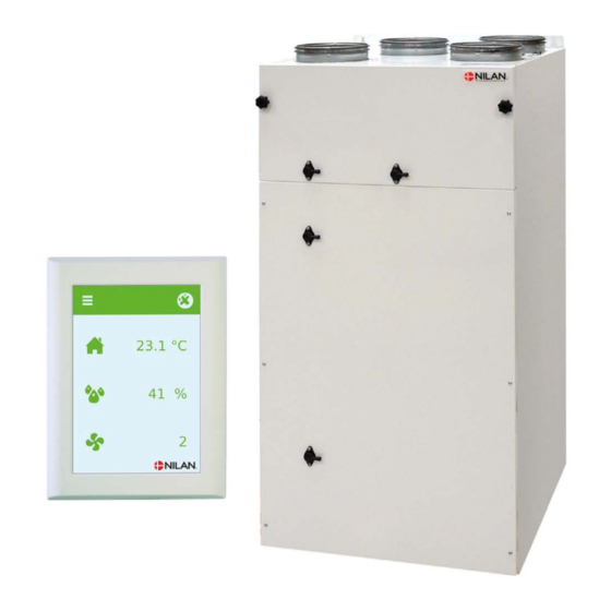
Product Overview
Description of the Comfort 252/302 Top ventilation unit with heat recovery and its airflow capacity.
Unit Dimensional Drawings
Right Version
Detailed measurements and connection points for the right version of the unit.
Unit Dimensional Drawings
Left Version
Detailed measurements and connection points for the left version of the unit.
Functional Diagram
System Overview
Diagram illustrating airflow paths, components, and automation sensors within the unit.
Unit Accessories
Pre-heating and Heating Elements
Elements for frost protection and increasing supply air temperature.
Airflow Control Accessories
EM box and DBTU damper for dividing extract air and controlling airflow.
Additional Accessories
Air Filtration and Quality
Pollen filter for air purification and CO2 sensor for ventilation control.
Condensate Management
Water trap for ensuring proper condensate drainage and preventing air intake.
Vibration and Noise Control
Vibration absorbers for dampening and flexible silencing for noise reduction.
Electrical Installation
Electrical Connections Overview
Safety precautions and list of connection points on the unit.
Control Panel Installation
HMI Control Panel Setup
Details on connecting the control panel using RJ12 and 8-pole plugs.
Wall Bracket Mounting
Panel Installation
Instructions for mounting the HMI panel on the wall using the bracket.
Connecting the Control Panel
Unit Integration
Visual guide showing the connection of the control panel to the ventilation unit.
Electrical Connection Unit
Power Supply Connection
Guidelines for connecting the unit to the 230V power supply and grounding.
Unit Power Requirements
Specifies power supply voltage, frequency, and maximum current for the unit.
Electrical Connection Accessories
User Selection and Modbus Communication
Connecting external signals for cooker hood operation and Modbus communication.
External Component Connections
Cable Routing
Instructions for routing external component cables through the unit's guide tube.
External Electrical Pre-heating Element
Installation and Safety
Details on mounting and connecting an external pre-heating element for frost protection.
Expansion PCB Installation
CO2 Sensor and After-heating Element Connection
Connecting an expansion PCB to the CTS602 Light for additional sensors and elements.
Electrical After-heating Element
Installation and Sensor Connection
Guide for installing an electrical after-heating element and connecting its temperature sensor.
Water After-heating Element
Sensor Integration
Instructions for connecting the water after-heating element and its associated temperature sensors.
Control Valve Electrical Connection
Wiring and Dimensions
Diagrams showing the electrical connection of the control valve and its dimensions.
Plumbing Installation
Condensate Drain Management
Important information and warnings regarding condensate drain setup and water traps.
Condensate Drain Connections
Water Trap Configuration
Diagrams illustrating water trap connections for both right and left versions.
Plumbing Accessories
Water Trap with Ball (Option)
Details and connection possibilities for the optional Nilan water trap with a ball.
Hot Water Heating Element
Duct Mounted Installation
Instructions for installing the hot water heating element accessory and its components.
Danfoss Actuator Procedure
Refitting Instructions
Mandatory steps for refitting the Danfoss Actuator type AME 140, including calibration.
Ventilation System Installation
Duct System Installation
Guidance on installing spiral tubes, NilAIR tubes, and flexible connections for duct systems.
Extract Air Configuration
Exhaust Valve Placement
Strategic placement of exhaust valves in moisture-generating rooms for effective air extraction.
Supply Air Configuration
Supply Air Valve Positioning
Strategic positioning of supply air valves in habitable rooms to ensure comfort and avoid drafts.
Roof Stack Installation
Inlet and Outlet Guidelines
Guidelines for positioning roof inlets/outlets to limit pressure fluctuations and prevent animal access.
Installation Example Diagram
System Visualization
Illustrative diagram showing a typical installation layout of the ventilation system within a house.
System Regulation
Initial Regulation Importance
Emphasis on correct initial regulation by experts for optimal system performance.
Balancing Connectors and Airflow Measurement
Using connectors to measure supply and extract air volumes via pressure drop.
Pressure Drop Diagram Interpretation
Explanation of how to use the pressure drop diagram to set main airflow for dry operation.
Need help?
Do you have a question about the Comfort 252 Polar and is the answer not in the manual?
Questions and answers