Table of Contents
Advertisement
Quick Links
Advertisement
Table of Contents

Subscribe to Our Youtube Channel
Related Manuals for ZKTeco MA500


Summary of Contents for ZKTeco MA500
- Page 1 MA500 Access Control Installation Guide & User Manual...
- Page 2 Important Note Document Privacy Note: Thank you for purchasing this product. Before using the unit, please read this manual carefully to avoid any unnecessary damage. The correct usage of this unit ensures fast and effect performance. No written consent will be given by our company, or individual representing our company to copy the content of this manual in part or in full, or distribute in any form what so ever.
-
Page 3: Table Of Contents
Table of contents Installation Guide 1. Equipment Installation ……………………………………………………………………………………………………………………………….…i 2. Structure and Function ……………………………………………………………………………………………………………………………...…ii 3. Lock Connection ……………………………………………………………………………………………………………………………………..…iii 4. Connected with Other Parts ………………………………………………………………………………………………………………… .….…iv 5. Connected with Power …………………………………………………………………………………………………………………………………v 6. Wiegand Output……………………………………………………………………………………………………………………………………..……vi 7. Communication ……………………………………………………………………………………………………………………………………….…vii User Manual 1. User Management ............................... 1 1.1 Administrator Operations ......................... -
Page 4: Equipment Installation
Access Control System Installation Guide 1. Equipment Installation Wall mount installation (1)Paste the mounting template (3)Take away the back plate. (4)Fix the back plate on (2)Remove the screws on On the wall. Drill the holes the solid wall according the bottom of device. According to the marks on the to the mounting paper. -
Page 5: Structure And Function
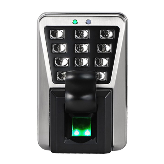
Access Control System Installation Guide 2. Structure and Function Access Control System Function: (1)If a registered user is verified, the device will trigger the lock control relay to open the door. (2)The door sensor will detect the on-off state. If the door is unexpectedly opened or improperly closed, the alarm relay will be triggered. - Page 6 Access Control System Installation Guide (I) Share power with the lock: +12V +12V Black Black DC 12V DC 12V White White Black Black NO LOCK Gray Gray NC LOCK FR107 Blue Blue FR107 Yellow Yellow Device share power with the lock: Orange Orange ULOCK=12V, I-ILOCK>1A……;...
-
Page 7: Connected With Other Parts
Access Control System Installation Guide 4. Connected with Other Parts 5. Connected with Power The device working voltage is DC 12V, electric current is 500mA (50mA for standby current). Positive is connected with ‘+12V’, negative is connect with ‘GND’. (Do not reverse the polarities). 6. -
Page 8: Communication
Equipment supports RS485 reader function, can be through the RS485 communication connected to FR1200 reader which is for slaver achieves RS485 Anti-passback function. If RS485 of MA500 is used for connecting with RS485 slave reader, then RS485 communication to PC is disabled. - Page 9 Access Control System Installation Guide Diagram of the device connect to controller as below: Set the 485 address (device number) by ZKAccess3.5 software. (2) TCP/IP Mode: (A)Cross-Over cable: the device connects (B)Straight-through: The device and PC to PC directly are connected to Switch.
-
Page 10: User Management
1. User Management Instructions Recommended Procedure: Step 1: Install the device and power on. Step 2: The administrator password is authenticated and changed. Step 3: Register users' fingerprints, cards, or passwords. Step 4: Configure access control parameters, including configuring the unlocking duration, authentication mode, stealth mode, door status sensor mode, and alarm. -
Page 11: Change Administrator Password
Access Control System User Manual Change Administrator Password 2. Press [8]. 1. Enter “* #” 3. Enter a new administrator (The indicator turns green and System password password. makes a beep.) “ #” Failed. (The indicator turns red and makes three beeps.) 4. -
Page 12: Batch Registration (Add Series Cards)
1. User Management 1. Enter “* #” 2. Press [1]. system password (The indicator turns green 3.Enter a user ID “#” and makes a long beep.) Failed. (The indicator turns red and makes three beeps.) 4. Register fingerprints or cards. 5. -
Page 13: Backup Registered User
Access Control System User Manual Note: 1. In the process of entering the user ID, 9 digits are verified automatically. For numbers with less than 9 digits, press # to enter the verification process. If the use ID exists, the indicator turns red and makes three beeps. -
Page 14: Delete Users
1. User Management 1. The device is in the 2. Press fingerprints, swipe cards, 3. The authentication is authentication state. or enter passwords. Press # after successful. entering a password. (The indicator turns green.) Failed. (The indicator turns red and makes two beeps.) Note: 1. -
Page 15: Delete All Users
Access Control System User Manual Delete All Users 1. Enter “* #” 2. Press[9]. 3.Press[9] system password (The indicator turns green (The indicator turns green “#” and makes a long beep.) and makes a long beep.) 5. Exit. 4. Deleting All Users is successful. (The device automatically exits the process (The indicator turns green and makes a when the operation is completed.) -
Page 16: Access Control Management
2. Access Control Management 2. Access Control Management 2.1 Configure Unlocking Duration 1. Enter “* #” 2. Press [4]. 3. Enter the unlocking system password (The indicator turns green duration.(Range: 1 to 10) “#” and makes a long beep.) 5.Exit. 4. -
Page 17: Configure Stealth Mode
Access Control System User Manual 2.3 Configure Stealth Mode If the Stealth mode is opened, the indicator light is off. 1. Enter “* #” 2. Press [0]. 3. Press [3]. system password (The indicator turns green (The indicator turns green “#”... -
Page 18: Configure Alarm
2. Access Control Management Note: 1. The door sensor mode configured here is used as the basis for the door sensor alarm. 2. In the process of configure door sensor mode setting, press 0 or 1 or 2 which is verified automatically, the indicator turns green and makes a long beep when the authentication is successful, the device automatically exits the process when the operation is completed, and the indicator turns red and makes a long beep. -
Page 19: Configure Tamper Alarm
Access Control System User Manual 1. Enter “* #” 2. Press[0]. 3. Press [2]. system password (The indicator turns green (The indicator turns green “#” and makes a long beep.) and makes a long beep.) 6. Exit. 5. The configuration is 4. -
Page 20: Configure Delay For The Door Status Sensor
2. Access Control Management Configure Delay for the Door Status Sensor DSen. Delay (Door Sensor Delay): indicates the delay in checking the door sensor after the door is open. If door sensor state is inconsistent with the normal state set by the door sensor switch, an alarm will be generated, and this period of time is regarded as the “door sensor delay”. -
Page 21: Faq
Access Control System User Manual Q: Does the MA500 support connect with external fingerprint reader? How to set the RS485 address of the external fingerprint reader? A: Yes, MA500 support connect with one external fingerprint reader via RS485 communication way. For the setting of its RS485 address, please refer to corresponding document of reader.
Need help?
Do you have a question about the MA500 and is the answer not in the manual?
Questions and answers