Sign In
Upload
Manuals
Brands
NKT Photonics Manuals
Measuring Instruments
Koheras ACOUSTIK
NKT Photonics Koheras ACOUSTIK System Manuals
Manuals and User Guides for NKT Photonics Koheras ACOUSTIK System. We have
1
NKT Photonics Koheras ACOUSTIK System manual available for free PDF download: Product Manual
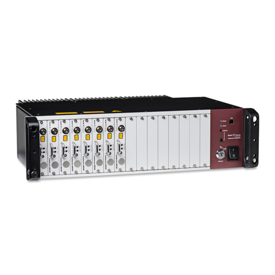
NKT Photonics Koheras ACOUSTIK Product Manual (96 pages)
Multi-Channel Modular Laser System
Brand:
NKT Photonics
| Category:
Measuring Instruments
| Size: 10.59 MB
Table of Contents
Guide Overview
3
BOOSTIK Amplifiers
3
Terminology
3
Table of Contents
5
Tables
9
Figures
11
Procedures
13
Koheras Acoustik Description
15
1 Description
17
Optical Output
17
Figure 1 ACOUSTIK Front Panel
17
Slot Configurations
18
Front and Rear Panels
18
Front Panel
18
Figure 2 Multiplexed Optical Output Port
18
Figure 3: ACOUSTIK Front Panel Layout - BASIK Modules Only
19
Figure 4 System with a Single BASIK and BOOSTIK Module Installed
19
Rear Panel
20
Modulation
22
Miscellaneous
22
Safety
22
Control
22
System and Laser Management
22
Status Leds
23
Table 1 Status Leds
23
System Labels
24
System Labeling Update
24
Figure 6 Top Panel Label Locations
24
Figure 7 Rear Panel Label Location
24
Table 2 System Labels
25
Installing an Acoustik System
27
2 Mechanical Installation
29
General
29
Operating Environment
29
Heat Dissipation
29
BOOSTIK Modules
29
Table 3 BOOSTIK Installation Recommendations
30
Figure 8 Rear Panel Heat Sink
30
Rack Mounting the System
31
Front and Rear Rack Mounting
31
Figure 9 ACOUSTIK Installed in a 19 Inch Rack
31
Rack-Mounted Cooling
32
Blank Covers
32
Figure 10 Cooling a Multiple System Installation
32
Figure 11 Blank Cover Installed
32
Placing the System on a Surface
33
Operating and Storage Environment
33
3 Connecting the ACOUSTIK
35
Connecting the Safety Interlock
35
Interlock Operation
35
Figure 12 Interlock Connected to a Door Switch - Laser on
35
Figure 13 Interlock Connected to a Door Switch - Laser SHUTDOWN
36
Connecting an Interlock Door Switch
37
LEMO Connector (Door Switch Circuit)
37
Bus Defeater
37
Figure 14 Pre-Wired LEMO Connector
37
Procedure 1 Connecting the Door Interlock Circuit
37
Connecting Power
38
Connecting Modulation Signals
38
Connecting the Trigger Input or Output
38
Figure 15 External Bus Defeater
38
Table 4 Power Specifications
38
Figure 16 Trigger Input Circuit
39
Figure 17 Trigger Output Circuit
39
Input Trigger
39
Output Trigger
39
Trigger Signal
39
Connecting BASIK Optical Output to a BOOSTIK Input
40
Checking Optical Connectors
40
Figure 18 ACOUSTIK - Single BASIK and BOOSTIK Modules
40
Operating the Acoustik System
41
4 Communicating with the ACOUSTIK
43
CONTROL Software
43
Installing the Software
43
Connecting the ACOUSTIK to a PC with CONTROL
43
Procedure 2 Connecting a PC to the ACOUSTIK Using a USB Cable
43
Ethernet Connection
45
Procedure 3 Connecting a PC to the ACOUSTIK Using Ethernet
45
5 Enabling Emission
47
Safety
47
Preparation
47
Enabling Emission from All Modules
48
Procedure 4 Enabling Emission from All Inserted Modules
48
Enabling Emission from an Individual BASIK Module
50
Procedure 5 Enabling Emission from an Individual BASIK Module
51
Enabling Emission from an Individual BOOSTIK Module
53
Procedure 6 Enabling Emission from an Individual BOOSTIK Module
54
6 Using CONTROL
57
CONTROL Overview
57
Figure 19 GUI Panel Navigation
57
Table 5 CONTROL Panels and Menu Items
57
Figure 20 Panel Dragged to a New Location in the Main Window
58
Figure 21 Panels Dragged Outside the Main Window
58
Procedure 7 Relocating Panels
58
Relocating Panels
58
Connecting to the ACOUSTIK
59
Figure 22 Panels Dragged Outside the Main Window
59
Figure 23 Welcome Screen and Connecting
59
ACOUSTIK Modules - CONTROL Interface
60
Figure 24 Selecting the Controller or a Module to Display in CONTROL
60
Navigation
59
Toggling Panels
59
Status Panel - ACOUSTIK System
61
Status Indicators
61
Figure 25 Status Panel
61
System Info
62
Measurements
62
WL Mod Button and Indicator
62
Emission Button
62
CONTROL Settings
63
Figure 26 ACOUSTIK CONTROL Settings
63
Figure 27: Wavelength Modulation - Source Selection
64
Wavelength Modulation
64
Figure 28 Wavelength Modulation - Source Selection
65
Figure 29: Wavelength Modulation - Module Source Selection
66
Figure 30: Wavelength Modulation - ACOUSTIK Source Selected
66
Figure 31 Internal Generator Waveform Selection (Modulation Type)
67
Amplitude Modulation
69
Figure 32 Turning on Wavelength Modulation
69
Figure 33 Amplitude Modulation Settings
69
Ethernet
70
Figure 34 Ethernet Setting
70
Clock
71
Figure 35 Watchdog Setting
71
Watchdog
71
View
72
CONTROL Menu Items
72
Figure 36 Clock Setting
72
Figure 37 View Setting
72
Application Log
73
Figure 38 Menu Items
73
Figure 39 Serial Monitor
73
Serial Monitor
73
Figure 40 Serial Monitor
74
Control Panel
75
Figure 41 Operating Mode Set to Power
75
Module Overview
75
Figure 42: Module Overview - All Fields Selected
76
Table 6 Module Overview Fields
76
Figure 43 Module Overview Field Selection
77
Toggling and Sorting the Overview Fields
77
Appendices
79
A Specifications
81
Table 7 Mechanical Dimensions
81
Table 8 Operating and Storage Environment
81
Table 9 Electrical
81
Table 10 Safety and Regulatory Compliances
81
Figure 44 Mechanical Dimensions
82
B Service and Support Information
83
Servicing the Laser
83
Figure 45 Warranty Seal
83
Support Contact Details
84
Support Website
84
Shipping Address
84
C Interface Pin Assignments
85
Modulation Input/Output
85
External Bus
85
Table 11 Modulation Connector Pin Assignment
85
Table 12 External Bus Pin Assignment
85
D CONTROL Installation
87
Installing CONTROL
87
Procedure 8 Installing CONTROL
87
E ACOUSTIK Slot Configuration Rules
93
Table 13 ACOUSTIK Slot Configurations
93
Advertisement
Advertisement
Related Products
NKT Photonics Koheras HARMONIK Series
NKT Photonics Koheras HARMONIK
NKT Photonics Koheras ADJUSTIK HP
NKT Photonics Koheras ADJUSTIK
NKT Photonics Koheras BOOSTIK
NKT Photonics Koheras BASIK
NKT Photonics Koheras BOOSTIK LC
NKT Photonics Koheras BOOSTIK HP
NKT Photonics ADJUSTIK
NKT Photonics ADJUSTIK HP
NKT Photonics Categories
Measuring Instruments
Water Filtration Systems
Amplifier
Control Unit
Industrial Electrical
More NKT Photonics Manuals
Login
Sign In
OR
Sign in with Facebook
Sign in with Google
Upload manual
Upload from disk
Upload from URL