
Related Manuals for Hillstone SG-6000


Summary of Contents for Hillstone SG-6000
- Page 1 Hillstone SG-6000 T-Series Hardware Reference Guide www.hillstonenet.net TW-HW-TS-EN-V2.0-Y15M03...
- Page 2 Hillstone SG-6000 T-Series Hardware Reference Guide Name and Concentration of Toxic or Hazardous Substances and Elements in Products Toxic or hazardous substances and elements Component Lead Mercury Cadmium Cr6+ PDBE Metal parts Χ (including fasteners) Printed circuit board Χ assemblies and...
-
Page 3: About This Manual
About This Manual Thanks for choosing the network security products from Hillstone Networks, Inc. This document is an installation manual for Hillstone SG-6000 T-Series device to help you install the Hillstone SG-6000 T-Series device properly. This manual includes the following chapters: ... -
Page 4: Table Of Contents
Hillstone SG-6000 T-Series Hardware Reference Guide Table of Contents Chapter 1 Introduction ....................1 Overview ........................ 1 Hardware Overview ....................1 Front Panel ......................2 Back Panel......................5 LED Indicators ....................6 Hardware Parameters ..................7 Interface Expansion Modules................8 Power Supply Modules .................. - Page 5 Hillstone SG-6000 T-Series Hardware Reference Guide Connecting the Ethernet/Optical Cable ..............28 Connecting the AC Power Cable ................30 Connecting the DC Power Cable ................31 Verification after Installation ................... 31 Chapter 4 Boot and Configuration ................32 Introduction ......................32 Establishing a Configuration Environment ..............
- Page 6 Hillstone SG-6000 T-Series Hardware Reference Guide List of Figures Figure 1: SG-6000-T5860/SG-6000-T5060 Front View ..........1 Figure 2: SG-6000-T3860 Front View ................. 2 Figure 3: SG-6000-T5860/SG-6000-T5060/SG-6000-T3860 Back Panel ......2 Figure 4: SG-6000-T5860 Front Panel ................ 2 Figure 5: SG-6000-T5060 Front Panel ................ 3 Figure 6: SG-6000-T3860 Front Panel ................
- Page 7 Hillstone SG-6000 T-Series Hardware Reference Guide List of Tables Table 1: SG-6000-T5860 Front Panel Description ............3 Table 2: SG-6000-T5060 Front Panel Description ............4 Table 3: SG-6000-T3860 Front Panel Description ............5 Table 4: SG-6000-T5860/SG-6000-T5060/SG-6000-T3860 Back Panel Description ..5 Table 5: LED Descriptions ..................
-
Page 8: Chapter 1 Introduction
Chapter 1 Introduction Overview The Hillstone SG-6000 T-Series product models, which is developed by Hillstone Networks, has the ability to perform the proactive inspection and analysis, foresee the network risks, and perform the effective actions against the network risks. With... -
Page 9: Front Panel
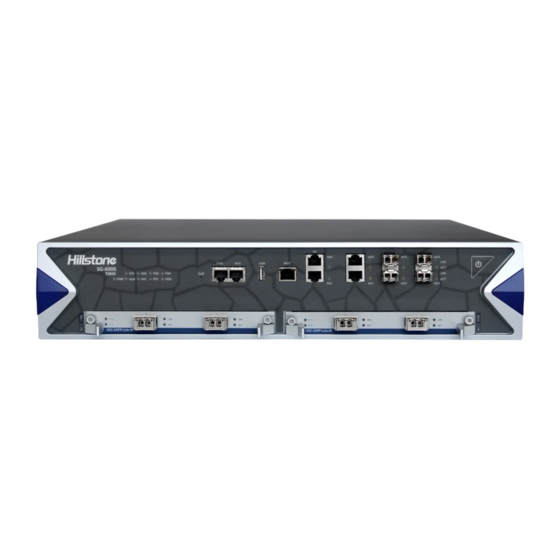
Figure 3: SG-6000-T5860/SG-6000-T5060/SG-6000-T3860 Back Panel Front Panel The front panel of SG-6000-T5860 consists of 1 power switch, 1 CLR button, 1 Console port, 1 Auxiliary port, 1 USB port, 1 MGT port, 2 HA ports, 2 Gigabit Ethernet ports, 4 SFP ports, 4 expansion slots, and LED indications. -
Page 10: Figure 5: Sg-6000-T5060 Front Panel
Gigabit Ethernet ports The front panel of SG-6000-T5060 consists of 1 power switch, 1 CLR button, 1 Console port, 1 Auxiliary port, 1 USB port, 1 MGT port, 2 HA ports, 2 Gigabit Ethernet ports, 4 SFP ports, 4 expansion slots, and LED indications. -
Page 11: Figure 6: Sg-6000-T3860 Front Panel
Gigabit Ethernet ports The front panel of SG-6000-T3860 consists of 1 power switch, 1 CLR button, 1 Console port, 1 Auxiliary port, 1 USB port, 1 MGT port, 2 HA ports, 2 Gigabit Ethernet ports, 4 SFP ports, 2 expansion slots, and LED indications. -
Page 12: Back Panel
Gigabit Ethernet ports Back Panel The back panels of SG-6000-T5860, SG-6000-T5060 and SG-6000-T3860 consists of 2 sets of power supply modules, 1 hard disk module, 1 fan tray, 1 anti-dust mesh, and 1 grounding screw. Figure 7: SG-6000-T5860/SG-6000-T5060/SG-6000-T3860 Back Panel... -
Page 13: Led Indicators
Hillstone SG-6000 T-Series Hardware Reference Guide LED Indicators The table blow describes the meanings of LED indicators on the front panels of Hillstone SG-6000 T-Series device: Table 5: LED Descriptions Color/Status Description The device power is running Green/Always on normally. -
Page 14: Hardware Parameters
Hillstone SG-6000 T-Series Hardware Reference Guide One of the fans on the fan tray has Orange/Always on failed. Change the fan tray as soon as possible. The cooling system has a serious error Red/Always on or the fan tray is not fully inserted. -
Page 15: Interface Expansion Modules
CPU. Flash Memory is used for storing the operating system firmware and application files. Interface Expansion Modules Hillstone SG-6000 T-Series device has expansion slots for the interface expansion. SG-6000-T5860 and SG-6000-T5060 support the following interface expansion modules: IOC-4GE-B-M, IOC-8GE-M, IOC-8SFP-M, IOC-2XFP-Lite-M, and IOC-4XFP. -
Page 16: Figure 10: Front Panel Of Ioc-8Ge-M
Hillstone SG-6000 T-Series Hardware Reference Guide Figure 10: Front Panel of IOC-8GE-M Figure 11: Front Panel of IOC-4GE-B-M Figure 12: Front Panel of IOC-4XFP Figure 13: Front Panel of IOC-4SFP+ The following table describes the meanings of LED indicators on the front panels of expansion modules. -
Page 17: Power Supply Modules
No data is transmitted on this port. Power Supply Modules Hillstone SG-6000 T-Series device uses the 1+1 mode for power supply. One power supply module is worked as the main one, and the other power supply is worked as the standby power supply. When the main power supply module interrupted, the standby power supply will be enabled instantly. -
Page 18: Figure 15: Dc Power Supply Module
Hillstone SG-6000 T-Series Hardware Reference Guide Figure 15: DC Power Supply Module The power supply module LED descriptions for Hillstone SG-6000 T-Series device are listed in the following table: Table 9: Power Supply Module LED Descriptions Color/Status Description Green/Always on Power module is functioning normally. -
Page 19: Hard Disk Modules
RS-232C Baud Rate 115200 bit/s Services Connect the external Bypass module of Silicom. USB Port Hillstone SG-6000 T-Series device provides an USB host port. Attributes for the USB host port are shown in the table below: Chapter 1 Introduction Hillstone... -
Page 20: Table 12: Usb Host Port Attributes
Caution: To avoid dust falling into the SFP socket, you should place a rubber dust cap (originally in the accessory box) over the SFP port. The SFP port of Hillstone SG-6000 T-Series device supports the SFP optical module. When connecting the SFP port to an Ethernet cable, use the SFP transceiver. -
Page 21: Table 14: Sfp Optical Module Attributes
1000Mbps SFP copper module Full-duplex If you choose to use SFP+ optical module in SFP+ port, you should use LC-Type optical connector. Hillstone device supports three types of SFP+ optical modules. All optical modules are hot-swappable. Chapter 1 Introduction Hillstone... -
Page 22: Table 16: Sfp+ Optical Module Attributes
Connector Ethernet_II Frame Format Ethernet_SNAP Negotiation Mode XFP optical module 10Gbps Hillstone SG-6000 T-Series device supports five types of 10GBase-FX XFP optical module. The optical module provides the LC connector. All optical modules are hot- swappable. Chapter 1 Introduction Hillstone... -
Page 23: Power Switch
(originally in the accessory box) over the XFP port. Power Switch There is a power switch at the front panel of Hillstone SG-6000 T-Series device. After supplying the device with electricity, the device powers up automatically. To power off the device, take the following steps: Use the save command to save the current configurations. -
Page 24: Expansion Slot
Hillstone suggest purchasing an auxiliary anti- dust mesh for the situation that the original anti-dust mesh is sent to Hillstone for clearing. Besides, it is recommended that you should replace the anti-dust mesh every 3 or 6 months according to the clearness status of your equipment room. -
Page 25: Figure 16: Fan Tray
Hillstone SG-6000 T-Series Hardware Reference Guide Figure 16: Fan Tray The air intake vent of the cooling system is located on the left side of the front panel. After the air passes through the device, it discharges from the exhaust vent on the right side of the back panel. -
Page 26: Chapter 2 Installation Preparations
Package disassembly Installation Site Environment Requirements Hillstone SG-6000 T-Series device is designed for indoor use. To ensure the normal operation and to prolong the service lifetime, the installation site must meet the requirements below. Temperature/Humidity Requirements The installation site must keep the appropriate temperature and humidity in the installation site. -
Page 27: Esd Prevention
Use electromagnetic shielding when necessary. Cabinet Requirements Hillstone SG-6000 T-Series device is designed to fit in standard 19-inch cabinet. The device can be installed in a 19-inch (or larger) cabinet. Cabinet Size and Clearance Install the device in at least 19-inch standard cabinet. Larger cabinet and adequate space can ensure better ventilation and heat dissipation. -
Page 28: Rack Requirements
Ensure the path of the cables used by the device will not affect the heat dissipation as far as possible. Rack Requirements Hillstone SG-6000 T-Series device can be installed in 19-inch four-post racks. Rack Size and Strength The rack rails must be spaced widely enough to accommodate the device chassis's external dimensions: 440.0 mm high, 515.0 mm deep and 88.4 mm wide. -
Page 29: Chapter 3 Installation
Hillstone SG-6000 T-Series Hardware Reference Guide Chapter 3 Installation Installation Processes Before installation, prepare the site according to the requirements in Chapter 2 Installation Preparations, and use the procedures below to install the device. 1. Perform security check according to Safety Requirements. -
Page 30: Preventing Esd Damage
When returning the hardware components to Hillstone, package the components in anti-static bags first. Fire Safety Requirement The installation site should conform to common fire safety regulations and have fire extinguishers in the room. -
Page 31: Installing Interface Expansion Modules
Hillstone SG-6000 T-Series Hardware Reference Guide Figure 18: Installing Rack-mounting Ears 5. Use the screws to attach the left and right brackets to the rack. Verify the alignment of the screws. Make sure every two screw pairs are in the same horizontal line. -
Page 32: Installing A Hard Disk Module
Hillstone SG-6000 T-Series Hardware Reference Guide Take the following steps to install the interface expansion modules 1. Make sure the device is not powered and you have worn antistatic gloves. 2. Face the front panel of the device. 3. Use a screwdriver to remove the blank panel from the expansion slot you want to insert. -
Page 33: Installing A Power Supply Module
Hillstone SG-6000 T-Series Hardware Reference Guide Use a screwdriver to re-install the blank panel into the hard disk slot. Figure 22: Installing the Blank Panel Installing a Power Supply Module This part describes how to install and remove the power supply module. The methods of installing AC power supply module and DC power supply module are the same, but the cable installation methods are different. -
Page 34: Connecting Cables
To avoid electrostatic discharge, you must correctly connect the chassis to the earth ground by a grounding wire. The grounding screws are in the back panel of the chassis, as shown in the figure below. Note that Hillstone does not provide grounding wire. -
Page 35: Connecting The Console Cable
Hillstone SG-6000 T-Series Hardware Reference Guide Connecting the Console Cable The device provides an RS-232C asynchronous serial console (CON) port, through which you can configure the appliance. The console cable is an 8-core shielded cable, which has an RJ-45 connector that can be connected to the Console port of the appliance and a DB-9 (female) connector that can be connected to the serial port of a console terminal. -
Page 36: Figure 25: Connecting The Ethernet Copper Cable
Hillstone SG-6000 T-Series Hardware Reference Guide Figure 25: Connecting the Ethernet Copper Cable Connecting the Ethernet Fiber Cable Follow the guidelines below when connecting cables to the ports: Be careful not to connect the Ethernet port to the wrong ports. Read the label above the port carefully. -
Page 37: Connecting The Ac Power Cable
Hillstone SG-6000 T-Series Hardware Reference Guide Figure 26: Connecting the Ethernet Copper Cable Warning: Laser danger! To protect your eyes from radiation harm, do not stare into a cable connector connected to a laser. Connecting the AC Power Cable The AC power cable is shipped with the chassis. Prepare a single-phase three- terminal power socket with a ground contact in advance. -
Page 38: Connecting The Dc Power Cable
Connecting the DC Power Cable To power the appliance with DC power source, use DC power cables to connect the appliance and the external DC power source. Hillstone does not provide DC power cables. Warning: Before performing the procedure, ensure that the cable is not connected with any power source and make sure the cables will not be powered on during the process. -
Page 39: Chapter 4 Boot And Configuration
Chapter 4 Boot and Configuration Introduction This chapter describes how to perform initial system boot and basic configuration of Hillstone SG-6000 T-Series device. The configuration uses PC as the console terminal. Establishing a Configuration Environment Hillstone SG-6000 T-Series device supports both local and remote configuration. -
Page 40: Webui
2. Launch a Web browser of the management PC, enter the URL http://192.168.1.1 in the address bar, and then press Enter. 3. Enter the default administrator name and password “hillstone” in both the Login and Password text boxes. Chapter 4 Boot and Configuration... -
Page 41: Telnet And Ssh
Hillstone SG-6000 T-Series Hardware Reference Guide 4. Click the Login button to enter WebUI main page. Then you can set other configurations to the appliance. Telnet and SSH You can also establish Telnet and SSH configuration environments. Basic Configuration Before beginning to use the device, you should be familiar with its features and your network deployment. -
Page 42: Chapter 5 Hardware Maintenance And Replacement
Hillstone SG-6000 T-Series Hardware Reference Guide Chapter 5 Hardware Maintenance and Replacement Introduction This chapter provides information on how to maintain and replace power module, expansion module and fan tray. General Maintenance For optimum performance, use the following routine maintenance procedures: Inspect the installation site for moisture, temperature and cleanness ... -
Page 43: Replacing A Dc Power Supply Module
Hillstone SG-6000 T-Series Hardware Reference Guide 6. Install a replacement power module (see Installing a Power Supply Module Connecting the AC Power Cable). Note: If you do not want to install a new module, apply a blank plate over the slot to avoid dust falling into the chassis. -
Page 44: Replacing A Hard Disk Module
Hillstone SG-6000 T-Series Hardware Reference Guide Figure 30: Replacing an Expansion Module 5. Put the removed module into an antistatic bag with component-side up. To install a new interface expansion module, view Installing Interface Expansion Modules. Note: If you do not want to install a new module, apply a blank plate over the slot to avoid dust falling into the chassis. -
Page 45: Replacing A Fan Tray
When one fan is failed, you need to change the fan tray for device heat dissipation. Hillstone suggest purchasing an auxiliary fan tray. When you change the original fan tray, use the auxiliary one for heat dissipation. The fan tray is hot-swappable. - Page 46 Hillstone SG-6000 T-Series Hardware Reference Guide 2. Hold the screws and pull the anti-dust mesh straight out of the chassis. Take the following steps to install the anti-dust mesh: Hold the screws and slide the anti-dust mesh into the slot until you feel resistant.
-
Page 47: Chapter 6 Troubleshooting
Hillstone SG-6000 T-Series Hardware Reference Guide Chapter 6 Troubleshooting Introduction This chapter provides solutions to some common problems of Hillstone SG-6000 T- Series device. Losing the Administrator Password If you lose the administrator password, please contact your local sales representative or you can reset the system to restore its factory password. -
Page 48: Troubleshooting The Configuration System
Hillstone SG-6000 T-Series Hardware Reference Guide Ensure that the voltage of the power source conforms to the required voltage. For the PWR LED information, see Indicators. Troubleshooting the Configuration System The Console configuration terminal shows system booting message when the appliance is powered on.
Need help?
Do you have a question about the SG-6000 and is the answer not in the manual?
Questions and answers