
Subscribe to Our Youtube Channel
Related Manuals for Hillstone SG-6000-E6360


Summary of Contents for Hillstone SG-6000-E6360
- Page 1 Hillstone StoneOS User Manual Hillstone Hardware Reference Guide www.hillstonenet.com...
- Page 2 Hillstone SG-6000 E-Series Hardware Reference Guide Name and Concentration of Toxic or Hazardous Substances and Elements in Products Toxic or hazardous substances and elements Component Lead Mercury Cadmium Cr6+ PDBE Metal parts Χ (including fasteners) Printed circuit board Χ assemblies and...
-
Page 3: About This Guide
Preface About This Guide Thanks for choosing the network security products from Hillstone Networks, Inc. This document is an installation guide for Hillstone devices to help you install the Hillstone device properly. This guide includes the following chapters: ♦ Chapter 1. Introduction ♦... -
Page 4: Table Of Contents
Hillstone SG-6000 E-Series Hardware Reference Guide Table of Contents CHAPTER 1 INTRODUCTION ............................1 ..................................1 VERVIEW ................................. 1 ARDWARE VERVIEW Front Panel .................................. 1 Back Panel ................................... 8 LED Indicators ................................11 System Parameters ..............................13 Ports ..................................17 CLR Button ................................ - Page 5 Hillstone SG-6000 E-Series Hardware Reference Guide Tenet and SSH ................................42 ............................... 42 ASIC ONFIGURATION CHAPTER 5 HARDWARE MAINTENANCE AND REPLACEMENT ..................43 ................................. 43 NTRODUCTION ......................43 NSTALLING AND EMOVING THE OWER UPPLY ODULE ......................44 NSTALLING AND EMOVING THE...
- Page 6 Figure 1-10: Front Panel of SG-6000-E1100 (WLAN version) ......... 7 Figure 1-11: Front Panel of SG-6000-E1100 (WLAN+3G version) ........8 Figure 1-12: SG-6000-E6360/E6160 Back Panel ............8 Figure 1-13: SG-6000-E5960/E5760/E5660 Back Panel ..........9 Figure 1-14: SG-6000-E5560/E5260/E3965 Back Panel ..........9 Figure 1-15: Back Panel of SG-6000- E3960/E3662/E3660/E2860/E2800/E2300/E1700/E1606 ........
- Page 7 Hillstone SG-6000 E-Series Hardware Reference Guide List of Tables Table 1-1: SG-6000-E6360 Front Panel Description ....................2 Table 1-2: SG-6000-E6160 Front Panel Description ....................2 Table 1-3: SG-6000-E5960/E5760/E5660 Front Panel Description ................3 Table 1-4: SG-6000-E5560/E5260/E3965 Front Panel Description ................4 Table 1-5: SG-6000-E3960 Front Panel Description ....................
-
Page 8: Chapter 1 Introduction
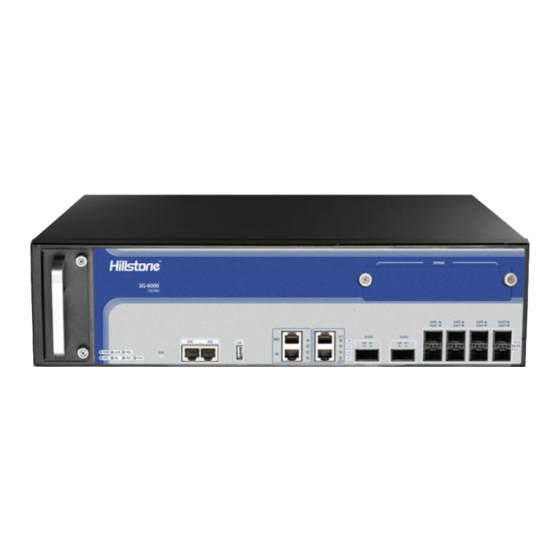
Front Panel The front panel of SG-6000-E6360 consists of 2 Gigabit Ethernet ports, 8 SFP+ ports, 2 QSFP+ports, 1 USB port, 1 HA port, 1 Management port, 1 Console port, 1 Auxiliary port, 1 CLR button, 1 Bypass expansion slot and several LED indicators. -
Page 9: Figure 1-2: Sg-6000-E6160 Front Panel
Hillstone SG-6000 E-Series Hardware Reference Guide Table 1-1: SG-6000-E6360 Front Panel Description Label Label Label PWR: Power LED FAN: Fan LED HA: HA port e0/0 - e0/1: Gigabit STA: Status LED CLR: CLR button Ethernet ports XLe0/2-XLe0/3: QSFP+ ALM: Alarm LED... -
Page 10: Figure 1-3:Sg-6000-E5960/E5760/E5660 Front Panel
Hillstone SG-6000 E-Series Hardware Reference Guide expansion slots and several LED indicators. The standard power supply for SG- 6000-E5960/E5760 is dual power supplies, and the product with single power supply is also available. Figure 1-3:SG-6000-E5960/E5760/E5660 Front Panel Table 1-3: SG-6000-E5960/E5760/E5660 Front Panel Description... -
Page 11: Figure 1-5: Front Panel Of Sg-6000-E3960
Hillstone SG-6000 E-Series Hardware Reference Guide Table 1-4: SG-6000-E5560/E5260/E3965 Front Panel Description Label Label Label e0/ - e0/3: Gigabit PWR: Power Ethernet ports (e0/2 and CLR: CLR button e0/3 support the Bypass function) STA: Status CON: Console port e0/4 - e0/7: SFP ports... -
Page 12: Figure 1-6: Front Panel Of Sg-6000-E3662/E3660/E2860
Hillstone SG-6000 E-Series Hardware Reference Guide Table 1-5: SG-6000-E3960 Front Panel Description Label Label Label e0/0 - e0/5: Gigabit PWR: Power CON: Console Ethernet ports (e0/0 and port e0/1 supports the Bypass function) STA: Status AUX: Auxiliary e0/6 - e0/9: SFP ports... -
Page 13: Figure 1-7: Front Panel Of Sg-6000-E2800 And Sg-6000-E2300
Hillstone SG-6000 E-Series Hardware Reference Guide SG-6000-E2800 and SG-6000-E2300 have the same front panel. The front panel consists of 5 Gigabit Ethernet ports, 4 Combo ports (Ethernet port + SFP port), 1 USB port, 1 Console port, 1 CLR button and some LED indicators. -
Page 14: Figure 1-9: Sg-6000-E1600 Front Panel
Hillstone SG-6000 E-Series Hardware Reference Guide The front panel of SG-6000-E1600 consists of some LED indicators. Figure 1-9: SG-6000-E1600 Front Panel Table 1-9: SG-6000-E1600 Front Panel Description Label Label Label PWR: Power LED STA: Status LED e0/0 - e0/8: Gigabit Ethernet... -
Page 15: Back Panel
WLAN: WLAN port status LED Back Panel SG-6000-E6360 and SG-6000-E6160 have the same back panel layout. The back panel layout of SG-6000-E6360/E6160 consists of 2 power supply sockets, 2 expansion slots, 1 grounding screw and 1 anti-dust mesh. Figure 1-12: SG-6000-E6360/E6160 Back Panel SG-6000-E5960 ,SG-6000-E5760 and SG-6000-E5660 have the same back panel layout. -
Page 16: Figure 1-13: Sg-6000-E5960/E5760/E5660 Back Panel
Hillstone SG-6000 E-Series Hardware Reference Guide Figure 1-13: SG-6000-E5960/E5760/E5660 Back Panel SG-6000-E5560 SG-6000-E5260 and SG-6000-E3965 have the same back panel The back panel consists of 2 power supply sockets, 1 grounding screw and 1 anti- dust mesh. The standard product of SG-6000-E5560/E5260/E3965 adopts dual power supplies and it is also available in single power supply. -
Page 17: Figure 1-17: Sg-6000-E1100 (Wlan Version) Back Panel
Hillstone SG-6000 E-Series Hardware Reference Guide Table 1-12: Back Panel Description of SG-6000-E1600 Label Label Label DC POWER: DC e0/0 - e0/8: Gigabit CON: Console port power interface Ethernet port CLR: CLR USB: USB port Security keyhole button SG-6000-E1100 (WLAN version) uses the power adapter. The back panel of SG-... -
Page 18: Led Indicators
Hillstone SG-6000 E-Series Hardware Reference Guide SG-6000-E1100 (WLAN+3G version) uses the power adapter. The back panel of SG-6000-E1100 (WLAN+3G version) has 1 power supply socket, 1 Console port, 1 CLR button, 9 Gigabyte Ethernet ports, 1 USB port, 1 grounding screw, 1 security keyhole, 2 SMA connectors for 3G antennas, and 2 SMA connectors for WLAN antennas. - Page 19 Hillstone SG-6000 E-Series Hardware Reference Guide Green/Blinking The system is running normally. Red/Always on The system has failed to boot or has an error. Red/Always on The system is sending alarm(s). Green/Blinking The system is waiting. Orange/Blinking The system is using a trial license.
-
Page 20: System Parameters
♦ As the number and type of LED indicators may vary from different product models, please refer to the actual product. System Parameters The following table lists the system parameters of Hillstone devices of all models. Table 1-16: System Parameters Item... - Page 21 Hillstone SG-6000 E-Series Hardware Reference Guide 2 Gigabit Ethernet ports 8 SFP+ ports 1 USB 2.0 Host port 1 MGT port SG-6000-E6160 1 HA port 1 Console port 1 Auxiliary port 4 Gigabit Ethernet ports 4 SFP ports 1 USB 2.0 Host port...
- Page 22 Hillstone SG-6000 E-Series Hardware Reference Guide SG-6000-E2300 4 Gigabit Combo ports (Ethernet port + SFP port) 1 USB 2.0 Host port 1 Console port SG-6000-E1700 SG-6000-E1606 9 Gigabit Ethernet ports SG-6000-E1600 1 USB 2.0 Host port SG-6000-E1100 (WLAN version) 1 Console port...
- Page 23 Hillstone SG-6000 E-Series Hardware Reference Guide (W×D×H) SG-6000-E6160 110.0mm SG-6000-E5960 440.0 mm x 520.0 mm x SG-6000-E5760 88.0 mm SG-6000-E5660 SG-6000-E5560 440.0mm x 530.0mm x SG-6000-E5260 88.0mm SG-6000-E3965 SG-6000-E3960 SG-6000-E3662 436.0 mm x 365.5 mm x 44.0 mm SG-6000-E3660 SG-6000-E2860...
-
Page 24: Ports
USB port, gigabit copper port, SFP port, QSFP+ portsand XFP port. Console Port Hillstone device provides an RS-232C asynchronous serial console port for you to configure the device. Attributes for the console (CON) port are shown in the following table. -
Page 25: Table 1-18: Auxiliary Port Attributes
Aux port is used for debugging. Transmission console cable Medium USB Port Hillstone device provides up to two USB host ports. Attributes for the USB port are shown in the following table. Table 1-19: USB Port Attributes Attribute Description Connector... -
Page 26: Table 1-21: Sfp Port Attributes
Hillstone SG-6000 E-Series Hardware Reference Guide SFP Port Hillstone device supports SFP ports. The following table describes the attributes of SFP port. Table 1-21: SFP Port Attributes Attribute Description Connector Ethernet_II Frame Format Ethernet_SNAP SFP optical module 1000Mbps 10/100/1000Mbps autosensing... -
Page 27: Table 1-23: Sfp Copper Module Attributes
SFP+ optical module 10Gbps Mode If you choose to use SFP+ optical module in SFP+ port, you should use LC-Type optical connector. Hillstone device supports five types of 10G Base-FX SFP+ optical modules. All optical modules are hot-swappable. Chapter 1 Introduction Hillstone... -
Page 28: Table 1-25: Sfp+ Optical Module Attributes
Hillstone SG-6000 E-Series Hardware Reference Guide Table 1-25: SFP+ Optical Module Attributes Description Short- Short-haul Medium- Long-haul Ultra-long haul Multimode haul single- Single- Haul Single- Multimod Optical mode mode mode Attribute e Optical Module Optical Optical Optical Module (850nm) Module... -
Page 29: Table 1-27: Qsfp+ Optical Module Attributes
Attribute Description Connector Ethernet_II Frame Format Ethernet_SNAP Negotiation Mode XFP optical module 10Gbps Hillstone device supports five types of 10GBase-FX XFP optical module. All optical modules are hot-swappable. Table 1-29: XFP Optical Module Attributes Description Short- Short-haul Medium- Long-haul Ultra-long... -
Page 30: Clr Button
STA and ALM LEDs turn to constantly red. After the LEDs turn off, the device will restart again. Expansion Slot The chassis height of SG-6000-E6360 and SG-6000-E6160 is 2.5U with two half-U expansion slots (Slot 1-2) and one half-U Bypass expansion slot. Chapter 1 Introduction... -
Page 31: Power Supply
Cautions: ♦ Cover the expansion slot with blank panel if the slot has no expansion module installed. ♦ For detailed information of expansion modules, see Hillstone SG-6000 M_G_E Series Expansion Modules Reference Guide. Power Supply Single/Dual power supply: Some product modules adopt single power supply, while others adopt dual power supplies, i.e. -
Page 32: Figure 1-19: Ac Power Module
Single External version) Power Module Hillstone designs a model of pluggable module for SG-6000-E3965, SG-6000-E5260, SG-6000-E5660, SG-6000-E5760, SG-6000-E5960, SG-6000-E6160 and SG-6000- E6360. Both AC and DC power modules are available. You can choose the power type at your own choice. -
Page 33: Expansion Modules
Module. Expansion Modules SG-6000-E3965, SG-6000-E5260, SG-6000-E5660, SG-6000-E5760, SG-6000- E5960, SG-6000-E6160 and SG-6000-E6360 are designed with general expansion slots for expansion modules. The supported expansion module types may vary from platforms, specifically including interface module and storage module. The main functions of these expansion modules are: ♦... -
Page 34: Chapter 2 Installation Preparations
To prevent personnel injury and equipment damage, please carefully read all the safety warnings and cautions in this chapter before the installation. Hillstone products are designed for indoor use. To ensure the normal operation and to prolong the service lifetime, the installation site must meet the following... -
Page 35: Grounding Requirements
If you have any problem, please contact your sales representative. Installation Devices/Tools/Cables A Hillstone device is shipped with a power cable and a console cable, and you should have the following items before the installation: ♦ Terminal: Configuration terminal (e.g. an ordinary PC). - Page 36 Hillstone SG-6000 E-Series Hardware Reference Guide ♦ Cables: Power cable, console cable and Ethernet cable. Chapter 2 Installation Preparations Hillstone...
-
Page 37: Chapter 3 Installation
♦ On a workbench ♦ On a standard 19-inch rack Installing the Device on a Workbench Hillstone product can be placed on a stable and clean workbench. For skid prevention, take the following steps to fit anti-skid pads on the device before installing: Step 1: Tear off the sticker from the rubber pad. -
Page 38: Installing The Device On A Rack
Installing the Device on a Rack Before mounting the device on a rack, ensure that the power is off, and the rack is stable enough and well grounded. Hillstone devices are designed for a 19-inch standard rack. To mount the chassis on a rack: Step 1:Use rack-mounting ear to mark the positions of floating nuts on the front rack posts, as shown in Figure 3-2. -
Page 39: Connecting Cables
Hillstone SG-6000 E-Series Hardware Reference Guide Figure 3-3: Installing the Rack-mounting Ears (1U Chassis as example) Step 3: Take out screws from the accessory box and fasten the rack-mounting ears of the chassis in the rack with the screws. Keep the center of the rack-mounting ear and the center of the rack hole horizontally even, as shown in Figure 3-4. -
Page 40: Connecting The Ground Wire
Connecting the Ethernet Cable Hillstone products provide 1000Mbps electrical Ethernet ports, SFP ports, XFP ports and Ethernet Combo ports (Electrical port + Optical port). The electrical Ethernet port can be connected by a straight-through cable (also called standard cable) or a crossover cable. -
Page 41: Figure 3-6: Connecting The Ethernet Copper Cable
The XFP port uses single- mode or multi-mode cables to access Ethernet. All SFP Port and XFP Port optical modules of Hillstone products use LC-type optical connector; therefore, you should connect the optical modules using optical fiber ended with LC-type connector. -
Page 42: Connecting An Ac Power Cable
Hillstone SG-6000 E-Series Hardware Reference Guide ♦ Keep the connector of the optical cable clean. Figure 3-7: Connecting the Ethernet Fiber Cable Warning: Laser danger! To protect your eyes from radiation harm, do not stare into a cable connector connected to a laser generator. -
Page 43: Connecting A Dc Power Cable
Hillstone SG-6000 E-Series Hardware Reference Guide Figure 3-8: Connecting an AC Power Cable Note: If a product does not have a power switch, you can skip Step2 and Step4. Connecting a DC Power Cable To power the device with DC power source, use DC power cables to connect the device and the external DC power source. -
Page 44: Connecting A Power Adapter
Hillstone SG-6000 E-Series Hardware Reference Guide Figure 3-9: Connecting a DC Power Cable Connecting a Power Adapter To provide the power supply, connect the power adapter of the devices with the external AC power supply as follows: 1. Insert the DC output plug of the power adapter into the AC power interface at the back panel of the device. -
Page 45: Installing The Sim Card
Hillstone SG-6000 E-Series Hardware Reference Guide To install antennas for SG-6000-E1100 (WLAN version) or SG-6000-E1100 (WLAN+3G version), take the following steps: 1. According to the function you use, select the corresponding antenna. 2. Install the antenna to the SMA connector at the back panel of the device by rotating the antenna clockwise. - Page 46 Hillstone SG-6000 E-Series Hardware Reference Guide ♦ The expansion modules, power supply modules and fan tray are correctly installed (for some products). ♦ The power source meets the requirements of the device. ♦ If the device is rack-mounted, make sure the rack is stable enough. If the device is placed on a workbench, make sure the workbench is stable and clean.
-
Page 47: Chapter 4 Boot And Configuration
Hillstone SG-6000 E-Series Hardware Reference Guide Chapter 4 Boot and Configuration Introduction This chapter describes the initial system boot and basic configuration of Hillstone SG-6000 series, using a PC as the console terminal. Establishing a Configuration Environment Hillstone devices support both local and remote configuration. Administrators can use the following configuration methods. -
Page 48: Webui
If the booting succeeds, the system will display the command line prompt “login”. Enter the default administrator name and password “hillstone” at the “login” and “password” prompts, press “Enter”. And now you are successfully logged in and accessing the CLI. -
Page 49: Tenet And Ssh
Hillstone SG-6000 E-Series Hardware Reference Guide 3. Enter the default administrator name and password “hillstone” in both the Login and Password text boxes. 4. Click the Login button to enter WebUI main page. Then you can set other configurations to the device. -
Page 50: Chapter 5 Hardware Maintenance And Replacement
This section describes how to install and remove the power supply module of SG- 6000-E3965, SG-6000-E5260, SG-6000-E5560, SG-6000-E5660, SG-6000-E5760, SG-6000-E5960, SG-6000-E6160 and SG-6000-E6360. Take the following steps to install or remove the power supply module: To install a power supply module, take the following steps: 1. -
Page 51: Installing And Removing The Expansion Module
Hillstone SG-6000 E-Series Hardware Reference Guide Installing and Removing the Expansion Module SG-6000-E6360, SG-6000-E6160, SG-6000-E5960, SG-6000-E5760, SG-6000- E5660, SG-6000-E5560, SG-6000-E5260, SG-6000-E3965, SG-6000-E3960, SG- 6000-E3662, SG-6000-E3660 and SG-6000-E2860 can accommodate expansion modules. This section describes how to install and remove the expansion module. -
Page 52: Installing And Removing The Anti-Dust Mesh
Hillstone SG-6000 E-Series Hardware Reference Guide Installing and Removing the Anti-dust Mesh SG-6000-E6360, SG-6000-E6160, SG-6000-E5560, SG-6000-E5260, SG-6000- E3965 are designed with anti-dust mesh. This section describes the installation and remove of anti-dust mesh. The anti-dust mesh is hot-swappable. Take the following steps to install the anti-dust mesh: Hold the screws of the anti-dust mesh and slide the anti-dust mesh into the slot cage until you feel resistant. -
Page 53: Chapter 6 Troubleshooting
Hillstone SG-6000 E-Series Hardware Reference Guide Chapter 6 Troubleshooting Introduction This chapter provides solutions to some common problems of Hillstone devices. Losing the Administrator Password If you lose the administrator password, please contact your local sales representative. Troubleshooting Power System Check the PWR LED on the front panel of the device. -
Page 54: Addendum Fcc Statement
Hillstone SG-6000 E-Series Hardware Reference Guide Addendum FCC Statement Warning: This is a class A product. In a domestic environment this product may cause radio interference in which case the user may be required to take adequate measures. FCC Statement: This device complies with Part 15 of the FCC Rules. - Page 55 Hillstone SG-6000 E-Series Hardware Reference Guide This equipment complies with FCC RF radiation exposure limits set forth for an uncontrolled environment. This transmitter must not be co-located or operating in conjunction with any other antenna or transmitter. RF Exposure: A distance of 20 cm shall be maintained between the antenna and users, and the transmitter may not be co-located with any other transmitter or antenna.
- Page 56 Hillstone SG-6000 E-Series Hardware Reference Guide relating to Electromagnetic Compatibility (2004/108/EC), Low-voltage Directive (2006/95/EC) and R&TTE (1999/5/EC). The equipment passed the test which was performed according to the following European standards: •ETSI EN 300 328 V1.8.1 (2012-06) •EN 301 893 V1.7.1 (2012-06) •EN 62311: 2008...
-
Page 57: Copyright Information
Hillstone, Hillstone Networks logo, StoneOS, StoneManager, Hillstone PnPVPN, UTM Plus are trademarks of Hillstone Networks. All other trademarks or registered marks are the property of their respective owners. Hillstone Networks assumes no responsibility for any inaccuracies in this document. Hillstone Networks reserves the right to change, modify, transfer, or otherwise revise this publication without notice.
Need help?
Do you have a question about the SG-6000-E6360 and is the answer not in the manual?
Questions and answers