Advertisement
Quick Links
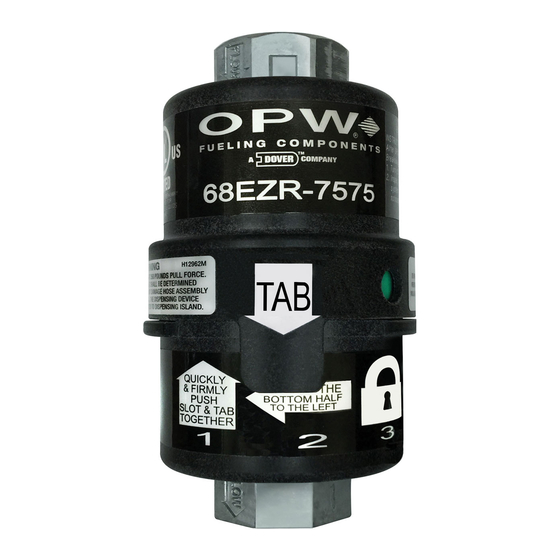
68EZR RECONNECTABLE BREAKAWAY
FOR THE 68EZR–7575
IMPORTANT SAFEGUARDS:
• For your protection, please read these safety
instructions completely before installing and
operating this equipment.
• Keep this manual on file for future reference.
• This manual contains material that may be
required to be on site at all times to comply
with various authorities.
• Carefully observe and adhere to all warnings,
precautions and instructions for this equipment.
WARNINGS:
Failure to comply with the following
warnings could result in property damage,
injury or death.
• Dispensing system must be tested to determine if a
separation force of 350 pounds would damage it.
INSTALLATION
The OPW 68EZR is manufactured to properly function up to a disengagement
force of 350 lb (158 kg). Per U.L. requirements, after installation of the new OPW
68EZR, it must be tested to verify that a pull force of 350 pounds will not damage
the hose assembly or dispensing device (See Figure A for test). The dispensing
device must be securely bolted to the dispensing island.
Valve should be installed according to the directional "flow-arrows" located on the
wrench-flats.
PULL FORCE TEST: (SEE FIGURE A)
Attach a spring scale to the location where the breakaway will be installed. Apply
a 350 lb (158 kg) pull force at various angles and check the emergency valves,
dispenser and hose assembly.
Figure A
Rope
Force
350 lb (158 kg)
Although the valve can be installed with flow in either direction, it is
very important that the OPW 68EZR be installed according to the directional
"flow-arrows" located on the wrench-flats of the inlet and discharge ports of the
OPW 68EZR breakaway bodies. This is suggested for ease of reconnection and
weather protection. Dispensers with high hanging-hose and low-hose
applications are also suitable for this method.
1" or 3/4" NPT
Female Nipple
• Dispenser must be securely attached to the dispensing
island.
• Keep gasoline / fuel away from your eyes and skin.
• Keep gasoline / fuel out of reach of children
• Do not use power tools (Class I Division I and Class I
Division II) during installation process and maintenance
of equipment.
• CHEMICAL EXPOSURE HAZARD: Always wear
appropriate safety equipment during installation or
maintenance of equipment.
• FIRE HAZARD: Do not install an unlisted ad/billboard or
other unlisted after-market device on any breakaway.
Doing so may interfere with proper operation of the
breakaway. Breakaway may not separate properly,
causing a fuel spill, property damage, injury or death.
Reference: sensitivity test per Underwriters Laboratories
specification UL842.
SIDE HOSE CONNECTION: (SEE FIGURE B)
Install the OPW 68EZR downstream of the hose retractor clamp. Install a
9" (230 mm) minimum length hose or OPW 66H-0075 between OPW 68EZR
and nozzle. Total length of hoses and breakaway valve is not to exceed local,
state or federal codes.
OVERHEAD HOSE CONNECTION: (SEE FIGURE C)
Install the OPW 68EZR with a 9" (230 mm) minimum length hose or OPW
66H-0075 onto dispenser as shown. Install hose between OPW 68EZR and nozzle.
Total length of hoses and breakaway valve is not to exceed local, state or federal
codes. If dispenser is equipped with a hose retractor, install the OPW 68EZR
downstream of the hose retractor clamp.
IMPORTANT
Use wrench on wrench-flats to attach breakaway to the hose.
DO NOT use wrench or clamp on the upstream cover to install the breakaway.
DO NOT use the upstream cover to thread breakaway on the hose.
Doing so may interfere with proper operation of the breakaway.
DO NOT use thread or Teflon® tape. Use U.L. recognized pipe sealant on
threaded connections.
208080 July 2014
Advertisement

Subscribe to Our Youtube Channel
Related Manuals for Dover OPW 68EZR


Summary of Contents for Dover OPW 68EZR
- Page 1 Valve should be installed according to the directional “flow-arrows” located on the OVERHEAD HOSE CONNECTION: (SEE FIGURE C) wrench-flats. Install the OPW 68EZR with a 9” (230 mm) minimum length hose or OPW 66H-0075 onto dispenser as shown. Install hose between OPW 68EZR and nozzle. PULL FORCE TEST: (SEE FIGURE A) Total length of hoses and breakaway valve is not to exceed local, state or federal Attach a spring scale to the location where the breakaway will be installed.
- Page 2 BOTTOM HALF SLOT & TAB TO THE LEFT Your OPW 68EZR is now reconnected. Pressurize the dispensing system and check TOGETHER for leakage as described in step 3. If the system was not damaged and a proper reconnection has been made, you may resume normal operation of the dispensing unit.
- Page 3 208080 July 2014 OPW STANDARD PRODUCT WARRANTY / OPW TERMS & POLICIES- Notice: FlexWorks by OPW, Inc., VAPORSAVER™ and all other OPW products must be used in compliance with all applicable federal, state, provincial and local laws, rules and regulations. Product selection is the sole responsibility of the customer and/or its agents and must be based on physical specifications and limitations, compatibility with the environment and material to be handled.
Need help?
Do you have a question about the OPW 68EZR and is the answer not in the manual?
Questions and answers