Table of Contents
Advertisement
Operation &
Maintenance
Manual
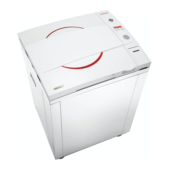
Laboratory Vertical Steam Sterilizers
Including Fast Cooling System
models 3840, 3850, 3870
ELV/WR/C/PV/BH/F-D
Cat. No. MAN205-0448002EN Rev F
Tuttnauer Europe b.v., Hoeksteen 11, 4815 PR, Breda, P.O. Box 7191, 4800 GD
Breda, Netherlands. +31/76-5423510, Fax: +31/76-5423540
Advertisement
Table of Contents

Related Manuals for Tuttnauer 3840 ELV


Summary of Contents for Tuttnauer 3840 ELV
- Page 1 Operation & Maintenance Manual Laboratory Vertical Steam Sterilizers Including Fast Cooling System models 3840, 3850, 3870 ELV/WR/C/PV/BH/F-D Cat. No. MAN205-0448002EN Rev F Tuttnauer Europe b.v., Hoeksteen 11, 4815 PR, Breda, P.O. Box 7191, 4800 GD Breda, Netherlands. +31/76-5423510, Fax: +31/76-5423540...
-
Page 3: Table Of Contents
TABLE OF CONTENTS PARAGRAPH PAGE NO. GENERAL......................4 1.1 Introduction....................4 1.2 Incoming Inspection................6 1.3 Warranty.....................6 1.4 Warranty Statement.................6 1.5 Accessories ....................7 SAFETY INSTRUCTIONS .................8 TECHNICAL DATA ..................10 3.1 Storage Conditions ................10 3.2 Operating Conditions................10 3.3 Directives and Standards..............10 3.4 Environment Emission Information........... - Page 4 6.2 Entering the main menu ...............57 6.3 Directories and subdirectories ............59 6.4 Cycle Parameters (Custom program = duplicate cycle) ....59 6.5 System Parameters ................67 6.6 Maintenance .................... 70 SCREENS......................76 7.1 Screens following a complete successfully cycle – "Cycle Ended" ........................
- Page 5 TABLE OF CONTENT (Cont.) DRAWINGS PAGE NO. FRONT VIEW (STANDARD CONFIGURATION) ........15 FRONT VIEW (WR CONFIGURATION) ............. 16 FRONT VIEW (FAN CONFIGURATION)............ 17 REAR VIEW (STANDARD CONFIGURATION) ......... 18 REAR VIEW (WR CONFIGURATION) ............19 OVERALL DIMENSIONS (STANDARD CONFIGURATION, mm) ..... 20 OVERALL DIMENSIONS (WR CONFIGURATION, mm) ......
-
Page 6: General
GENERAL Introduction A computerized control unit ensuring a fully automatic sterilization cycle controls the autoclave. The temperature and pressure are controlled through sensors placed inside and outside the media container or bottles. The sterilizer is fully automatic with a choice of 10 programs, eliminating any need for operator intervention during a cycle program 7 are for vacuum test only). - Page 7 Only technical personnel having proper qualifications, holding technical documentation and adequate test instrumentation are authorized to undertake repair or service. Available optional configurations Models of 3870 ELV model range -D are laboratory sterilizers designed especially for the sterilization of instruments, liquids, and other materials in hospital laboratories, medical laboratories, research institutes, food laboratories and pharmaceutical facilities.
-
Page 8: Incoming Inspection
All Tuttnauer products are carefully inspected prior to shipment and all reasonable precautions are taken in preparing them for shipment to assure safe arrival at their destination. -
Page 9: Accessories
Tuttnauer Europe b.v., Hoeksteen 11, 4815 PR, Breda, P.O. Box 7191, 4800 GD Breda, Netherlands. +31/76- 5423510, Fax: +31/76-5423540, E-mail: info@tuttnauer.nl Tuttnauer USA Co., Ltd., 25 Power Drive Hauppauge, NY 11788, USA : (800) 624 5836, (631) 737 4850, Fax: (631) 737 0720 e-mail:info@tuttnauerUSA.com. -
Page 10: Safety Instructions
SAFETY INSTRUCTIONS The autoclave has unique characteristics. Please read and understand the operation instructions before first operation of the autoclave. The following issues may require instructions guidance provided by the manufacturer: how to operate the autoclave, the door safety mechanism, the dangers involved in circumventing safety means, how to ensure that the door is closed, and how to select a correct sterilization program. - Page 11 On closing the autoclave's door, make sure it is properly locked before activating. Before withdrawing baskets, wear heat resistant gloves. Before opening the door, verify that there is no pressure in the chamber (chamber pressure gauge is located on the autoclave's front panel or door, depends on model).
-
Page 12: Technical Data
TECHNICAL DATA Storage Conditions The packed or unpacked autoclave shall be retained in indoor conditions! Operating Conditions The autoclave is intended to work in ‘indoor’ conditions only. Only autoclavable materials shall be used. The environment shall not exceed an ambient temperature range of 5ºC (41ºF)-40ºC (104ºF) and a relative humidity of 85% respectively. -
Page 13: Environment Emission Information
4. EN 285:2006 ― Sterilization, Steam sterilizers, Large sterilizers 5. IEC/UL 61010A-1 ― electrical equipment for laboratory use; general requirements. IEC 61010-2-040 ― particular requirements for sterilizers and washer disinfectors used to treat medical materials. ISO 17665 ― 1:2006 Sterilization of health care products moist heat. -
Page 14: Specifications
Heaters power (W) 3300 Protection against electrical shock Class I Degree of protection by enclosure IP31 Specifications MODEL PROPERTIES 3840 3850 3870 Chamber diameter 380 (15”) 380 (15”) 380 (15”) Chamber depth 400 (15.8”) 480 (18.9”) 680 (26.8”) 52 liters. (11 65 liters. -
Page 15: Utilities
Utilities Electrical utility 3.8.1 Recommended Power Switch box Circuit Breaker 208-220V (3 Ph + Earthing) 400V(3 Ph + Neutral + Earthing) 230V 1ph Frequency 50/60Hz 3.8.2 Other Utilities Compressed Air (ELVC 1/2" 3-4 Bar (44-58 psi) only) Tap water 1/2", 2-3 Bar (29-44 psi) Mineral free water 1/2", 2-3 Bar (29-44 psi) 2"... -
Page 16: Symbol Description
Symbol Description Caution! Consult accompanying documents Caution! Hot surface. Caution! Hot steam. Protective earth (Ground) On-Off Page 14... -
Page 17: Front View (Standard Configuration)
FRONT VIEW (STANDARD CONFIGURATION) Description Front leg Rear leg Left service door Left service door grip Left service door lock Door cover Pressure gauge Display Keyboard Printer cover Paper slot and paper cutter USB socket RJ45 connector Main switch Printer Page 15... -
Page 18: Front View (Wr Configuration)
FRONT VIEW (WR CONFIGURATION) Description Front leg (with brakes) Rear leg Front service door Right service door grip Right service door lock Door cover Pressure gauge Display Paper slot and paper cutter Printer cover Keyboard USB socket RJ45 connector Printer Main switch Page 16... -
Page 19: Front View (Fan Configuration)
FRONT VIEW (FAN CONFIGURATION) There is a configuration equipped with a fan that allows to shorten the cooling operation. The fan is located on the door of the autoclave. Page 17... -
Page 20: Rear View (Standard Configuration)
REAR VIEW (STANDARD CONFIGURATION) Description Drain outlet Mineral free water inlet Compressed air inlet Cavitation port Power supply electrical cord Cut-off Fan grill Safety Valve Circuit breaker Ground connector City (tap) water inlet for cooling coil Air pressure gauge Air pressure regulator Page 18... -
Page 21: Rear View (Wr Configuration)
REAR VIEW (WR CONFIGURATION) Description Rear wheel Water reservoir drain Water reservoir overflow Power supply electrical cord Cut-off Fan grill Safety valve Circuit breaker Left service door lock Back service door handle Water reservoir door handle Left service door handle Front wheel (with brakes) Page 19... -
Page 22: Overall Dimensions (Standard Configuration, Mm)
OVERALL DIMENSIONS (STANDARD CONFIGURATION, mm) Page 20... -
Page 23: Overall Dimensions (Wr Configuration, Mm)
OVERALL DIMENSIONS (WR CONFIGURATION, mm) Page 21... -
Page 24: Description Of Operation
3.10 Description of Operation 3.10.1 Air removal (optional) IN PV (pre-vacuum) models, the autoclave is equipped with a vacuum pump for performing the air removal stage. Before the sterilization stage, one or two vacuum pulses (according to the cycle) are built in the chamber. - Page 25 Unsealed bottles (cooling without compressed air) On completion of sterilization, steam is exhausted from the chamber at a slow rate. When chamber pressure goes down to atmospheric pressure, water starts flowing through the cooling coil mounted around the outer side of the chamber. On conclusion of the cycle the water flow is stopped automatically, process is completed and it is possible to open the door and take out the sterilized goods from the chamber.
-
Page 26: Water Quality
3.11 Water Quality 3.11.1 Water for Steam Generation The distilled or mineral – free water supplied to the autoclave should have the physical characteristics and maximum acceptable level of contaminants indicated in the table below: Physical Characteristics and Maximum acceptable contaminants levels in steam for sterilizers (According to EN 13060:2004). -
Page 27: Safety Features
3.11.3 Reverse Osmosis A Reverse Osmosis (RO) system may be used to improve the quality of the water used to generate steam in the autoclave chamber. In RO, the water is forced through a semi-penetrable membrane, which filters out contaminants to a high degree of efficiency. -
Page 28: Control Panel
CONTROL PANEL CONTROL PANEL DRAWING Description Display Keypad Printer Page 26... -
Page 29: Description And Functions Of The Front Panel Keyboard
Description and Functions of the Front Panel Keyboard The front panel is composed of 3 sections: 1. Display screen. 2. Keypad. 3. Printer 4.1.1 Display screen The display is a LCD panel used to display the current status of the autoclave while using Operational Messages and Error Messages. - Page 30 4.1.2 Keypad The keypad consists of three keys as described below: UP key This key has the following functions: In the menu directories: o This key enables the operator to browse through the cycles. In the directories available: o When the cursor is blinking on a number, the UP ▲...
-
Page 31: Displayed Error Messages / Symbols
4.1.3 Printer The printer is an optional device. It prints the detailed history of each cycle performed by the autoclave. The printing is on thermal paper with 24 characters per line and records the sterilization cycle information for subsequent consideration. Displayed Error Messages / Symbols The failures are divided into two categories. -
Page 32: Displayed Operational Messages / Symbols
Displayed operational messages / Symbols Message / Message / Symbol Symbol Required Action Description Name This symbol is displayed Close the door. when the door is open. This symbol is displayed when there is water in Repeat the cycle chamber. Door is This message is open... -
Page 33: Sterilization Programs
5. STERILIZATION PROGRAMS The autoclave offers ten sterilization programs as follows: Sterilization Programs Temp. models models models only only only Icon Program Description 134°C Glass (273F) 121°C Plastic (250F) 121°C Liquid A (250F) 121°C Liquid B – Waste* (250F) Liquid A – 121°C √... -
Page 34: Program 1: Glass
Sterilization Programs Temp. models models models only only only Icon Program Description Bio Hazard √ Liquids* (250F) √ Vacuum test (PV only)* 80 °C Warm-Up* 176F) 80 °C Isothermal* 176F) *These programs are optional During the process, the stages of the cycle will be displayed on the screen: The stages names are as follows: Start Pulse Low (PV models only) - Page 35 Program 2: Plastic For glass instruments, when the manufacturer recommends autoclaving at temperatures of 134C (273F). Drying stage is available for PV (pre- vacuum) models only. Nominal parameters default settings Sterilization temperature: 134C (273F). Sterilization time: 3 minutes. ...
-
Page 36: Program 2: Plastic
Program 2: Plastic For plastic and other delicate instruments, when the manufacturer recommends autoclaving at temperatures of 121C (250F). Drying stage is available for PV (pre-vacuum) models only. Nominal parameters default settings Sterilization temperature: 121C (250F) Sterilization time: 15 minutes ... -
Page 37: Program 3: Liquid A
Program 3: Liquid A For liquids when the manufacturer recommends autoclaving at temperatures of 121C (250F) for 15 minutes. Cautions! Both PT100 temperature sensors must be inside the bottles. For proper sterilization, fill the bottles with approximately the same amount of liquid. Nominal parameters default settings ... -
Page 38: Program 4: Liquid B - Waste
Program 4: Liquid B – Waste For liquids when the manufacturer recommends autoclaving at temperatures of 121C (250F) for 30 minutes, such as liquid waste. Cautions! Both PT100 temperature sensors must be inside the bottles. For proper sterilization, fill the bottles with approximately the same amount of liquid. -
Page 39: Program 5: Liquid A - Cooling (C - Cooling Models Only)
Program 5: Liquid A – Cooling (C – cooling models only) For liquids when the manufacturer recommends autoclaving at temperatures of 121ºC (250F). for 15 minutes. Cautions! Both PT100 temperature sensors must be inside the bottles. For proper sterilization, fill the bottles with approximately the same amount of liquid. -
Page 40: Program 6: Liquid B - Waste Cooling (C - Cooling Models Only)38
Program 6: Liquid B – Waste Cooling (C – cooling models only) For liquids when the manufacturer recommends autoclaving at temperatures of 121ºC (250F) for 30 minutes, such as liquid waste. Cautions! Both PT100 temperature sensors must be inside the bottles. For proper sterilization, fill the bottles with approximately the same amount of liquid. -
Page 41: Program 7: Bio Hazard 1 (Bh, Bio-Hazard Models Only)
Program 7: Bio Hazard 1 (BH, bio-hazard models only) All exhaust from the chamber before completion of the Sterilization stage is performed through the bio-hazard filter. For instruments, when the manufacturer recommends autoclaving at temperatures of 134C (273F) for 30 minutes. Drying stage is available for PV (pre- vacuum) models only. -
Page 42: Program 8: Bio Hazard 2 (Bh, Bio-Hazard Models Only)
(PV, pre-vacuum models only) Drying: vacuum is built up and the air pump is working. Ending: The system checks that End temperature and End pressure have been reached, and then releases the door. Program 8: Bio Hazard 2 (BH, bio-hazard models only) All exhaust from the chamber before completion of the Sterilization stage is performed through the bio-hazard filter. -
Page 43: Program 9: Bio Hazard Liquids (Bh, Bio-Hazard Models Only)
cycle. To remove such water, press Start and repeat the cycle. If the problem persists, call for service. (PV, pre-vacuum models only) Drying: vacuum is built up and the air pump is working. Ending: The system checks that End temperature and End pressure have been reached, and then releases the door. -
Page 44: Program 10: Vacuum Test (Pv, Pre-Vacuum Models Only)
Cooling: N/A Slow Exhaust: Steam is exhausted from the chamber at a slow rate, until it reaches the pressure of 30 kPa above the ambient pressure. Then steam is exhausted out of the chamber at a fast rate until pressure decreases to ambient pressure. -
Page 45: Program 11: Warm-Up
At the end of the test, the printer records the results. The pressure at the end of the test is referred to as P3. The rate of change of P3-P2 shall not exceed 0.13 kPa/min.). 5.11 Program 11: Warm-Up Pre-warming the chamber at 80C (176F) without drying. -
Page 46: Program 12: Isothermal
5.12 Program 12: Isothermal For liquids when the manufacturer recommends autoclaving at 60-100C (140-212F) with no drying. Recommending for melting of agar, pasteurization etc. Caution! This is not a sterilization program! Put one PT100 inside the bottle, leave the second one hanging in the chamber outside the bottle (see below). - Page 47 Cooling: N/A. Fast Exhaust: the steam is exhausted out of the chamber at a fast rate until pressure decreases to ambient pressure. Drying: N/A Ending: The system checks that End temperature and End pressure have been reached, and then releases the door. Note: Some water may remain in the chamber.
-
Page 48: Checking And Changing Parameters And Other Data
CHECKING AND CHANGING PARAMETERS AND OTHER DATA When the system is ready, enter the QUICK OPTIONS screen by pressing the UP and DOWN keys simultaneously. Note: To exit every screen: move the cursor to Exit by pressing UP or DOWN keys and then press START/STOP key. - Page 49 2. Move the cursor to Add extra dry time. 3. Press the START/STOP key. 4. The following screen will be displayed: 5. Move the cursor to the required item and press START/STOP key. 6. The time shown on the screen will be added to the current value and you will return to the cycle main screen.
- Page 50 In order to return to the default dry time value, enter the Add Extra Dry time screen and choose zero value. See the screen below. 6.1.2 Export to USB This directory includes two subdirectories (see below) Page 48...
- Page 51 1. Move the cursor to Export to USB 2. Press the START/STOP key. 3. The following screen will be displayed: Export all settings to USB device This subdirectory allows exporting all settings to USB device 1. Insert the USB device into the USB socket. 2.
- Page 52 In order to exit this subdirectory, press the START/STOP key. All cycles history, Last 10 cycles, Last 50 cycles. These subdirectories enable to export history to USB device. 4. Insert the USB device into the USB Socket 5. Move the cursor to the required item and press the START/STOP key.
- Page 53 9. Move the cursor to Print cycles. 10.Press the START/STOP key. 11.The following screen will be displayed: 12.Move the cursor to the required item and press START/STOP key 13.The cycle report will be printed -- see 8.1 Printer Output. 14.In order to exit this subdirectory, press the UP and DOWN keys simultaneously.
- Page 54 1. Move the cursor to Version Information. 2. Press the START/STOP key. 3. The following screen will be displayed: 1. To enter the sub directories, move the cursor by pressing UP or DOWN keys to the required item and press START/STOP.
- Page 55 Utilities – Utilities – Holds general functionality which is used by the logic section and the GUI section e.g.: converting function display different pressure or temperature units, languages types etc. Operational System – Microsoft Windows CE. Version 6.0. Software DLL size Major Minor Automatic...
- Page 56 This subdirectory enables the operator to see the previous version information. The previous version information screen has the same look as the current version information screen. 6.1.5 Start cycle by clock This subdirectory enables the operator to postpone the operation by a pre-set time. 4.
- Page 57 Enabling the START CYCLE BY CLOCK To increase or decrease the time use the UP or DOWN keys. To move the cursor from one digit to another press the START/STOP key. After changing the time move the cursor to Enabled Confirm the START CYCLE BY CLOCK by pressing UP or DOWN keys.
- Page 58 When entering the SET DATE AND TIME screen, the time and date are displayed. The cursor is blinking on the "second" digit. The time is displayed in the upper row in the form "HH:MM:SS". The hour range is 24 hour (i.e. from "0" to "24") The date is displayed in the lower row in the form "DD: MMM: YYYY".
-
Page 59: Entering The Main Menu
Entering the main menu When the system is ready, enter the QUICK OPTIONS screen pressing DOWN keys simultaneously. Note: To exit the QUICK OPTIONS screen: move the cursor to Exit by pressing UP or DOWN keys and then press START/STOP key. ... - Page 60 0000 is displayed on the screen with the cursor blinking on the right digit. To increase or decrease the digits, press the UP or DOWN keys. After changing the code to 0001 move the cursor to Set by pressing the START/STOP key. When Set is blinking, press the UP or DOWN keys to enter the MAIN MENU of the autoclave.
-
Page 61: Directories And Subdirectories
Directories and subdirectories The operator (Admin) may perform the following: DIRECTORY SUBDIRECTORY Purge Create Pulse Keep Heat Heating Sterilization Cycle Parameters Cooling Exhaust Drying Ending Global Print Rate All System Parameters Print Rate Sterilization Screen Saver Export gain offset to USB Reset atmospheric pressure Maintenance Printer test... - Page 62 Sterilization Time Cool Mode Cooling Cool End Temperature Cool Exhaust Rate Exhaust Exhaust Mode Dry Time Drying Dry Air On Pressure Dry Air Off Pressure End Temperature Ending Exhaust Mode Bio Hazard Multiple Cycles Global Multiple Cycles Gap Jacket Temperature Jacket Mode These subdirectories enable to see and change the cycle parameters.
- Page 63 Typical display for Purge subdirectory Choose and enter Purge Time. SET PARAMETER screen will be displayed Set the required value, move to Set and press UP or DOWN keys to confirm the parameter value. In order to exit move the cursor to Exit and press UP or DOWN keys Purge Temperature Repeat the action mentioned in temperature...
- Page 64 Set the required value, move to Set and press UP or DOWN keys to confirm the parameter value. In order to exit move the cursor to Exit and press UP or DOWN keys Pulse A Stay Time Repeat the action mentioned in Pulse A Count above.
- Page 65 Choose and enter Temperature 1 Stay. SET PARAMETER screen will be displayed Set the required value, move to Set and press UP or DOWN keys to confirm the parameter value. In order to exit move the cursor to Exit and press UP or DOWN keys Temperature 1 Stay Time Repeat the action mentioned in temperature...
- Page 66 Typical display for Cool Mode subdirectory Choose and enter Cool Mode SET PARAMETER screen will be displayed Set the required value, move to Set and press UP or DOWN keys to confirm the parameter value. In order to exit move the cursor to Exit and press UP or DOWN keys Cool End Temperature Repeat the action mentioned in 7.4.4.1 Cool...
- Page 67 SET PARAMETER screen will be displayed Set the required value, move to Set and press UP or DOWN keys to confirm the parameter value. In order to exit move the cursor to Exit and press UP or DOWN keys 6.4.8 Drying Dry Time Typical display for Dry Time subdirectory...
- Page 68 End Temperature Typical display for End Temperature subdirectory Choose and enter End Temperature SET PARAMETER screen will be displayed Set the required value, move to Set and press UP or DOWN keys to confirm the parameter value. In order to exit move the cursor to Exit and press UP or DOWN keys Global 6.4.10...
-
Page 69: System Parameters
Multiple Cycles Gap Repeat the action mentioned in 7.4.8.1 Bio Hazard Jacket Temperature Repeat the action mentioned in 7.4.8.1 Bio Hazard System Parameters This directory includes three subdirectories The following screen will be displayed when entering SYSTEM PARAMETERS directory: In order to enter to the sub directories move the cursor by pressing UP or DOWN keys to the required item and press START/STOP key In order to exit this screen follows one of the next:... - Page 70 6.5.1 Print Rate All This subdirectory allows changing the printing rate during the whole cycle except sterilization stage. 1. To increase or decrease the digits, press the UP or DOWN keys. 2. After changing the value move the cursor to Set by pressing the START/STOP key.
- Page 71 1. To increase or decrease the digits, press the UP or DOWN keys. 2. After changing the value move the cursor to Set by pressing the START/STOP. 3. When Set is blinking, press the UP or DOWN keys in order to confirm changes and return to the previous screen.
-
Page 72: Maintenance
Maintenance This directory includes four subdirectories The following screen will be displayed when entering MAINTENANCE directory: 1. In order to enter to the sub directories move the cursor by pressing UP or DOWN keys to the required item and press START/STOP key 2. - Page 73 6. In order to exit this screen and return to MAINTENANCE directory press START/STOP key. 7. In order to exit the MAINTENANCE directory follows one of the next: Move the cursor to Exit with the UP or DOWN keys select pressing START/STOP key.
- Page 74 3. On the cycle main menu, choose cycle parameters. 4. Press the START/STOP key 5. The following screen will be displayed: 6. Choose Keep Heat. 7. On the screen that appears, choose the required item. Page 72...
- Page 75 8. Change the required parameter. 9. To increase or decrease the digits, press the UP or DOWN keys. 10. After changing the value move the cursor to Set by pressing the START/STOP key. 11. When Set is blinking, press the UP or DOWN keys in order to confirm changes and return to the previous screen.
- Page 76 When pressing START/STOP key on the Printer Test item the printer will print out the following print out: Cycle errors: None Canceled By User Door is open Analog Input Error I/O Card Failed Power Down Invalid Parameter Value No Water Heat Time Error Vacuum Time Error Pressure Time Error...
- Page 77 6.6.5 Print All Gain and Offset This subdirectory enables the operator to print all the gain and offset values. When pressing START/STOP key on the Print all gain and offset item the printer will print out the following: Drain Temperature G:000.0400;O:-004.0000 Chamber Temperature G:000.0400;O:-004.0000...
-
Page 78: Screens
SCREENS Screens following a complete successfully cycle – "Cycle Ended" 1. System Ready 2. Insert Water 3. Heat 4. Sterilization 5. Exhaust 6. Ending 7. Cycle Ended Screens following aborted cycles after complete sterilization stage The sterilization phase ended successfully – cycle ended and the reason of failure is displayed For example the next two scenarios: 7.2.1... -
Page 79: Screens Following A Fail Cycle
Screens following a fail cycle: In this case, the display becomes yellow, a warning sign and the reason of failure will be displayed. For example, the next two scenarios: 7.3.1 Failure according to Pressure Time Error 7.3.2 Failure according to Cancellation by user before complete sterilization stage When "Cycle Failed"... -
Page 80: Printer
PRINTER Printer Output The printing is on thermal paper with 24 characters per line and contains the following information: Date: Time: Ser. Num: Model: Version: Cycle Num: Cycle: Dry Time: Ster Temp: ... - Page 81 PRINTER OUTPUT DESCRIPTION Operator: ____________ To be filled in manually by operator Time: 12:14:47 Time sterilization cycle ended Cycle Ended 00:24:43 101.3 099.7 Cycle finished time E 00:23:43 107.0 107.4 The time, temperature and pressure during exhaust E 00:22:08 134.5 311.9 The time, temperature and pressure during exhaust CLK 2:...
-
Page 82: Printer Handling
Printer Handling 8.2.1 Maintenance Wipe off the soiling on the printer surface with a dry soft cloth with a weak neutral detergent. After that, wipe the printer with a dry cloth. 8.2.2 Setting paper PLUS II Front view 1-Paper mouth 2-STATUS Led 3-OPEN key (for paper roll compartment opening) - Page 83 Open the printer's cover door (1) by pulling it up (see Fig. 2). Fig. 2 Press the OPEN key to open the printer cover as shown (see Fig. 3/1). Handle the paper cutter carefully not to cut your hand. Place the paper roll making sure it unrolls in the proper direction as shown (see Fig.
- Page 84 8.2.3 Treating the thermal papers: Store the papers in a dry, cool and dark place. Do not rub the papers with hard substance. Keep the papers away from organic solvent. Cautions Never disassemble the printer. Failure to follow this instruction may cause overheating or burning of the printer or the AC adapter.
-
Page 85: Preparation Before Sterilization
PREPARATION BEFORE STERILIZATION The purpose of packaging and wrapping of items for sterilization is to provide an effective barrier against sources of potential contamination in order to maintain sterility and to permit aseptic removal of the contents of the pack. Packaging and wrapping materials should permit the removal of air from the pack, penetration of the sterilizing water vapor into the pack and removal of the sterilizing vapor. -
Page 86: Liquids
6. Place instruments with ratchets opened and unlocked or clipped on the first ratchet position. 7. Disassemble or sufficiently loosen multiple-part instruments prior to packaging to permit the sterilizing agent to come into contact with all parts of the instrument. 8. - Page 87 Page 85...
-
Page 88: Operation
OPERATION 10.1 Filling the water reservoir (WR configuration only) Remove the water reservoir cover (See Rear view, WR Configuration). Pour distilled water into the reservoir until it reaches the cooling coil (see the figure below). The water quantity is approx. 28 liters (7.4 US gal.). Use only water having the characteristics as per table in sec 3.11.1 Tap water may clog the system. -
Page 89: Opening The Door
The door is equipped with an electrical cylinder. This electrical cylinder perform the automatic opening and closing of the door. 10.3 Opening the door In order to open the door, follow the next steps: When the door is closed the screen below will be displayed: Press the key in order to open the door The following screen will be displayed:... -
Page 90: Loading
10.4 Loading Load the autoclave properly according to instructions in sec. 9. PREPARATION BEFORE STERILIZATION. Select the program. UP key: next program. DOWN key: previous program. Verify that you chose the required program. 10.5 Closing the door In order to close the door, follow the next steps: When the door is open, the screen below will be displayed: In order to close the door push the door to the wall of the... -
Page 91: Starting Cycle
When the door is properly closed, open door symbol replaced by the message "System Ready" and the following screen will be displayed: 10.6 Starting cycle Start the cycle by pressing the START/STOP key. If your autoclave supports CFR 21 part 11 standard, perform the following procedure: SELECT USER screen will be displayed: Enter the Enter Code screen by moving the... -
Page 92: Unloading
0000 is displayed on the screen with the cursor blinking on the right digit. To increase or decrease the digits, press the UP or DOWN keys. Set your password, then move the cursor to Set by pressing the START/STOP key. When Set is blinking, press the UP or DOWN keys to return to the program screen. -
Page 93: Stopping The Process And Cancelling The Error Message
colour of the sterilization indicators turned to the required colour. 10.8 Stopping the process and cancelling the ERROR message It is possible to stop the program while the autoclave is operating. Pressing the START/STOP key at any stage of the process stops the operation. -
Page 94: Door Safety System
For proper sterilization - Do not overload the chamber. Only autoclavable products shall be used; please refer to the manufacturer instructions for sterilization of unknown materials or instruments. 10.11.2 Loading Correct loading of the autoclave is essential to successful sterilizing for several reasons. Efficient air removal from the chamber and the load will permit effective steam penetration and saturation, and allow proper drainage of condensate. -
Page 95: Pressure Switch
Door opening: The user presses a key to open the door. The control system operates the electrical cylinder that unlocks the door. When the door is unlocked, a micro switch indicates that the door is unlocked and stops the electrical cylinder. 11.2 Pressure switch The autoclave is equipped with a NC 10 kPa (1.4 psi) pressure... -
Page 96: Service And Maintenance
SERVICE AND MAINTENANCE 12.1 Preventive Maintenance The maintenance operations described in this chapter must be fulfilled periodically in order to keep the autoclave in good working condition and to reduce the breakdown time to a minimum. The user’s maintenance personnel, according to the following instructions can easily execute these operations. -
Page 97: Checking The Safety Valve
1. Every 6 months replace the air filter, (if installed) (to be done by an authorized technician). 2. Once a year check and tighten the piping joints to avoid leakage (to be done by an authorized technician). 1. Checking the water reservoir, piping, plastic parts and electric wires. - Page 98 Pressure-Regulating Nut Rear Wall 12.2.2 ASME-approved type safety valve Operate the sterilization cycle according to the manual. Allow a pressure of approximately 200 kPa (29-psi) to build up in the chamber. Operate the safety valve by pulling the ring of the safety valve using a tool, i.e.
-
Page 99: Draining The Reservoir
Safety valve ring 12.3 Draining the Reservoir CAUTION! Before starting, Make sure that the electric cord is disconnected and there is no pressure in the autoclave. The drain valve is located on the bottom of the water reservoir (See REAR VIEW (WR CONFIGURATION). The function of the drain valve is to drain the water reservoir. -
Page 100: Troubleshooting
TROUBLESHOOTING This troubleshooting chart enables the user to solve minor malfunctions, prior to contacting our service department. Only technical personnel having proper qualifications and holding technical documentation (including a technician manual) and adequate information are authorized to service the apparatus. Message / Symbol / Failure Description... - Page 101 Message / Symbol / Failure Description Corrective Action Problem This message is displayed if the temperature drops for more than Low Temp 1 second below the sterilization Perform a new cycle. temperature during sterilization cycle. This message is displayed if the temperature raises 7°F (4°C) High Temp above sterilization temperature...
- Page 102 Message / Symbol / Failure Description Corrective Action Problem This message is displayed if the High system cannot reach preset Pressure pressure within 10 minutes from Perform a new cycle. (Exhaust) the beginning of the exhaust stage. This message is displayed if the system cannot reach the required Pressure Verify that the autoclave is...
- Page 103 Message / Symbol / Failure Description Corrective Action Problem Please call defined by "cycle counter" for service parameter. This message is displayed if Turn on the autoclave and power down has occurred wait until the autoclave is Power during the cycle. (this message ready (reaches the safe Down will print out in the printer after...
-
Page 104: Baskets And Containers
BASKETS AND CONTAINERS Container for waste products High Basket Low Basket Stainless steel container for Type Stainless steel wire baskets waste products, with vent holes Model Dia. x Height (mm) Capacity Dia. x Height (mm) Capacity 357 x 220 366 x 330 3840 357 x 330 366 x 220... -
Page 105: Spare Parts List
SPARE PARTS LIST Description Cat. No. Cap for ¼” strainer FIL175-0027 Strainer element FIL175-0046 Teflon gasket 4 mm GAS082-0008 ACCESSORIES Description Cat. No. Printer, PLUSII-S2B-0004 THE002-0052 High BSK387-0001 Stainless steel wire basket BSK387-0002 Stainless steel High BSK387-0005 container for waste products, with vents BSK387-0003 holes...
Need help?
Do you have a question about the 3840 ELV and is the answer not in the manual?
Questions and answers