
Related Manuals for SMC Networks ZVB Series


Summary of Contents for SMC Networks ZVB Series
- Page 1 Document No: ZVB-OM00201 PRODUCT NAME Desktop Duster Box MODEL/ Series/ Product Number ZVB Series Applicable model: ZVB40...
-
Page 2: Table Of Contents
1.5 Operation Method ............. 7 1.6 Operation step (with photoelectric sensor) .... 8 1.7 Removal of side cover ..........9 2. Desktop Duster Box/ ZVB Series ......10 2.1 Specifications............10 2.2 How to Order ............10 2.3 Construction ............11 2.4 Dimensions ............. -
Page 3: Safety Instructions
ZVB Series Safety Instructions These safety instructions are intended to prevent hazardous situations and/or equipment damage. These instructions are categorized into three groups, "Caution", "Warning" and "Danger" depending on the level of hazard and damage, and the degree of emergency. They are all important notes for safety and... - Page 4 ZVB Series Safety Instructions Caution 1. The product is provided for use in manufacturing industries. The product herein described is basically provided for use in manufacturing industries. If the product is being considered for use in other industries, consult SMC beforehand and exchange specifications or a contract if necessary.
- Page 5 ZVB Series Safety Instructions Selection Warning 1. Use within the specified voltage and temperature range. Operation with a voltage other than that specified can cause malfunction, damage to the product, electric shock or fire. 2. Use clean compressed air as fluid.
-
Page 6: How To Operate
1. How to Operate 1.1 Outline 1. This is equipment used to remove dust that is stuck to a workpiece due to static and to remove static electricity and collect dust to prevent dust from sticking to the workpiece again. 2. -
Page 7: Wiring Of The Dc Plug
1.3 Wiring of the DC plug If the AC adapter is not selected as an option, wire the attached DC plug with the procedure below. (1) Remove the cover from the DC plug body. Plug body Cover (2) Strip the end of the lead wires by 3 to 4 mm, and insert the lead wires into the cover, then wire them to the terminals. -
Page 8: Terminal Block
1.4 Terminal Block Terminal Input/Output specifications Remarks Connect the cable (that is prepared by the user) to this Operation signal terminal to output a signal while the desktop duster box is Transistor output: 0.1A, 5 to 24 VDC output operating. When an external signal is used for starting operation instead of a photoelectric sensor, connect an external switch External input... -
Page 9: Operation Step (With Photoelectric Sensor)
1.6 Operation step (with Photoelectronic Sensor) Stops static elimination 1. Put a part into the ZVB Desktop neutralization and dust removal Duster Box Operates with a Additional air flow and operation of the photoelectronic sensor ionizer stop after the set operating time 0.5sec 2. -
Page 10: Removal Of Side Cover
1.7 Removal of side cover Both sides or one side of the side covers can be removed from the desktop duster box. By removing the side cover(s), it is possible to mount the desktop duster box on the conveyor line and place workpieces from the side of the body. -
Page 11: Desktop Duster Box/ Zvb Series
2. Desktop Duster Box/ ZVB Series 2.1 Specifications Ion generating type Corona discharging type Voltage supply type High frequency AC type Discharge output 2500V Amount of ozone generated 0.03ppm Offset Voltage Within +/-10V 0.3 seconds (1000V → 100V) Discharge time Supply pressure range 0.1 to 0.7MPa... -
Page 12: Construction
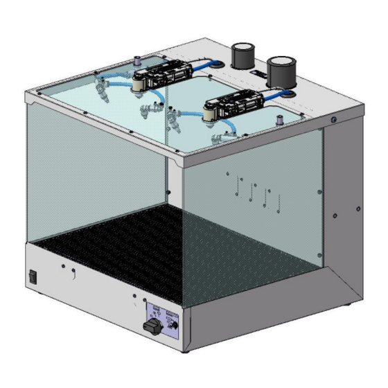
Dust collecting 3 m exhaust duct hose Dust collecting bag Appearance of the product with the options mounted 2.3 Construction Component parts Description Remarks Description Remarks Additional air flow pulse Ionizer With diffusion nozzle Pulse selection operation time set switch Additional air flow nozzle Nozzle diameter ø1.0 Cover for valve maintenance... -
Page 13: Dimensions
2.4 Dimensions - Desktop duster box body (product No.:ZVB40-B**-*) - Exhaust dust hoses set (part No.: ZVB-D3A) (*) Connection inside diameter: ø32mm, outside diameter: ø36mm Hose band (Material: SUS) Exhaust duct hose (Material: PVC) - Duct collector bag set (Part No.: ZVB-P1A) (*) Connection inside diameter Duct collector bag filtration rating 10μm olyester... -
Page 14: Offset Voltage And Discharge Time
2.5 Offset Voltage and Discharge Time イオナイザ Ionizer ① ② ③ ④ ⑤ ⑥ Actual measurement values of the static elimination performance at the points 1 to 6 are shown below. (See Notes shown below) - Continuous operation of the additional air flow - Pulse operation of the additional air flow(50ms) Point for Point for... -
Page 15: Ionizer Functions
3. Ionizer Functions 3.1 Functions Name and description of indication LEDs PWR ION / HV NDL Symbol Color Description Contents LED is ON when the power supply is ON; LED flashes when Green Power supply indicator the power supply or CPU is abnormal. Green LED is ON: discharge in progress Ion discharge / Green/Red... -
Page 16: Maintenance
4. Maintenance 1. Perform maintenance regularly and clean the emitters. (every 2 weeks suggested.). The maintenance must be performed by an operator who has sufficient knowledge and experience. If the ionizer is used for a long time and there is dust on the electrodes, performance of the product will be reduced. -
Page 17: Valve Maintenance
4.2 Valve Maintenance 1. Rotate the decorative bolt which holds the valve maintenance cover in the counter-clockwise direction by hand to remove the cover. Decorative bolt Cover for valve maintenance 2. Layout of the valves and the piping are shown below. ø... - Page 18 Revision history Edition B Ionizer changed. Replacement parts added. 4-14-1, Sotokanda, Chiyoda-ku, Tokyo 101-0021 JAPAN Tel: + 81 3 5207 8249 Fax: +81 3 5298 5362 URL https://www.smcworld.com Note: Specifications are subject to change without prior notice and any obligation on the part of the manufacturer. ©...
Need help?
Do you have a question about the ZVB Series and is the answer not in the manual?
Questions and answers