Table of Contents
Advertisement
Quick Links
Doc. no. DOC1069701
PRODUCT NAME
Electric Vacuum Gripper
MODEL / Series / Product Number
ZXPE5
011P-
-
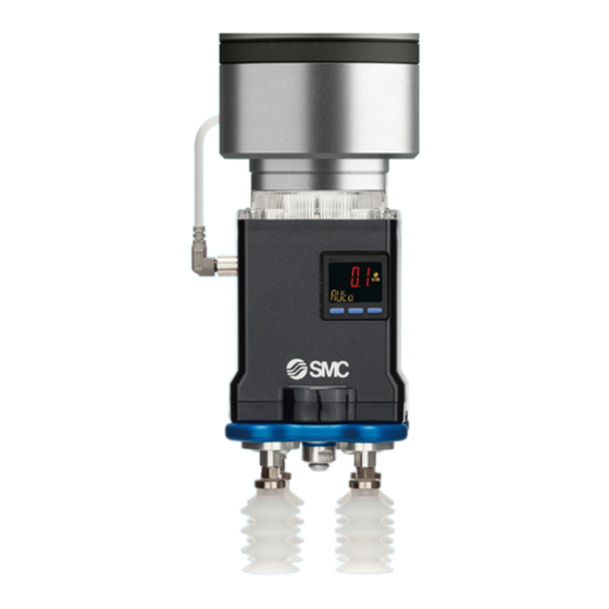
The outward appearance showed on this manual is an example of the vacuum gripper with suction
cups which is indicated by the product number: ZXPE5A011P-25JS-. Refer to the suction cup
catalog for the detail of other applicable suction cups.
Advertisement
Table of Contents

Related Manuals for SMC Networks ZXPE5 011P Series


Summary of Contents for SMC Networks ZXPE5 011P Series
- Page 1 Doc. no. DOC1069701 PRODUCT NAME Electric Vacuum Gripper MODEL / Series / Product Number ZXPE5 011P- The outward appearance showed on this manual is an example of the vacuum gripper with suction cups which is indicated by the product number: ZXPE5A011P-25JS-. Refer to the suction cup catalog for the detail of other applicable suction cups.
-
Page 2: Table Of Contents
Contents Safety instructions…………………………………………………………………………………………………..2 1. Parts included in the package ....................... 6 2. How to order ............................8 3. Names and descriptions of parts ......................10 3.1. Names of parts of the product ....................10 3.2. Descriptions of parts ......................... 11 4. -
Page 3: Safety Instructions
Safety Instructions These safety instructions are intended to prevent hazardous situations and/or equipment damage. These instructions indicate the level of potential hazard with the labels of “Caution,” “Warning” or “Danger.” They are all important notes for safety and must be followed in addition to International Standards (ISO/IEC) , and other safety regulations. - Page 4 Safety Instructions Caution We develop, design, and manufacture our products to be used for automatic control equipment, and provide them for peaceful use in manufacturing industries. Use in non-manufacturing industries is not covered. Products we manufacture and sell cannot be used for the purpose of transactions or certification specified in the Measurement Act.
- Page 5 ■Explanation of Symbols Sy mb o l Definition Things you must not do. Instructions are provided as a drawing or sentence next to the symbol. Things you must do Instructions are provided as a drawing or sentence next to the symbol. ■Operator 1.
- Page 6 Caution Do not touch the terminals and connectors while the power is on. Otherwise electric shock, malfunction or damage to the switch can result. Do not touch Perform sufficient trial run. Otherwise, injury or damage to the system can result due to suction failure depending on the conditions of the suction of the workpiece.
-
Page 7: Parts Included In The Package
1. Parts included in the package Electric Vacuum Gripper: 1 pc. Main plate assembly Part No. RMTM2-4M1 Connector cable: 1 pc. Parallel pin (6x10) × 1, Parallel pin (6x15) × 1, Part No. RMH-A00-11-A Hexagon thin socket head bolt (M6 x 10) × 4, Hexagon (When “With connector cable”... - Page 8 No. DOC1069701...
-
Page 9: How To Order
2. How to order Suction cup part 1 Refer to “ Suction Cup Part Numbers and Weights” for the applicable cups. ■ - 20 - ZXPE Electric Vacuum Gripper 2. Robot manufacturer 3. Output type 5. Cup form 4. Cup diameter 1. - Page 10 ■Suction Cup Part Numbers and Weights ZXPE5(A,N)011P Applicable cups Cup part numbers Adapter unit Cup unit Cup with adapter Vacuum inlet: Male thread M6×1 Weight by cup material(g/cup) diameter form material attach- Part No. S/SF ment (NBR) (FKM) (Silicone rubber) (Urethane rubber) ZPT08U*-A6 ZP08U* ZPT08B*-A6...
-
Page 11: Names And Descriptions Of Parts
3. Names and descriptions of parts 3.1. Names of parts of the product Main plate assembly Parallel pin Main plate Switch cover DIP switch When the Lamp cover cover is removed Pressure monitor Vacuum pump SET/TEST button Atmospheric release valve Vacuum port Cup mounting flange assembly O-ring... -
Page 12: Descriptions Of Parts
3.2. Descriptions of parts Main plate assembly: Connects the gripper with the robot. LED: Indicates the gripper status. DIP switch: Changes the gripper operation mode. Pressure monitor: Displays real-time vacuum pressure, the gripper operation mode and sets parameter threshold values. Vacuum pump: Generates vacuum. - Page 13 3.2.2. DIP switch (for changing the gripper operation mode) To change the gripper operation mode, use the 2-pole DIP switch on the top of the product. Change the operation mode before mounting the electric vacuum gripper on the robot, while the power is off. How to change 1.
- Page 14 3.2.3. Gripper operation modes 3.2.3.1. Automatic mode In automatic mode, the electric vacuum gripper operates in an energy-saving manner, automatically setting a threshold value based on the vacuum pressure at gripping, the maximum vacuum pressure of the product, and the pre-determined vacuum pressure without workpiece (*). Below is the description of the energy-saving operation.
- Page 15 3.2.3.2. Manual mode In manual mode, threshold values are manually set, and the vacuum gripper operates in an energy-saving manner (which controls the pump’s actions) similarly to automatic mode. The following four threshold values can be set as described in “5.2.2.3.
- Page 16 3.2.4. Pressure monitor display Operation light (OUT1) Main display Indicator light ( ) IO-Link status indicator light Operation light (OUT2) Sub display (left) Sub display (right) button button button Main display: Displays pressure measurement values. (in red) Sub display (left): Displays the current gripper operation mode or parameter (in orange) Sub display (right): Displays the set value, peak value or bottom value (in orange) The buttons on the pressure monitor are used only in manual mode or to change the measurement unit.
-
Page 17: Mounting
4. Mounting 4.1. Mounting ■Mounting the gripper on the robot 1) Insert the parallel pin into the robot tool flange pin hole. 2) Aligning the parallel pin with the oval hole of the main plate, mount the main plate on the robot with 4 hexagon thin socket head bolts provided, with a tightening torque of 5.2±0.5 N·m. - Page 18 Caution Mount the electric vacuum gripper on the robot in an orientation that minimizes slack in the M8 connector cable. If the cable slack is large, the cable may cause an unexpected accident by pulling on the surrounding equipment, workpieces, or people while the robot is in operation. <Example of mounting>...
-
Page 19: Wiring
4.2. Wiring ■Mounting the M8 connector cable Connect the electric vacuum gripper’s M8 connector pin and the tool flange’s tool I/O connector together with the M8 connector cable. Do not energize while securing the connector. Check that the connector is not loose. M8 connector cable Tool I/O connector Tool flange... -
Page 20: Power On
4.3. Power on When supply voltage is applied to the M8 connector cable, the pressure monitor is turned on and performs zero-clear (*). The LED flashes green, indicating that the electric vacuum gripper is idling. Caution Power on the electric vacuum gripper with the vacuum port released to atmosphere. This product clears the display value to zero upon power on. -
Page 21: Operation
5. Operation 5.1. Initial setup and diagnostic function The following initial setup and diagnostic can be performed. Table 4. Initial setup and diagnostic items Vacuum port Pressure monitor sub Setup and diagnostic item Function Execution timing Note 1 status screen display Note 2 Vacuum pressure without Atmospheric... - Page 22 2. Double click to change the display on the left of the sub screen. Initial setup – Diagnostic – Diagnostic – Vacuum pressure Gripper maximum Vacuum pressure without workpiece Pe vacuum pressure Pp without workpiece Pe 3. With the item to be measured or diagnosed displayed, press for one or more seconds and less than three seconds to operate the pump for five seconds and measure the pressure.
- Page 23 Table 5. Initial setup and diagnostic results display and diagnostic details Display of setup and Function Setup and diagnostic item Contents of diagnostic Countermeasure diagnostic results ・Pressure monitor Vacuum pressure without Initial setup workpiece: Pe Left: Setup mesurement value, Right: No display ・LED Note 1 If setup is completed: Green light...
-
Page 24: Using Urcap
5.2. Using URCap Each setting is basically made on the URCap, but only the initial setup is made using SET/TEST button. The instruction flowchart is shown below. Installation of URCap Refer to 5.2.1 for how to install the software. Others Basic settings ・Initial setup: Set the following:... - Page 25 5.2.1. Installation of URCap The URCap is plugin software for the UR robot e series. It uses RS485 communication. Checking the UR robot version The plugin software is compatible with a UR robot Polyscope version 5.9.1 or later. Before installing the plugin software, update the Polyscope to the 5.9.1 or later version, if it is prior to 5.9.1.
- Page 26 3. Select “SMC-ElectricVacuumGripperSI-x.x.x.urcap” from ”Files” and tap the "Open" button. 4. Tap the "Restart" button to restart the robot. Caution URCap which is installed on "Active URCaps" must be "SMC Electric Vauum Gripper SI units only" only and uninstall any other URCaps. It causes communication failure, and it may not go online when more than one URCaps are installed.
- Page 27 5.2.2. Basic settings 5.2.2.1. Tool I/O After restarting the robot, press “Installation” to open ‘Tool I/O’ from “General’. Then, select “SMC Electric Vacuum Gripper SI units only” from the “Controlled by” drop down list. “Analog Inputs – Communication Interface” and “Digital Output Mode” will be set automatically. -26- No.
- Page 28 5.2.2.2. General Settings Open “General Settings” from the “URCaps” menu in the “Installation” tab. 1. Select the display pressure unit: allows the user to change the measurement unit and set the pressure unit displayed on the URCap as well as the pressure unit displayed on the gripper’s pressure monitor. Selecting the pressure unit in the pull-down menu and tapping “APPLY”...
- Page 29 4. Factory reset: Allows the user to reset the gripper to the factory settings if the current settings are uncertain. Tapping “APPLY” opens a window asking whether “Factory reset” is to perform. When “OK” is selected, the settings of the gripper and on the URCap will be reset to default. For the default values, refer to “6.2.
- Page 30 5.2.2.3. Pump Settings Open “Pump Settings” from the “URCaps” menu in the “Installation” tab. 1. Default mode: Allows the user to change the default gripper operation mode on the program and commissioning windows. Refer to “3.2.2. DIP switch (for changing the gripper operation mode)”...
- Page 31 5.2.3. Command settings This product has two program commands: “GRIP” and “RELEASE”. GRIP From the “URCaps” menu in the “Program” tab, tap “SMC Electric Vacuum Gripper. Select “Grip” in “Select operation” to add “Grip: SMC Electric Vacuum Gripper” command to the “Robot Program”. Settings: Allows the user to set the parameters for each command.
- Page 32 RELEASE From the “URCaps” menu, tap “SMC Electric Vacuum Gripper”. Select “RELEASE” in “Select operation” to add the “Release: SMC Electric Vacuum Gripper” command to the “Robot Program”. Settings: Allows the user to set the parameters for each command. Atmospheric release time: Sets the duration of time for a valve to release air to atmosphere. The time can be set between 200 to 5000 msec.
- Page 33 5.2.4. Illustration of the gripper status while the program is running 5.2.4.1. Pressure monitor display After the electric vacuum gripper is energized, the sub screen (left) of the pressure monitor shows the gripper operation mode set by the DIP switch. While the program is running, the gripper operation mode set by each GRIP command is displayed.
- Page 34 5.2.4.3. Electric vacuum gripper status and output signals While the program is running, a signal according to the status of the gripper (success, failed or occurrence of an alarm) is sent, and the program continues or stops. Table 8. Status signal outputs and program actions Note 2 Program operation Gripper status...
- Page 35 5.2.5. Commissioning The “UR+” icon on the top right of the interface allows the user to commission the gripper. to perform the gripper’s grip or release operation and see status, and vacuum pressure. Note that the status signals set according to “5.2.2.2.
-
Page 36: When Urcap Is Not Used
5.3. When URCap is not used If the RS485 communication plugin software is not used, the grip/release commands are entered by a digital input signal, and the gripper’s status is checked by a digital output signal. Use the buttons on the gripper body to set each parameter. - Page 37 5.3.1. IO communication Tool IO signals Digital inputs are allocated to the gripper’s control signals, and digital outputs are allocated to the status signals. Table 10. Digital inputs (control signals from the robot to the gripper) Digital input 0 Digital input 1 Status Idle Grip command...
- Page 38 5.3.2. Illustration of the gripper operation via IO communication Example 1 – Grip/release motion and work drop detection Robot: ON Grip command Workpiece dropped Starts energizing gripper Release command Grip command Robot: OFF Digital input 0:Grip Digital input 1:Release P2-H2 Vacuum pressure value Atmospheric pressure...
- Page 39 Example 2 – Gripping failed Robot: ON Starts energizing gripper Grip command Release command Grip command Digital input 0:Grip Digital input 1:Release P2-H2 Vacuum pressure value Atmospheric pressure No light No light Flashing green No light LED display Red light Green light Flashing green Image of gripper...
- Page 40 5.3.3. Keylock function The set button ( ) on the pressure monitor is locked by default. Unlock the button as shown below before changing threshold values (in manual mode) or changing the measurement unit. After setting is completed, lock the button again or power off and on the electric vacuum gripper to lock the button.
- Page 41 3. Press the button to change the set value. button increases the value, and the button decreases it. Pressing the button once increases (or decreases) the value by one digit, pressing and holding the button increases (or decreases) the value continuously. 4.
- Page 42 5.3.6. Factory reset The gripper can be reset to the factory settings if the current settings are uncertain. For the default values, refer to “6.2. List of setting items”. How to reset 1. Press and hold the button for 10 seconds or longer until [RSET] is shown on the left of the sub screen of the pressure monitor, and then release the button.
-
Page 43: Specifications
6. Specifications 6.1. Specifications ■Product specifications Table12. Specifications Standards Conforming to “ISO 9409-1-50-4-M6” 5 to 40 Operating temperature range [°C] Connector type M8 8-pin connector (Plug) Weight [g] without cups with adapter 722 (556) Gripper Max. workload [kg] Max. vacuum pressure [kPa] Suction flow rate [L/min(ANR)] Impact / Vibration resistance [m/s²] 150 / 30... -
Page 44: List Of Setting Items
6.2. List of setting items Table 13. List of setting items Setting items Factory default Adjustable range Note Dip switch Gripper operation modes Automatic mode Refer to #Table 2. 1 pole: OFF, 2 pole: OFF Display pressure unit Refer to #Table 14. -
Page 45: Dimensions
7. Dimensions 7.1. Electric Vacuum Gripper *1 The cup with adapter ZP2-TB25JS-AS6 is used. *2 Operating range: 25 to 35 (when a cup is mounted in the center). Cups interfere each other depending on the cup diameter. Select the cup diameter according to the pitch to be used. *3 No mesh is fitted to the vacuum port. - Page 46 7.2. Tool center point and center of gravity M8 Connector SET/TEST button Pressure monitor Table 16. ZXPE5A011P-- (When “With flange assembly (42 mm×42 mm)” is selected) Tool center point (T.C.P.) 133.0+Cup Center of gravity (C.O.G.) -1.5 69.5 (Unit: mm) Table 17. ZXPE5N011P-- (When “Without flange assembly” is selected) Tool center point (T.C.P.) 113.0+Cup Center of gravity (C.O.G.)
-
Page 47: Suction Cup With Adapter
7.3. Suction cup with adapter Representative models only are shown. See the suction cup catalog for the other models. Model: ZPTC-AS6 Model:ZPTU-AS6 (Suction cup: Flat type with ribs) (Suction cup: Flat type) Dimensions Model ZPT10U*-AS6 17.5 ZPT13U*-AS6 ZPT16U*-AS6 22.5 ZPT20U*-AS6 19.5 ZPT25U*-AS6 ZPT32U*-AS6... - Page 48 Model: ZP2-T16J-AS6 Model: ZP2-T(B25, B30)J-AS6 (Suction cup: Multistage bellows type 2.5-Stage) (Suction cup: Multistage bellows type 3.5-Stage) Table. Dimensions Model ZP2-TB25J-AS6 26.2 10.2 32.5 52.5 ZP2-TB30J-AS6 32.9 13.8 54.5 -47- No. DOC1069701...
-
Page 49: Technical Information
8. Technical information 8.1. How to calculate theoretical lifting force This manual only shows how to calculate the theoretical lifting force of a cup. Refer to the catalog of suction cups for details on how to select a suction cup. ■How to calculate theoretical lifting force The theoretical lifting force of a cup can be found by calculation or from the theoretical lifting force table. -
Page 50: How To Change The Number Of Cups
8.2. How to change the number of cups 8.2.1. Change to 1 cup (with flange) 1. Removal of the cup (1) Remove the suction cup with adapter from Plate B using a spanner. (2) Loosen the bolt (M4x8) to remove Plate B from Plate A. Be careful not to lose the O-ring. - Page 51 Change to 1 cup (without flange) 8.2.2. Caution No mesh is fitted to the gripper’s vacuum port (V-port). If a mesh is required, use a cup mounting flange. If the flange is not used, take care to prevent foreign objects from entering the vacuum port. 1.
- Page 52 Change to 2 cups 8.2.3. 1. Removal of the cup (1) Remove the suction cup with adapter from the plate B using a spanner. (2) Loosen the bolt (M4x8), then remove plate B from plate A. Be careful not to lose the O-ring. 2.
-
Page 53: Suction With A Vacuum Saving Valve
8.3. Suction with a vacuum saving valve This product connects four suction cups to one vacuum pump. This means that gripping failure of one cup leads to further failures of the other cups. Take safety measures to prevent workpieces from being dropped during transport. If one of the cups may not have a workpiece to grip, the use of the ZP2V series vacuum saving valve (Part number depends on the number of cups. - Page 54 Examples ・Handling a narrow workpiece The vacuum saving valve helps the suction of a narrow workpiece, as s shown in the figure below when gripping with 2 cups. ・Handling more than one workpiece The vacuum saving valve helps to hold workpieces gripped by the gripper one at a time in each cup and to transport them all at the same time.
-
Page 55: Maintenance
9. Maintenance Perform the maintenance and inspection shown below in order to use the electric vacuum gripper in a safe and appropriate manner for a long time. 9.1. Maintenance for electric vacuum gripper Caution 1) Inspection before and after maintenance When removing the product from the robot, ensure that the power supply is turned off and the vacuum pressure inside the product is released. -
Page 56: Maintenance For Suction Cup
9.2. Maintenance for suction cup Caution 1) Suction cups are consumables. Replace them on a regular basis. Continued use of suction cups will cause wear and tear on the gripping surface, and the exterior dimensions will be gradually reduced, which can lead to a reduction in lifting force, whilst gripping will remain possible. It is extremely difficult to predict when a suction cup should be replaced. -
Page 57: Spare Parts
9.3. Spare parts Table 20. Spare part numbers Accessories provided Name Part number Cup mounting flange Cup mounting flange, Plate B, Suction cup connection ZXPE5-PFL1-A assembly adapter, Mounting bolt, Plug, O-ring Plate B, Mounting bolt, O-ring Plate B ZXPE5-APL6-A Extension adapter, Plug, O-ring Suction cup adapter ZXPE5-EXP6 Main plate, Mounting bolt, Clamper, Parallel pin... -
Page 58: Precautions
10. Precautions 10.1. Electric vacuum gripper precautions ■Designing Warning If power or air supply is shutdown, vacuum pressure may decrease and this product may drop a workpiece during gripping. It is necessary to take measures such as drop prevention so that injury and damage to machinery or equipment can be prevented. -
Page 59: Suction Cup Precautions
■Workpiece Caution Do not use the product for workpieces with water or dust attached. If water or dust adheres to the surface of a workpiece, they may enter the inside of the product, causing a decline in vacuum performance. If the workpiece is permeable, the gripper may not generate sufficient lifting force. - Page 60 6) Use caution since the workpiece could rotate during transfer. Use of more than one cup for each workpiece is recommended. Horizontal lifting Vertical lifting (This type of application should generally be avoided.) ■Storage Caution It is recommended to store suction cups in the environment shown in the table below. Storing in an environment other than that recommended below may lead to changes in properties (deformation, discoloration, cracking, increased adhesiveness, etc.).
-
Page 61: Troubleshooting
11.Troubleshooting List of problems and countermeasures Problem Cause Countermeasure Communication Multiple plugin software is There may be interference from plugin software. failure installed. Uninstall any plugin software other than this product. Recheck the relationship between workpiece mass Gripping area is small. and lifting force. - Page 62 Problem Cause Countermeasure Insufficiently short atmospheric Select the piping condition to fit atmospheric release release time time within 0.5 seconds. Replace cups. The increase of stickiness due to Check the compatibility of the cup material and Workpiece is not the wearing of the cup (rubber). workpiece condition.
- Page 63 Alarms When an alarm occurs, the LED will flash red. The description of the alarm is displayed on the URCap. (Refer to 5.2.4.2. URCap display.) Table 21. List of alarms Alarm Product status Message Countermeasure A pressure outside of the upper or lower limit Temporary LED: flashes red Pressure monitor...
- Page 64 Revision history Tel: + 81 3 5207 8249 Fax: +81 3 5298 5362 https://www.smcworld.com Note: Specifications are subject to change without prior notice and any obligation on the part of the manufacturer. © SMC Corporation All Rights Reserved -63- No. DOC1069701...
Need help?
Do you have a question about the ZXPE5 011P Series and is the answer not in the manual?
Questions and answers