Table of Contents
Advertisement
Quick Links
Advertisement
Table of Contents

Related Manuals for AXIOMTEK KIWI310


Summary of Contents for AXIOMTEK KIWI310
- Page 1 KIWI310 ® ® Intel Celeron N3350 Processor 1.8” Board User’s Manual...
- Page 2 Axiomtek does not make any commitment to update the information in this manual. Axiomtek reserves the right to change or revise this document and/or product at any time without notice. No part of this document may be reproduced, stored in a retrieval system, or transmitted, in any form or by any means, electronic, mechanical, photocopying, recording, or otherwise, without the prior written permission of Axiomtek Co., Ltd.
-
Page 3: Esd Precautions
It discharges static electricity from your body. ◼ Wear a wrist-grounding strap, available from most electronic component stores, when handling boards and components. Trademarks Acknowledgments Axiomtek is a trademark of Axiomtek Co., Ltd. ® ® Intel and Celeron are trademarks of Intel Corporation. -
Page 4: Table Of Contents
Table of Contents Disclaimers ..................... ii ESD Precautions ................... iii Section 1 Introduction ..........1 Features ....................1 Specifications ..................2 Utilities ....................3 Section 2 Board and Pin Assignments ....5 Board Dimensions and Fixing Holes ..........5 Board Layout ..................7 Assembly Drawing ................ - Page 5 Navigation Keys ................25 Main Menu ..................27 Advanced Menu ................. 28 Chipset Menu ..................33 Security Menu ..................36 Boot Menu ..................39 Save & Exit Menu ................41 Appendix A Watchdog Timer ........43 About Watchdog Timer ..............43 How to Use Watchdog Timer ............
- Page 6 This page is intentionally left blank.
-
Page 7: Introduction
KIWI310 1.8” Board Section 1 Introduction The KIWI310 is a credit card size board with Intel ® Celeron ® N3350 processor that deliver outstanding system performance through high-bandwidth interfaces, multiple I/O functions for interactive applications and various embedded computing solutions. -
Page 8: Specifications
KIWI310 1.8” Board Specifications ⚫ ® ® ◼ Intel Celeron dual core N3350 processor (1.1GHz). ⚫ Thermal Solution ◼ Fanless heatsink. ⚫ Operating Temperature ◼ 0°C~+60°C ⚫ BIOS ◼ American Megatrends Inc. UEFI (Unified Extensible Firmware Interface) BIOS. ◼ 128Mbit SPI Flash, DMI, Plug and Play. -
Page 9: Utilities
KIWI310 1.8” Board ⚫ Power Input ◼ One USB type C connector. ◼ +9 ~ +20V DC-In @ 3A. ◼ Required PD support power adapter or power bank. ◼ Auto power on function supported. ⚫ Power Management ◼ ACPI (Advanced Configuration and Power Interface). - Page 10 KIWI310 1.8” Board This page is intentionally left blank. Introduction...
-
Page 11: Board And Pin Assignments
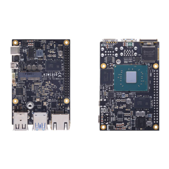
KIWI310 1.8” Board Section 2 Board and Pin Assignments Board Dimensions and Fixing Holes Top View Board and Pin Assignments... - Page 12 KIWI310 1.8” Board Bottom View Board and Pin Assignments...
-
Page 13: Board Layout
KIWI310 1.8” Board Board Layout Top View Side View Board and Pin Assignments... - Page 14 KIWI310 1.8” Board Bottom View Board and Pin Assignments...
-
Page 15: Assembly Drawing
For thermal dissipation, a heatsink enables the KIWI310’s components to dissipate heat efficiently. All heat generating components are thermally conducted to the heatsink in order to avoid hot spots. Images below illustrate how to install the thermal solution on KIWI310. Board and Pin Assignments... -
Page 16: Switch Settings
KIWI310 1.8” Board Switch Settings Properly configure switch setting on the KIWI310 to meet your application purpose. Below you can find a summary table of onboard default settings. Once the default switch setting needs to be changed, please do it under power-off condition. -
Page 17: Connectors
KIWI310 1.8” Board Connectors Signals go to other parts of the system through connectors. Loose or improper connection might cause problems, please make sure all connectors are properly and firmly connected. Here is a summary table of connectors on the hardware. -
Page 18: 40-Pin Gpio Header (Cn1)
KIWI310 1.8” Board 2.5.1 40-pin GPIO Header (CN1) This is a 40-pin (pitch=2.54mm) header. Signal Signal +3.3V level +5V level I2C_SDA/GPIO2 +5V level I2C_SCL/GPIO3 GPIO4 UART_TX/GPIO14 UART_RX/GPIO15 GPIO17 GPIO18 GPIO27 GPIO22 GPIO23 +3.3V level GPIO24 SPI_MOSI/GPIO10 SPI_MISO/GPIO9 GPIO25 SPI_SCK/GPIO11 SPI_CS0/GPIO8... -
Page 19: Ethernet Port (Cn3)
KIWI310 1.8” Board 2.5.3 Ethernet Port (CN3) Connection can be established by plugging one end of the Ethernet cable into the RJ-45 connector and the other end (phone jack) to a 1000/100/10-Base-T hub. 1000 100/10 Description Base-T Base-T BI_DA+ Bidirectional or Transmit Data+... -
Page 20: 2230 Key E Connector (Cn5)
KIWI310 1.8” Board 2.5.5 M.2 2230 Key E Connector (CN5) The CN5 is a M.2 2230 Key E connector. It is suggested to install the M.2 wireless module via PCIe x1 and USB 2.0 with 22mm width and 30mm length. -
Page 21: Usb 2.0 Port (Cn6)
KIWI310 1.8” Board 2.5.6 USB 2.0 Port (CN6) The CN6 is a Universal Serial Bus (compliant with USB 2.0 (480Mbps)) connector on the rear I/O. It is commonly used for installing USB peripherals such as keyboard, mouse, scanner, etc. Signal... -
Page 22: Micro Hdmi Connector (Cn8)
KIWI310 1.8” Board 2.5.8 Micro HDMI Connector (CN8) The micro HDMI is a miniaturized type of the High Definition Multimedia Interface specification designed to transmit high-definition video and high-resolution audio over a single cable. Signal Signal HDMI_HTPLG N.C. HDMI OUT_DATA2+... -
Page 23: Hardware Description
Make sure all correct settings are arranged for your installed microprocessor to prevent the CPU from damages. BIOS The KIWI310 uses AMI Plug and Play BIOS with a single 128Mbit SPI Flash. System Memory The KIWI310 supports onboard LPDDR4 memory with maximum capacity up to 4GB. -
Page 24: I/O Port Address Map
KIWI310 1.8” Board I/O Port Address Map Hardware Description... -
Page 25: Interrupt Controller (Irq) Map
KIWI310 1.8” Board Interrupt Controller (IRQ) Map The interrupt controller (IRQ) mapping list is shown as follows: Hardware Description... - Page 26 KIWI310 1.8” Board Hardware Description...
- Page 27 KIWI310 1.8” Board Hardware Description...
- Page 28 KIWI310 1.8” Board Hardware Description...
- Page 29 KIWI310 1.8” Board Hardware Description...
-
Page 30: Memory Map
KIWI310 1.8” Board Memory Map The memory mapping list is shown as follows: Hardware Description... -
Page 31: Ami Bios Setup Utility
KIWI310 1.8” Board Section 4 AMI BIOS Setup Utility The AMI UEFI BIOS provides users with a built-in setup program to modify basic system configuration. All configured parameters are stored in a flash chip to save the setup information whenever the power is turned off. This section provides users with detailed description about how to set up basic system configuration through the AMI BIOS setup utility. - Page 32 KIWI310 1.8” Board Hot Keys Description → Left/Right The Left and Right <Arrow> keys allow you to select a setup screen. The Up and Down <Arrow> keys allow you to select a setup screen or Up/Down sub-screen. The Plus and Minus <Arrow> keys allow you to change the field value of a +−...
-
Page 33: Main Menu
KIWI310 1.8” Board Main Menu When you first enter the setup utility, you will enter the Main setup screen. You can always return to the Main setup screen by selecting the Main tab. System Time/Date can be set up as described below. -
Page 34: Advanced Menu
KIWI310 1.8” Board Advanced Menu The Advanced menu also allows users to set configuration of the CPU and other system devices. You can select any of the items in the left frame of the screen to go to the sub menus: ►... - Page 35 KIWI310 1.8” Board ⚫ Hardware Monitor This screen monitors hardware health status. This screen displays the temperature of system and CPU, system voltages (+VBAT and +5V). ⚫ SDIO Configuration You can use this screen to select options for the SDIO (Secure Digital Input/Output) configuration.
- Page 36 KIWI310 1.8” Board ⚫ ACPI Settings You can use this screen to select options for the ACPI configuration, and change the value of the selected option. A description of the selected item appears on the right side of the screen.
- Page 37 KIWI310 1.8” Board ⚫ CPU Configuration This screen shows the CPU Configuration and you can change the value of the selected option. Intel Virtualization Technology Enable or disable Intel ® Virtualization Technology. When enabled, a VMM (Virtual Machine Mode) can utilize the additional hardware capabilities. It allows a platform to run multiple operating systems and applications independently, hence enabling a computer system to work as several virtual systems.
- Page 38 KIWI310 1.8” Board ⚫ USB Configuration USB Devices Display all detected USB devices. AMI BIOS Setup Utility...
-
Page 39: Chipset Menu
KIWI310 1.8” Board Chipset Menu The Chipset menu allows users to change the advanced chipset settings. You can select any of the items in the left frame of the screen to go to the sub menus: ► North Bridge ►... - Page 40 KIWI310 1.8” Board ⚫ North Bridge Memory Information Display system memory information. AMI BIOS Setup Utility...
- Page 41 KIWI310 1.8” Board ⚫ South Bridge ® This screen shows Intel MRC/PMC/TXE FW version. Wake on LAN Enable or disable integrated LAN to wake the system. AMI BIOS Setup Utility...
-
Page 42: Security Menu
KIWI310 1.8” Board Security Menu The Security menu allows users to change the security settings for the system. ⚫ Setup Administrator Password Set setup administrator password. ⚫ User Password Set user password. ⚫ Secure Boot Use this item to set parameters related to Secure Boot. - Page 43 KIWI310 1.8” Board ⚫ Secure Boot The Secure Boot feature is designed to ensure and protect the system from unauthorized access and malwares during boot-up. Secure Boot Secure Boot activated when Platform Key (PK) is enrolled, system mode is user/deployed and CSM is disabled.
- Page 44 KIWI310 1.8” Board ⚫ Key Management Factory Key Provision Enable or disable provision factory default keys on next reboot only when System in Setup mode. Restore Factory Keys Force System to User mode. Install factory default Secure Boot key databases.
-
Page 45: Boot Menu
KIWI310 1.8” Board Boot Menu The Boot menu allows users to change boot options of the system. ⚫ Setup Prompt Timeout Number of seconds to wait for setup activation key. 65535(0xFFFF) means indefinite waiting. ⚫ Bootup Numlock State Use this item to select the power-on state for the keyboard NumLock. - Page 46 KIWI310 1.8” Board ⚫ Boot Mode Use this item for boot mode settings. UEFI Mode: Select support to boot any UEFI-capable OS. Legacy Mode: Select support to boot non UEFI-capable OS that expects a legacy BIOS interface. ⚫ Boot Option Priorities These are settings for boot priority.
-
Page 47: Save & Exit Menu
KIWI310 1.8” Board Save & Exit Menu The Save & Exit menu allows users to load your system configuration with optimal or fail-safe default values. ⚫ Save Changes and Exit When you have completed the system configuration changes, select this option to leave Setup and return to Main Menu. - Page 48 KIWI310 1.8” Board ⚫ Discard Changes Select this option to quit Setup without making any permanent changes to the system configuration. Select Discard Changes from the Save & Exit menu and press <Enter>. Select Yes to discard changes. ⚫ Restore Defaults It automatically sets all Setup options to a complete set of default settings when you select this option.
-
Page 49: Appendix A Watchdog Timer
KIWI310 1.8” Board Appendix A Watchdog Timer A.1 About Watchdog Timer Software stability is major issue in most application. Some embedded systems are not watched by operator for 24 hours. It is usually too slow to wait for someone to reboot when computer hangs. -
Page 50: A.3 Sample Program
KIWI310 1.8” Board A.3 Sample Program Assembly sample code : ;Enable WDT: dx,2Eh al,87 ;Un-lock super I/O dx,al dx,al ;Select Logic device: dx,2Eh al,07h dx,al dx,2Fh al,07h dx,al ;Enable WDT base address: dx,2Eh al,30h dx,al dx,2Fh al,01h dx,al ;Activate WDT:... - Page 51 KIWI310 1.8” Board If N=F9h, the time base is set to minute. M = time value 00: Time-out disable 01: Time-out occurs after 1 minute 02: Time-out occurs after 2 minutes 03: Time-out occurs after 3 minutes FFh: Time-out occurs after 255 minutes...
Need help?
Do you have a question about the KIWI310 and is the answer not in the manual?
Questions and answers