
Subscribe to Our Youtube Channel
Related Manuals for Haulotte Group OPTIMUM 8


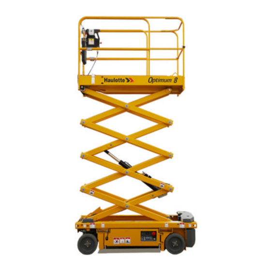
Summary of Contents for Haulotte Group OPTIMUM 8
- Page 1 Maintenance Book Maintenance Book OPTIMUM 8 - OPTIMUM 1931 E 4000429690 E 11.15 US / GB...
- Page 2 OPTIMUM 8 - OPTIMUM 1931 E 4000429690 E 11.15 US / GB...
-
Page 3: Table Of Contents
Maintenance Book CONTENTS Preface - Foreword 1 - Symbols and colors ..... . Safety 1 - General safety rules ..... 1.1 - Maintenance implementation. - Page 4 Maintenance Book Familiarizatio 1 - Primary machine components ... . 1.1 - Layout............1.2 - Maintenance support .
- Page 5 Maintenance Book Inspection maintenance schedule 1 - Maintenance Schedule ....2 - Inspection program ..... 3 - Daily inspection .
- Page 6 Maintenance Book Trouble shooting and diagram 1 - Trouble shooting ..... . 1.1 - Recommendations......... . . 1.2 - Description .
-
Page 7: Preface - Foreword
OPTIMUM 8 - OPTIMUM 1931 E Preface - Foreword You have just purchased a HAULOTTE® product and we would like to thank you for your business. The Aerial Work Platform is a mechanical device primarily designed and manufactured with the intent to position people with the necessary tools and material to overhead elevated temporary workplaces. -
Page 8: Symbols And Colors
OPTIMUM 8 - OPTIMUM 1931 E - Preface - Foreword 1 - Symbols and colors Symbols and colors are used to alert the operator of safety precautions and/or to highlight important safety information. The following safety symbols are used throughout this manual to indicate specific hazards and the hazard severity level when operating or maintaining the Aerial Work Platform. - Page 9 OPTIMUM 8 - OPTIMUM 1931 E - Preface - Foreword D e c a l s Color Title Description Danger : Indicates a hazardous situation which if not avoided, WILL result in death or serious injury. Warning : Indicates a hazardous situation which if not avoided, COULD result in death or serious injury.
- Page 10 OPTIMUM 8 - OPTIMUM 1931 E - Preface - Foreword Notes 4000429690 E 11.15 US / GB...
-
Page 11: Safety
OPTIMUM 8 - OPTIMUM 1931 E - Safety Safety 1 - General safety rules 1.1 - AINTENANCE IMPLEMENTATION Your safety and the safety of the people around are essential. Make sure the work area is clean in order to not to pollute the system of the machine. -
Page 12: Uncontrolled Movement Hazard
OPTIMUM 8 - OPTIMUM 1931 E - Safety Note : • Using the machine during maintenance is strictly forbidden. • Do not climb onto the covers. • The handling of parts must be carried out using appropriate equipment (Chains, Lifting slings, Lifting anchors). -
Page 13: Electrocution Hazards
OPTIMUM 8 - OPTIMUM 1931 E - Safety 1.3 - LECTROCUTION AZARDS The machine is not electrically insulated and does not provide protection from contact or proximity to electrically charged conductors. Always position the lift at a safe distance from electrically charged conductors to ensure that no part of the machine is within an unsafe area. -
Page 14: Explosion / Fire Hazards
OPTIMUM 8 - OPTIMUM 1931 E - Safety 1.4 - XPLOSION AZARDS Always wear protective clothing and eye wear when working with batteries and power sources/systems. N.B.-:-A CID IS NEUTRALIZED WITH SODIUM BICARBONATE AND WATER • Do not start the engine if you smell or detect liquid propane gas (LPG), gasoline, diesel fuel or other explosive substances. -
Page 15: Maintenance And Repair Training
HAULOTTE S ® ERVICES The HAULOTTE Group is at your service in all 5 continents of the world via an extensive network of its own factory trained technicians, who are ready to respond to your every need. 2.4 - RAINING Whether you want to just service your equipment or carry out a complete overhaul, HAULOTTE®... -
Page 16: Product Modification
Any modification may violate Haulotte design parameters, government regulations and industry standards. If you desire a modification to the product, submit a request in writing to HAULOTTE Group. With the utmost care to ensure enhanced reliability and greater safety of the HAULOTTE® products, it is pertinent that when a "Service or Safety Bulletin"... -
Page 17: Manufacturer's Warranty
OPTIMUM 8 - OPTIMUM 1931 E - Safety 3 - Manufacturer's warranty 3.1 - ARRANTY ACCEPTANCE On reception of his machine, the owner or rental company must check the machine's condition and fill out the machine reception slip provided. 3.2 -... -
Page 18: Warranty Conditions
OPTIMUM 8 - OPTIMUM 1931 E - Safety • Hydraulic and fuel circuit contamination : Every possible precaution is taken to ensure that fuel and hydraulic liquid delivered is clean. On the other hand, in certain cases it is possible to contaminate fuel and hydraulic circuits, especially when fuel and lubricants are stored on the work site. - Page 19 OPTIMUM 8 - OPTIMUM 1931 E - Familiarization Familiarization Notes 4000429690 E 11.15 US / GB...
-
Page 20: Primary Machine Components
OPTIMUM 8 - OPTIMUM 1931 E - Familiarization 1 - Primary machine components 1.1 - AYOUT O P T I M U M O P T I M U M 1 9 3 1 C142 C171 C168 C20 C2 C78 C58... -
Page 21: Maintenance Support
OPTIMUM 8 - OPTIMUM 1931 E - Familiarization Marking Description Marking Description Chassis Platform access ladder Front drive wheels Compartment locking latch Platform Sliding guardrail Platform control box Deck extension handle Tie-down (and/or forklift loading) Scissors Ground control box Battery bay (block) -
Page 22: Ground Control Box
OPTIMUM 8 - OPTIMUM 1931 E - Familiarization 1.3 - ROUND CONTROL BOX 1.3.1 - Layout G e n e r a l v i e w ACTIV’ Screen C o n t r o l s a n d... -
Page 23: Haulotte Activ'screen
OPTIMUM 8 - OPTIMUM 1931 E - Familiarization 1.3.2 - HAULOTTE Activ'Screen Upon starting and during operation of the machine, the LCD screen "Activ'Screen" located on the ground control box displays in real time the machine operating status. H A U L O T T E... -
Page 24: Lcd Screen
OPTIMUM 8 - OPTIMUM 1931 E - Familiarization 1.3.2.1 - LCD screen At startup with the ground or platform controls selected; system initiates a self check : • Bar gets filled up. • Home screen comes on with status icon of the machine - okay to proceed functioning the controls. - Page 25 OPTIMUM 8 - OPTIMUM 1931 E - Familiarization • After pressing on Symbol Description Software part number Software version + Screen software version + Screen version Screen identification + Screen software version Machine serial number displayed • After again pressing on •...
- Page 26 OPTIMUM 8 - OPTIMUM 1931 E - Familiarization Alarm status Alarm status displayed as applicable - samples shown below • Tilt • Overload • Low battery 4000429690 E 11.15 US / GB...
- Page 27 OPTIMUM 8 - OPTIMUM 1931 E - Familiarization Present fault Platform control box E-stop button 4000429690 E 11.15 US / GB...
-
Page 28: Platform Control Box
OPTIMUM 8 - OPTIMUM 1931 E - Familiarization 1.4 - LATFORM CONTROL BOX 1.4.1 - Layout G e n e r a l v i e w 4000429690 E 11.15 US / GB... - Page 29 OPTIMUM 8 - OPTIMUM 1931 E - Familiarization C o n t r o l s a n d i n d i c a t o r s Marking Description Function Tilt indicator Machine on excessive slope Overload indicator...
-
Page 30: Device Layout
OPTIMUM 8 - OPTIMUM 1931 E - Familiarization 2 - Device layout 2.1 - ENSORS AND ACTUATORS S e n s o r s a n d a c t u a t o r s 4000429690 E 11.15 US / GB... -
Page 31: Consumables
OPTIMUM 8 - OPTIMUM 1931 E - Familiarization Description Name Pressure sensor SP400 Pothole limit sensor SQ144 Pothole limit sensor SQ145 Tilt sensor SQ800 Steering potentiometer SR150 Tilt sensor low position SR420 Pothole limit sensor SR722 6 tracks / 23 position for potholes or steering switch (priority for potholes) -
Page 32: Ingredient
OPTIMUM 8 - OPTIMUM 1931 E - Familiarization 4 - Ingredient Ingredient HAULOTTE® code Hydraulic oil 2420801310 Hydraulic oil (Winter option) 2505002640 Biological hydraulic oil 2820304310 4.1 - YDRAULIC OIL Hydraulic oils must comply with the following requirements : • Oil filterability must be compatible with absolute filters •... -
Page 33: Lubrication Diagram
OPTIMUM 8 - OPTIMUM 1931 E - Familiarization 5 - Lubrication diagram L i s t i n g r e d i e n t s Ingredient Symbol HAULOTTE® code Extreme-pressure lithium grease 2820304320 5.1 - REASING POINTS LOCALIZATION •... -
Page 34: Machine Specifications
OPTIMUM 8 - OPTIMUM 1931 E - Familiarization 6 - Machine specifications 6.1 - OVEMENT SPEED To allow checking operation, refer to the following table about originally time per movement. If the values measured by test are not equal to the following : •... -
Page 35: Maintenance Schedule
OPTIMUM 8 - OPTIMUM 1931 E - Inspection and maintenance schedule Inspection and maintenance schedule 1 - Maintenance Schedule The Aerial Work Platform was given an arbitrary Design Life of 10 years at the design stage of the product. There are a number of factors which can affect the design life including but not limited to, severity of operating conditions/routine maintenance which should be carried out in accordance with this manual. - Page 36 OPTIMUM 8 - OPTIMUM 1931 E - Inspection and maintenance schedule Hydraulic oil Hydraulic oil filter Adjusting the hydraulic pressure Scissors Screw ring 4000429690 E 11.15 US / GB...
-
Page 37: Inspection Program
OPTIMUM 8 - OPTIMUM 1931 E - Inspection and maintenance schedule 2 - Inspection program The machine must be inspected on a regular basis at intervals in accordance with the requirements set forth in the Country of use but no less than once a year. The purpose of the inspection is to detect any defect which could lead to an accident during routine use of the machine. -
Page 38: Daily Inspection
OPTIMUM 8 - OPTIMUM 1931 E - Inspection and maintenance schedule 3 - Daily inspection The content and method of inspection must be conducted by operators before using the machine, it includes a visual inspection and functional and security systems testing of the machine. - Page 39 OPTIMUM 8 - OPTIMUM 1931 E - Inspection and maintenance schedule Daily inspection Visual inspection without disassembly Levelling To check by test Corrected applicable Manuals and displays. Clean or replace if necessary. Presence, cleanliness and legibility of the manufacturer's plate...
- Page 40 OPTIMUM 8 - OPTIMUM 1931 E - Inspection and maintenance schedule No cracks, broken weld, paint chipped No visible damage No screws missing / loose parts No foreign items in joints or slides Presence of securely fitted maintenance devices (safety stand) All compartments covers open and lock properly Frame, axle, steering system, stabilizers arms ...
- Page 41 OPTIMUM 8 - OPTIMUM 1931 E - Inspection and maintenance schedule The circuit breaker is working correctly Slope limiting device operates properly Axle locking device operate properly Pothole safety device operate properly (if equipped) Test of load sensing system (visual warning at control box)
-
Page 42: Periodic Inspection
OPTIMUM 8 - OPTIMUM 1931 E - Inspection and maintenance schedule 4 - Periodic inspection The Periodic inspection is a thorough inspection of the operation and safety features of the machine. This should happen before the sale/resale of the machine and at a frequency of 125 hours or 1 year according to the regulations. - Page 43 OPTIMUM 8 - OPTIMUM 1931 E - Inspection and maintenance schedule Periodic inspection In addition to the daily inspection program Visual inspection without disassembly To check by test Visual inspection with small disassembly or movement needed to Levelling reach the part. Replacement is necessary.
- Page 44 OPTIMUM 8 - OPTIMUM 1931 E - Inspection and maintenance schedule No loose screw (Tightening of screws : 1 per year) Presence and fastening of external wire guide Anchor points for handling fixed, undamaged and signalized (if equipped) No foreign body in joints or slides No abnormal gap in joints and slides Frame, axle, steering system, stabilizers arms ...
- Page 45 OPTIMUM 8 - OPTIMUM 1931 E - Inspection and maintenance schedule No screw or missing / loose parts No leaks (battery acid, etc.) Presence and good condition of the batteries: terminations and clamps, electrolyte level ... Presence and state of hydraulic hose...
-
Page 46: Reinforced Inspection
OPTIMUM 8 - OPTIMUM 1931 E - Inspection and maintenance schedule 5 - Reinforced inspection Reinforced periodic inspection is a thorough inspection of the machine structure and to ensure proper functionality. It must be performed every 1500 h or every 3 years, whichever occurs first. - Page 47 OPTIMUM 8 - OPTIMUM 1931 E - Inspection and maintenance schedule Reinforced inspection In addition to the daily inspection program Visual inspection with small disassembly or movement needed to reach the part. Replacement is necessary. Proof tests. Need HAULOTTE Services® authorization. For countries where machines are not subject to controlled periodic maintenance.
-
Page 48: Major Inspection
OPTIMUM 8 - OPTIMUM 1931 E - Inspection and maintenance schedule 6 - Major inspection Major inspection is to ensure the continued safe use of the aerial work platform past the designed life of the machine and for predicted use until the next recommended major inspection. It must be performed every 5000 h or every 5 years, whichever occurs first, and subsequently every 5 years thereafter. - Page 49 OPTIMUM 8 - OPTIMUM 1931 E - Inspection and maintenance schedule Major inspection In addition with daily, periodic, and reinforced inspections Visual inspection with small disassembly or movement Systematic replacement needed to reach the part. Replacement is necessary. Proof tests. Need HAULOTTE Services® authorization. For countries where machines are not subject to controlled periodic maintenance.
- Page 50 OPTIMUM 8 - OPTIMUM 1931 E - Inspection and maintenance schedule Notes 4000429690 E 11.15 US / GB...
-
Page 51: Structural Part Inspection
General data Structural part inspection MS0001 General data Structural part inspection 1 - You will need • Standard tool kit • Protective goggles • Place barriers around the perimeter of the work area • Gloves Exclusively use tools and auxiliary average adapted. Always wear necessary safety clothing. For safety reasons, imperatively respect the following stages during the tests : •... - Page 52 General data Structural part inspection MS0001 3.2 - AJOR INSPECTION A thorough inspection of the structural parts must be realized all the 5000 h or 10 years with disassembling of the element to check the entirety of the welding. All structural part listed Section Familiarization must be disassembled and all weldsmust be review using non-destructive checks.
- Page 53 General data Structural part inspection MS0001 3.3 - UNCTIONAL TESTS The following tests must be carried out each 250 h or 6 months or afterwards : • An important technical intervention. • An accident resulting from a failure of a major component. The following tests must be realized by a qualified staff under secure conditions.
- Page 54 General data Structural part inspection MS0001 Notes 4000429690 E 11.15 US / GB...
-
Page 55: Pins And Bearing Inspection
General data Pins and bearing inspection MS0002 General data Pins and bearing inspection 1 - You will need • Standard tool kit • Protective goggles • Place barriers around the perimeter of the work area • Gloves Exclusively use tools and auxiliary average adapted. Always wear necessary safety clothing. 2 - Preliminary operation The operations of disassembling if they exist should be carried out only on the installations completely disconnected and must be entrusted only to people having the necessary technical training. - Page 56 General data Pins and bearing inspection MS0002 The periodicity can evolve under the following conditions : • Abnormal noise during movements of the structure. • Prolonged storage of the machine ( 6 months). • Specific storage and use Environment (strong moisture and salinity of the air). 4 - Criteria of replacement The pins, stop pins, bushes and bearing must be replaced as soon as one of the anomalies quoted above is noted.
- Page 57 5.1 - INS AND BUSHES For OPTIMUM 8 - OPTIMUM 1931 E only : Never grease the pins and rings of scissor arms. When reassembling bearings and pins ensure that : • Lightly lubricate the housing into which the bearing is to be installed.
- Page 58 General data Pins and bearing inspection MS0002 5.2 - EARINGS For the reassembly of bearings, respect the following stages : • Clean boring and/or the pins to remove all the foreign bodies. • Slightly lubricate boring and/or pins. • Lubricate the ring of the bearing slightly. •...
-
Page 59: Cylinder Inspection
General data Cylinder inspection MS0003 General data Cylinder inspection 1 - You will need • Standard tool kit • Protective goggles • Place barriers around the perimeter of the work area • Gloves Exclusively use tools and auxiliary average adapted. Always wear necessary safety clothing. For safety reasons, imperatively respect the following stages during the tests : •... - Page 60 General data Cylinder inspection MS0003 3.2 - UNCTIONAL TESTS To guarantee an optimal level of performance and safety, functional tests must be realized all the 250 hours or 6 months. The periodicity can evolve under the following conditions : • Anomaly noted during visual inspection. •...
- Page 61 General data Cylinder inspection MS0003 • If the creep of the cylinder rod is higher than the values indicated in the table below, replace the cylinder. Type of cylinders Maximum drift authorised due to an internal leak of the cylinder Lift cylinder arm or boom (Machine After 10 mn, creep <...
- Page 62 General data Cylinder inspection MS0003 3.3 - AJOR INSPECTION A thorough inspection of the structural parts must be realized all the 5000 h or 10 years with disassembling of the element to check the entirety of the welding. Each Cylinder must be disassembled and must be review using non-destructive checks.
-
Page 63: Breaking Test Procedure
General data Breaking test procedure MS0004 General data Breaking test procedure 1 - You will need • Standard tool kit • Protective goggles • Place barriers around the perimeter of the work area • Gloves Exclusively use tools and auxiliary average adapted. Always wear necessary safety clothing. For safety reasons, imperatively respect the following stages during the tests : •... - Page 64 General data Breaking test procedure MS0004 Notes 4000429690 E 11.15 US / GB...
-
Page 65: Torque Values
General data Torque Values MS0005 General data Torque Values 1 - Metric torque chart For screws HAULOTTE®, use columns ( A ), ( B ) and ( C ) : • Screw ( 1 ) grey dull dry, use colums ( A ) •... - Page 66 General data Torque Values MS0005 Metric fastener torque chart This charts is to be used as a guide only unless noted elsewhere in this manual Class 4.6 Class 8.8 Class 12.9 Yell Yell Yellow dry Dull dry (A) Lubed (B) Dull dry (A) Lubed (B) Dull dry (A)
- Page 67 General data Torque Values MS0005 SAE fastener torque chart SAE fastener torque chart This charts is to be used as a guide only unless noted elsewhere in this manual A574 High Grade 5 Grade 8 strength black oxide bolts Size Thread Lubed Lubed...
- Page 68 2223 2190 2969 2670 3620 3560 4826 3000 4067 3 - OPTIMUM 8 - OPTIMUM 1930 E Sub-assemblies Concerned elements Torque Axles Wheels 320 Nm Wheel studs / Driving reducer Loctite 243 - Normal threadlocker Hydraulic motor / Driving reducer...
-
Page 69: Hoses Inspection - Replacement
Hydraulics Hoses inspection - Replacement MS0020 Hydraulics Hoses inspection - Replacement 1 - You will need • Standard tool kit • Protective goggles • Place barriers around the perimeter of the work area • Gloves Exclusively use tools and auxiliary average adapted. Always wear necessary safety clothing. 2 - Control and inspections The state of hoses devices plays a significant role in the safety of the machines. - Page 70 Hydraulics Hoses inspection - Replacement MS0020 After disassembling : • Close the hose openings and the hydraulic components to avoid the pollution of the hydraulic system. • Check the cleanliness of the hoses and the hydraulic components : • Absence of plastic, rubber or metal shaving. •...
-
Page 71: Electrical Wiring
Electric Electrical wiring MS0025 Electric Electrical wiring 1 - You will need • Standard tool kit • Protective goggles • Place barriers around the perimeter of the work area • Gloves Exclusively use tools and auxiliary average adapted. Always wear necessary safety clothing. Maintaining electrical wiring in good condition is essential to safe operation and good machine performance. - Page 72 Electric Electrical wiring MS0025 Notes 4000429690 E 11.15 US / GB...
-
Page 73: Pressure Adjustment
Hydraulics Pressure adjustment MS0072 Hydraulics Pressure adjustment 1 - You will need • Standard tool kit • Protective goggles • Place barriers around the perimeter of the work area • Gloves Exclusively use tools and auxiliary average adapted. Always wear necessary safety clothing. 2 - Preliminary operation The operations of disassembling if they exist should be carried out only on the installations completely disconnected and must be entrusted only to people having the necessary technical training. - Page 74 Hydraulics Pressure adjustment MS0072 4 - Pressure plug location G e n e r a l p r e s s u r e i n t a k e Marking Description Pressure reading Pressure relief valve 4000429690 E 11.15 US / GB...
-
Page 75: Scissor Arms Screw - Periodical Checks
Scissor arm Scissor arms screw - Periodical checks MS0073 Scissor arm Scissor arms screw - Periodical checks 1 - You will need • Standard tool kit • Protective goggles • Place barriers around the perimeter of the work area • Gloves •... - Page 76 Scissor arm Scissor arms screw - Periodical checks MS0073 Notes 4000429690 E 11.15 US / GB...
-
Page 77: Removal / Replacement Of Steering Pivot
Chassis Removal / replacement of steering pivot assembly MS0090 Chassis Removal / replacement of steering pivot assembly 1 - You will need • Standard tool kit • Protective goggles • Gloves • Overhead crane or equivalent, 1 T / 1,205 lb capacity •... - Page 78 Chassis Removal / replacement of steering pivot assembly MS0090 3 - Removal N.B.-:-T HIS PROCEDURE WAS COMPLETED USING AN OVERHEAD CRANE BUT COULD EQUALLY BE PERFORMED USING A FORKLIFT N.B.-:-I F THE WHEEL IS GOING TO BE REMOVED THE NUT MUST BE LOOSENED BEFORE THE MACHINE IS LIFTED OFF THE GROUND IF NOT IT IS DIFFICULT TO HOLD THE WHEEL •...
- Page 79 Chassis Removal / replacement of steering pivot assembly MS0090 Removing the steering bar from the pivot : • Remove the circlip and washer. • Slide the bar up off the pin. 4000429690 E 11.15 US / GB...
- Page 80 Chassis Removal / replacement of steering pivot assembly MS0090 Removing the steering pivot : • Place a block under the pivot (or wheel) so the assembly does not fall out on the ground when the upper plate is unscrewed. • Unscrew the 2 cap head bolts on the top of the pivot. Attention, the pivot is no longer fixed in the chassis.
- Page 81 Chassis Removal / replacement of steering pivot assembly MS0090 N.B.-:-T HIS STEP IS ONLY POSSIBLE IF THE WHEEL IS ALREADY REMOVED Removing the axle from the pivot : • Place the assembly face down on a flat surface. • Using a screwdriver and soft hammer, remove the dust cover. •...
- Page 82 Chassis Removal / replacement of steering pivot assembly MS0090 4 - Reinstall The mounting procedure is the opposite of the removal, with attention to the following nut tensions : • Nut on the inner axle 250 Nm • 6 cap head screws on the top of the wheel pivot 10 Nm •...
-
Page 83: Removal / Replacement Of Platform
Platform Removal / replacement of platform assembly MS0095 Platform Removal / replacement of platform assembly 1 - You will need • Standard tool kit • Protective goggles • Gloves • Overhead crane or equivalent, 1 T / 2,205 lbs capacity •... - Page 84 Platform Removal / replacement of platform assembly MS0095 4 - Removal • Cut the 3 cable ties under the platform that hold the platform wiring loom to the underside of the platform ( 1 near plug and 2 under platform). •...
- Page 85 Platform Removal / replacement of platform assembly MS0095 N.B.-:-T O REMOVE THE PLATFORM THE FRONT OF THE PLATFORM NEEDS TO BE RAISED AT LEAST ’ HIGHER THAN THE REAR SO IT DOESN T CONTACT THE TOP OF THE REAR SCISSOR ARMS WHEN BEING REMOVED •...
- Page 86 Platform Removal / replacement of platform assembly MS0095 N.B.-:-I , 500 / 1,103 T IS POSSIBLE TO DO THE SAME PROCEDURE WITH X SLINGS METERS BUT THE FRONT MUST BE RIGGED LOWER THAN THE REAR SO AS TO BE SLIGHTLY SHORTER IN LENGTH •...
- Page 87 Platform Removal / replacement of platform assembly MS0095 • The platform assembly can now be lifted clear and placed on a pallet. 5 - Reinstall • The installation procedure is the exact reverse of the removal procedure. N.B.-:-E NSURE THE PLATFORM IS LIFTED WITH THE REAR OF THE PLATFORM LOWER HIS WILL MAKE ALIGNMENT EASIER 6 - Complementary operations...
- Page 88 Platform Removal / replacement of platform assembly MS0095 Notes 4000429690 E 11.15 US / GB...
-
Page 89: Removal / Replacement Of Scissor Pack
Scissors Removal / replacement of Scissor pack MS0096 Scissors Removal / replacement of Scissor pack 1 - You will need • Standard tool kit • Protective goggles • Gloves • Place barriers around the perimeter of the work area • Torque wrench for 21 Nm •... - Page 90 Scissors Removal / replacement of Scissor pack MS0096 3 - Removal N.B.-:-T HIS PROCEDURE IS EXPLAINED WITHOUT REMOVING OF THE REAR COUNTERWEIGHT AS PERHAPS ). B PERFORMED IN THE FIELD UT REMOVAL OF THE REAR STEP COUNTERWEIGHT MAKES THE ACCESS MUCH BETTER AND IS RECOMMENDED WHEN POSSIBLE F THE COUNTERWEIGHT IS REMOVED THERE IS NO NEED TO RAISE THE...
- Page 91 Scissors Removal / replacement of Scissor pack MS0096 • Open the right side swing out tray, and disconnect the 2 hydraulic hoses (pressure and return) that go up the scissor frame to the lift cylinder. Plug and cap the hoses. •...
- Page 92 Scissors Removal / replacement of Scissor pack MS0096 • Remove the fixation screws that hold the keeper plates on the lower front scissor frame pin and remove the keeper plates. • Take 2 slings (2 m x 1000 kg / 6 ft 7 in x 2,205 lb) and attach them to the platform.
- Page 93 Scissors Removal / replacement of Scissor pack MS0096 • Lift the scissor assembly so the front clears the counterweight on the chassis, and slide towards the rear until the rear wear pads come free of the chassis. • Pay attention to the hosing that it does not get caught on the chassis. Otherwise pull the hoses and cabling to the top of the scissor.
- Page 94 Scissors Removal / replacement of Scissor pack MS0096 4 - Reinstall • Attach the slings to the scissor assembly in the same manner as for the removal. • Lift the assembly, and position behind the chassis so as to slide the scissor assembly into the chassis rails.
- Page 95 Scissors Removal / replacement of Scissor pack MS0096 • The NORDLOCK washer is made up of 2 different washers. • These must be assembled in the right order. • The Side of the washer that goes towards the bolt head has markings on it.
-
Page 96: Power Source - Engine Specifications
Scissors Removal / replacement of Scissor pack MS0096 Tighten the keeper bolts as follows : • Tighten the screw ( 1 ) then ( 2 ) to 22 Nm. • Re tighten the screw ( 1 ) then ( 2 ) to 22 Nm. •... - Page 97 Scissors Removal / replacement of Scissor pack MS0096 5 - Complementary operations • Reinstall the platform : See MS0095Removal / replacement platform • Reinstall the counterweight : See MS0100Remouval / replacement of counterweight • Verify the hydraulic oil level. • The lift cylinder may contain air. Complete several lift/lower cycles to remove any air from the system. •...
- Page 98 Scissors Removal / replacement of Scissor pack MS0096 Notes 4000429690 E 11.15 US / GB...
-
Page 99: Consumables (Oils - Fuels - Engine Oil - Coolant Level
Chassis Calibration steering MS0097 Chassis Calibration steering 1 - You will need • Standard tool kit • Protective goggles • Place barriers around the perimeter of the work area • Gloves • 5 mins to adjust manually the sensor • 5 mins to calibrate the sensor Exclusively use tools and auxiliary average adapted. - Page 100 Chassis Calibration steering MS0097 3 - Level of knowledge required The use of this card implies that its user is trained on this kind of machine and that this training was delivered by Haulotte or an authorised representative. It is important that the person performing the work on the machine knows all the relative safety information contained in the instruction manual.
- Page 101 Chassis Calibration steering MS0097 5 - Checks Turn on the machine and test the steer function- the pump motor should stop when the steering is at mechanical limit and the steering switch is held on : • When wheels steer to the left the steer angle decreases : Its limit is set to + 47,6° •...
- Page 102 Chassis Calibration steering MS0097 Notes 4000429690 E 11.15 US / GB...
-
Page 103: Calibration Arm Angle Sensors
Scissors Calibration arm angle sensors MS0099 Scissors Calibration arm angle sensors 1 - You will need • Standard tool kit • Protective goggles • Place barriers around the perimeter of the work area • Gloves • Weight 250 kg / 550 lb •... - Page 104 Scissors Calibration arm angle sensors MS0099 4 - Load management calibration Procedure Before starting the calibration, check that the sensors are correctly mounted : • The sensors are mounted parallel with the front edge of the support for the sensors. •...
- Page 105 Scissors Calibration arm angle sensors MS0099 N.B.-:-B EFORE LAUNCHING THE CALIBRATION CHECK AND ADJUST IF NECESSARY THE SENSORS VALUE Sensors Valid range (V) Calibration SR420 [0.65 ; 1.10] Low (0°) SR722 [4.05 ; 4.40] Low (0°) SR420 [3.35 ; 3.80] High (57°) SR722 [1.30 ;...
- Page 106 Scissors Calibration arm angle sensors MS0099 t h e A C T I V ' S c r e e n ( o r u s i n g H a u l o t t e D i a g ) n a v i g a t e t h e c a l i b r a t i o n...
-
Page 107: Haulotte Activ'screen
Ground control box HAULOTTE Activ'Screen MS0106 Ground control box HAULOTTE Activ'Screen 1 - You will need • Standard tool kit • Protective goggles • Place barriers around the perimeter of the work area • Gloves Exclusively use tools and auxiliary average adapted. Always wear necessary safety clothing. Upon starting and during operation of the machine, the LCD screen "Activ'Screen"... - Page 108 Ground control box HAULOTTE Activ'Screen MS0106 3 - Detailed menus Main menu Submenu 1 Submenu 2 1. Failures 1.1. Current failures (Detected failures list) 1.2. Failures log (Failure history) 1.3. Erase Erase detected failures (YES/NO) Erase failures log (YES/NO) 2. Access code Enter HAULOTTE®...
- Page 109 Ground control box HAULOTTE Activ'Screen MS0106 Main menu Submenu 1 Submenu 2 3. Machine settings 3.1. Speeds and Ramps Min speed Min speed Max speed Acceleration raise Deceleration raise Arm lowers Min speed Max speed Acceleration raise Deceleration raise 3.2. Calibration Angle sensor Weighing system Steering angle...
- Page 110 Ground control box HAULOTTE Activ'Screen MS0106 Main menu Submenu 1 Submenu 2 4. Diagnostic 4.1. Machine state Overload Overload alarm Weighing calibration Arm angle Pressure Reference pressure Machine Active control box Chassis control box Platform control box Machine unfolded Tilt Hourmeter Platform enable pedal state Turret enable switch state...
- Page 111 Ground control box HAULOTTE Activ'Screen MS0106 Main menu Submenu 1 Submenu 2 4. Diagnostic 4.1. Machine state Execution time of 8 ms task Execution time of 32 ms task Execution time of 128 ms task Execution time of 1000 ms task ZAPI network failure present on ECU CombiACX ZAPI network failure present on ECU ACEX Software version CAN Tiller...
- Page 112 Ground control box HAULOTTE Activ'Screen MS0106 Main menu Submenu 1 Submenu 2 4. Diagnostic 4.1. Machine state Steering Steering movement setpoint Steering movement slowdown Steering left cuttings Steering right cuttings Steering movement control Wheels steering angle Steering left limit Steering right limit Steering angle calibration performed Potholes Potholes movement setpoint...
- Page 113 Ground control box HAULOTTE Activ'Screen MS0106 Main menu Submenu 1 Submenu 2 4. Diagnostic 4.2. Inputs / Outputs DIGITAL INPUTS ( TOR) 4. Diagnostic SB801 - Emergency stop (turntable/frame) SQ800 - Slope sensor SA901TU - Control box selector - Turntable SA901PF - Control box selector - Platform SA907TU - Horn switch - Turntable ST903 - Extrem ambiant temperature sensor...
- Page 114 Ground control box HAULOTTE Activ'Screen MS0106 Main menu Submenu 1 Submenu 2 4. Diagnostic 4.2. Inputs / Outputs Outputs TOR KAH - Supply holding relay YV121 - Pothole retraction / steering right valve YV122 - Pothole extension / steering left valve HA901 - Buzzer (Turntable) KA1 - Horn relay YV903 - Pump unloading valve...
- Page 115 Ground control box HAULOTTE Activ'Screen MS0106 Main menu Submenu 1 Submenu 2 Hydraulic oil filter change Lubrication - Lubricant system 5.1. Maintenance to be done Hydraulic tank oil change Replacement : Chains, pulleys, wear pads Replacement : Pins, rings, bearings 5.2.
- Page 116 Ground control box HAULOTTE Activ'Screen MS0106 Notes 4000429690 E 11.15 US / GB...
-
Page 117: Trouble Shooting
OPTIMUM 8 - OPTIMUM 1931 E - Trouble shooting and diagram 1 - Trouble shooting 1.1 - ECOMMENDATIONS If a malfunction occurs, check the following points : • Sufficient hydraulic oil in the tank. • Batteries are charging. • Control box E-stop push-buttons are pulled out. - Page 118 OPTIMUM 8 - OPTIMUM 1931 E - Trouble shooting and diagram Failure Code Description F01 : Inverter COMBIACX : Failure in the high current hardware protection circuit. Internal fault. Replace the inverter. COMBIACX : When no current is applied to the traction motor, the current feedbacks are out of permitted standby range.
- Page 119 OPTIMUM 8 - OPTIMUM 1931 E - Trouble shooting and diagram Failure Code Description F01 : Inverter Low battery voltage (estimated value < 10%). Check for damaged batteries, battery cables or connections. Recharge batteries. F01.08 (A) Battery Measure batteries voltage and compare it with the value BATTERY VOLTAGE parameter in the TESTER menu.
- Page 120 OPTIMUM 8 - OPTIMUM 1931 E - Trouble shooting and diagram Failure Code Description F01 : Inverter ACEX : Short circuit detected on electromechanical brake or main contactor output (overcurrent). Main contactor drive coil : Check connections and wiring for interruptions between controller and coil.
- Page 121 OPTIMUM 8 - OPTIMUM 1931 E - Trouble shooting and diagram Failure Code Description F02 : Contactor The driver of main contactor drive coil is shorted, or its coil is disconnected. Ensure there is no short or low-impedance pull-down between MC and -Vbatt.
- Page 122 OPTIMUM 8 - OPTIMUM 1931 E - Trouble shooting and diagram Failure Code Description F06 : Overload Loading F06.01(A) Angle/pressure weighting system missing or not calibrated and EU|AU|RUK. Calibration required Failure Code Description F07 : Sensors COMBIACX : The motor temperature sensor is not correctly connected or damaged.
- Page 123 OPTIMUM 8 - OPTIMUM 1931 E - Trouble shooting and diagram Failure Code Description F08 : Electric circuit COMBIACX : Power capacitors voltage does not increase at start-up Ensure that no external device is connected to the batteries. Check battery, power cables and connections.
- Page 124 OPTIMUM 8 - OPTIMUM 1931 E - Trouble shooting and diagram Failure Code Description F08 : Electric circuit 2 panels are selected : Check selector key --> SA901T=ON & S0901PF=ON Circuit F08.07(A selector No panel is selected : Check selector key -->...
- Page 125 OPTIMUM 8 - OPTIMUM 1931 E - Trouble shooting and diagram Failure Code Description F12 : Internal faults No data is received from upper control box card Key OFF / ON Check wiring No data is received from lower control box screen...
- Page 126 OPTIMUM 8 - OPTIMUM 1931 E - Trouble shooting and diagram Failure Code Description Model not set Country not set Serial number not set Param Not F12.05 (A) At least one of the parameter used and not set At least one option used and not set...
- Page 127 OPTIMUM 8 - OPTIMUM 1931 E - Trouble shooting and diagram Failure Code Description COMBIACX : Software watchdog active Key OFF / ON COMBIACX : Problem on the Analogue/Digitial conversion of micro controller Key OFF / ON COMBIACX : Watchdog circuit output became high due to hardware or software...
- Page 128 OPTIMUM 8 - OPTIMUM 1931 E - Trouble shooting and diagram Failure Code Description F13 : Switches Incoherence between the 2 signals of front steering switch of platform box (both active) Lower Box --> SM901L = 1 & SM901R = 1 Switches F13.01 (D)
- Page 129 OPTIMUM 8 - OPTIMUM 1931 E - Trouble shooting and diagram Failure Code Description F16 :Motor COMBIACX : Motor maximum temperature reached Check the thermal sensor wiring and ohm value Improve the air cooling of the motor If the warning is present when the motor is cool, then the problem is inside the controller : Replace Overheatin F16.01 (D)
-
Page 130: Legend
OPTIMUM 8 - OPTIMUM 1931 E - Trouble shooting and diagram 2 - Legend 2.1 - LATFORM CONTROL BOX O v e r v i e w Marking Description HL800 Tilt indicator light HL802 Overload indicator light HL903 Defect indicator light... -
Page 131: System Architecture
OPTIMUM 8 - OPTIMUM 1931 E - Trouble shooting and diagram D e t a i l C A N T I L L E R c a r d c o n n e c t o r s 2.2 -... -
Page 132: Power Circuit
OPTIMUM 8 - OPTIMUM 1931 E - Trouble shooting and diagram 2.2.1 - Power circuit P o w e r c i r c u i t 4000429690 E 11.15 US / GB... -
Page 133: Control Circuit
OPTIMUM 8 - OPTIMUM 1931 E - Trouble shooting and diagram 2.2.2 - Control circuit C o n t r o l c i r c u i t 4000429690 E 11.15 US / GB... -
Page 134: Electric Diagram
OPTIMUM 8 - OPTIMUM 1931 E - Trouble shooting and diagram 3 - Electric diagram 4000429690 E 11.15 US / GB... - Page 135 OPTIMUM 8 - OPTIMUM 1931 E - Trouble shooting and diagram 4000429690 E 11.15 US / GB...
- Page 136 OPTIMUM 8 - OPTIMUM 1931 E - Trouble shooting and diagram 4000429690 E 11.15 US / GB...
-
Page 137: Hydraulic Diagram
OPTIMUM 8 - OPTIMUM 1931 E - Trouble shooting and diagram 4 - Hydraulic diagram 4000429690 E 11.15 US / GB... - Page 138 OPTIMUM 8 - OPTIMUM 1931 E - Trouble shooting and diagram Notes 4000429690 E 11.15 US / GB...
-
Page 139: Intervention Register
OPTIMUM 8 - OPTIMUM 1931 E - Records Records 1 - Intervention register The intervention register keeps a record of maintenance and repair work carried out inside or outside the maintenance programme. N.B.-:-I HAULOTTE S ® N THE CASE OF A... - Page 140 OPTIMUM 8 - OPTIMUM 1931 E - Records HAULOTTE Number of Services® Date Type of intervention Intervenor hours intervention number 4000429690 E 11.15 US / GB...
- Page 141 OPTIMUM 8 - OPTIMUM 1931 E - Records HAULOTTE Number of Services® Date Type of intervention Intervenor hours intervention number 4000429690 E 11.15 US / GB...
- Page 142 OPTIMUM 8 - OPTIMUM 1931 E - Records HAULOTTE Number of Services® Date Type of intervention Intervenor hours intervention number 4000429690 E 11.15 US / GB...
- Page 143 OPTIMUM 8 - OPTIMUM 1931 E - Records HAULOTTE Number of Services® Date Type of intervention Intervenor hours intervention number 4000429690 E 11.15 US / GB...
- Page 144 OPTIMUM 8 - OPTIMUM 1931 E - Records HAULOTTE Number of Services® Date Type of intervention Intervenor hours intervention number 4000429690 E 11.15 US / GB...
- Page 145 OPTIMUM 8 - OPTIMUM 1931 E - Records HAULOTTE Number of Services® Date Type of intervention Intervenor hours intervention number 4000429690 E 11.15 US / GB...
- Page 146 OPTIMUM 8 - OPTIMUM 1931 E - Records HAULOTTE Number of Services® Date Type of intervention Intervenor hours intervention number 4000429690 E 11.15 US / GB...
- Page 147 OPTIMUM 8 - OPTIMUM 1931 E - Records HAULOTTE Number of Services® Date Type of intervention Intervenor hours intervention number 4000429690 E 11.15 US / GB...
- Page 148 OPTIMUM 8 - OPTIMUM 1931 E - Records 4000429690 E 11.15 US / GB...
Need help?
Do you have a question about the OPTIMUM 8 and is the answer not in the manual?
Questions and answers
На выносном пульте горит лампа перегруз или недопустимый крен... На наземном - моргает красный индикатор постоянно, пиканиска не работает... Модель Оптима8...Аккумуляторы, предохранители, реле исправны... Подскажите где искать причину?
The overload or unacceptable tilt warning light on the Haulotte Group OPTIMUM 8 remote control could be caused by either too much load on the platform or the machine being tilted beyond safe limits. If an overload is detected, all movement from the upper control station is disabled, and the overload light and buzzer alert the operator. The red indicator on the ground control flashes continuously to signal this fault condition. To restore operation, the excess load must be removed or the tilt condition corrected.
This answer is automatically generated
Оборвался провод между пультом управления и платформой, нужно соединить
To connect the control cable between the Haulotte Group OPTIMUM 8 control panel and platform:
1. Locate the plug near the upper control box, including one near the plug and two on the vertical part towards the upper control box.
2. Insert the control cable plug into the corresponding socket on the upper control box.
3. Ensure all connections are secure before operating.
Do not climb into the platform if it is not secured to the machine.
This answer is automatically generated