Table of Contents
Advertisement
Quick Links
Advertisement
Table of Contents

Related Manuals for Haulotte Group Summit Series


Summary of Contents for Haulotte Group Summit Series
- Page 1 OPERATOR’S MANUAL B33-01-0089-01...
- Page 2 Repair or replace all damaged or malfunctioning components. Haulotte Group is dedicated to the continuous improvement of this and all Haulotte Group products. Therefore, equipment information is subject to change without notice. Direct any questions or concerns regarding errors and / or discrepancies in this manual to the Haulotte Group Service Department.
-
Page 3: Table Of Contents
6 OPTIONAL EQUIPMENT......................... 71 DRIVE AND SET ..........................72 MATERIAL LIFT HOOK........................76 LOAD CELL CALIBRATION PROCEDURE..................79 PLATFORM ROTATOR ........................80 7 MATERIAL SAFETY ........................81 8 ANSI REPRINT ..........................91 INSPECTION FORM FOR HAULOTTE GROUP AERIAL WORK PLATFORMS ....... 99... - Page 4 HAULOTTE GROUP 1 SAFETY LIST OF ILLUSTRATIONS Figure 2-1. Range of Motion........................13 Figure 3-1. Ground Control Panel .......................22 Figure 3-2. Platform Control Panel......................24 Figure 3-3. Boom Travel Latch......................26 Figure 3-4. Platform Travel Latch......................27 Figure 3-5. Outrigger Controls......................28 Figure 3-6. Hand Pump Controls for Manual Operation..............30 Figure 3-7.
-
Page 5: Safety
HAULOTTE GROUP 1 SAFETY 1 SAFETY Proper training is required for the safe operation of any mechanical device. Failure to follow all instructions and safety precautions in this manual and attached to the aerial work platform will result in death or personal injury. -
Page 6: Before Operation
Keep loose clothing, jewelry, gloves and hair away from moving parts. ALWAYS wear a Safety Harness and energy-absorbing Lanyard, such as the Safety Harness and Lanyard available through the Haulotte Group. ALWAYS inspect platform floor and outrigger footpads for mud, grease, debris or other foreign material. -
Page 7: During Operation
HAULOTTE GROUP 1 SAFETY DURING OPERATION Ensure the following general safety precautions are followed while operating the aerial work platform: ALWAYS position away from power lines to ensure that no part of the aerial work platform can accidentally reach into an unsafe area. This includes full extension of the telescoping boom through 700º... - Page 8 HAULOTTE GROUP 1 SAFETY DURING OPERATION (CONTINUED) ALWAYS keep personnel and obstructions clear of the aerial work platform when repositioning the telescoping boom or cage. ALWAYS cordon the area surrounding the outriggers to keep personnel, vehicles and moving equipment away from the aerial work platform while in use.
-
Page 9: Fall Protection
NEVER exceed the load limits set by the manufacturer / factory. Use only the material lifting hook, supplied as an option and manufactured by Haulotte Group when lifting materials. Safely stow all tools and equipment. NEVER exceed load ratings by transferring loads to the aerial work platform at elevated heights. -
Page 10: Wind Loading
HAULOTTE GROUP 1 SAFETY WIND LOADING Never operate the aerial work platform in strong or gusty winds. Never increase the surface area of the platform or the load. Increasing the area exposed to the wind will decrease the aerial work platform stability. -
Page 11: Maintenance
ALWAYS consult an authorized Haulotte Group technician if repairs are necessary. NEVER modify, alter or change the aerial work platform without first consulting an authorized Haulotte Group technician, and NEVER in any way that would affect its original design or operation. - Page 12 HAULOTTE GROUP 1 SAFETY MAINTENANCE SAFETY (CONTINUED) Battery Maintenance Ensure the following general safety precautions are followed when performing battery maintenance on the aerial work platform: ALWAYS check the battery fluid level daily. ALWAYS wear safety glasses when working with or near batteries.
-
Page 13: Specifications
HAULOTTE GROUP 2 SPECIFICATIONS 2 SPECIFICATIONS The following information is based on ideal working conditions. Machine performance may vary based on work environment and on machine options. Only one telescoping boom motion is permitted at a time and only as long as the telescoping boom is within the safe operating zone. -
Page 14: Specifications
HAULOTTE GROUP 2 SPECIFICATIONS SPECIFICATIONS Serial Number __________________________ 43 ft 6 in (13.4 m) Maximum Working Height 37 ft 6 in (11.4 m) Maximum Platform Height Maximum Horizontal Outreach From Centerline 32 ft (9.8 m) From Outrigger Footpad Edge 27 ft (8.2 m) - Page 15 HAULOTTE GROUP 2 SPECIFICATIONS SPECIFICATIONS (CONTINUED) 3,000 PSI (207 bar) (20,684 kPa) Hydraulic Pressure 4.8 Gallons (18.2 L) Reservoir Capacity 7 Gallons (26.5 L) Hydraulic System Capacity Hydraulic Oil (Standard) HVI AW32 Platform Rotation (Option) 90° / Manual Maximum Decibel Level DC Mode –...
-
Page 16: Warranty - New Product; Haulotte North America
HAULOTTE GROUP 2 SPECIFICATIONS WARRANTY - NEW PRODUCT; HAULOTTE NORTH AMERICA Haulotte US Inc (Haulotte) warrants its new products made by it to be free from defects in material or workmanship for twelve (12) months under normal operational conditions from the warranty start date (delivery date). - Page 17 Haulotte Group|BilJax to return warranty parts at the time the parts order is placed. 3) Replacement parts will then be sent by Haulotte Group|BilJax to the dealer or distributor. All parts are invoiced at dealer|distributor list price.
-
Page 18: Damaged Equipment Policy
DAMAGED EQUIPMENT POLICY Safety Statement At Haulotte Group we are dedicated to the safety of all users of our products. All Haulotte Group aerial work platforms are designed, manufactured and tested to comply with current applicable ANSI, CSA, AS and / or CE Standards and regulations. -
Page 19: Operation
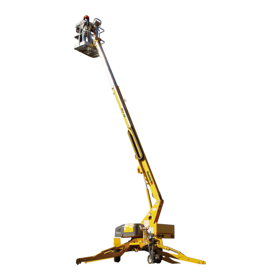
3 OPERATION 3 OPERATION The 3632T / HTT 13 Telescoping Boom Lift is a Summit Series™ trailer-mounted aerial work platform, designed and manufactured to position personnel with their tools and equipment at overhead work locations. The platform load capacity is rated at 500 pounds (227 kilograms). During all aerial work platform operations, four extended outriggers support the unit. - Page 20 HAULOTTE GROUP 3 OPERATION OPERATION (CONTINUED) Before attempting aerial work platform operations, operators should: Attend a training program as required by government regulations. Obtain, read and obey all safety precautions as indicated by manufacturer’s recommendations and all federal, state and local regulations.
- Page 21 HAULOTTE GROUP 3 OPERATION THIS PAGE INTENTIONALY LEFT BLANK...
-
Page 22: Ground Control Station
HAULOTTE GROUP 3 OPERATION GROUND CONTROL STATION The Ground Control Station is used to operate outriggers and control telescoping boom motion. To access the ground control station, open the control panel access cover found on the turntable. Turn the key switch to the ground controls setting. - Page 23 HAULOTTE GROUP 3 OPERATION 1. Key Switch Turning the key switch to the (1a) icon selects operation from the platform. Turning the key PLATFORM switch to the (1b) icon selects operation from the ground control panel. The center (power GROUND off) position interrupts all electric and hydraulic power operations except emergency lowering.
-
Page 24: Platform Control Station
HAULOTTE GROUP 3 OPERATION PLATFORM CONTROL STATION The platform control station is used to control telescoping boom motion. To access the platform control station, turn the key switch to the ground control station to the platform controls setting and enter the work cage. - Page 25 HAULOTTE GROUP 3 OPERATION Engine Start and Choke / Glow Plug (Models with Engines Only) 1-2. Start a cold engine by pressing the button (1), then, press the button (2) to start CHOKE ENGINE START the Engine. To start / restart a warm Engine, press the button only.
-
Page 26: Normal Operating Procedure
HAULOTTE GROUP 3 OPERATION NORMAL OPERATING PROCEDURE Perform the following procedures to operate the Haulotte Group Telescoping Boom Lift. Read and obey all safety precautions and operating instructions, as well as all applicable government regulations. Conduct a Pre-Operation Inspection by performing all recommended Daily Service Checks. -
Page 27: Figure 3-4. Platform Travel Latch
HAULOTTE GROUP 3 OPERATION NORMAL OPERATING PROCEDURE (CONTINUED) Open the platform travel latch and pivot the platform upright. Platform locking pins will engage in the pivot locking holes when the platform is in a full upright position. Verify that the platform is locked into place. -
Page 28: Figure 3-5. Outrigger Controls
HAULOTTE GROUP 3 OPERATION NORMAL OPERATING PROCEDURE (CONTINUED) Extend the outriggers individually or use the button. When the aerial work platform is AUTO LEVEL leveled properly, a buzzer will sound, the two LEDs at each button, and the LED at the OUTRIGGER button will be lit. - Page 29 HAULOTTE GROUP 3 OPERATION NORMAL OPERATING PROCEDURE (CONTINUED) Raise the safety bar and enter the work platform. Put on the safety harness and attach the lanyard to the F on the side of the platform support beam. ROTECTION TTACHMENT OINT ...
-
Page 30: Manual Boom Operation
HAULOTTE GROUP 3 OPERATION MANUAL BOOM OPERATION Manual retraction, rotation and lowering functions allow the telescoping boom lift to be moved and lowered during hydraulic power interruption or failure. The following procedures for manual retraction, rotation and lowering require a person on the ground to operate the manual controls and hand pump. -
Page 31: Figure 3-7. Emergency Boom Lowering Valve
HAULOTTE GROUP 3 OPERATION MANUAL BOOM OPERATION (CONTINUED) Emergency Boom Lowering Procedure Each lift cylinder is equipped with a manual lowering valve, found at the base of the lift cylinder. Use the valve handle to lower the platform in case of a complete electrical power failure, a load shift, or other emergency. -
Page 32: Aerial Work Platform Transport
HAULOTTE GROUP 3 OPERATION AERIAL WORK PLATFORM TRANSPORT The aerial work platform trailer includes a single axle, two-inch ball hitch, hydraulic surge brakes, mechanical parking brake, safety chains, brake lights and side marker lights. Proper aerial work platform transport requires the proper attachment and inspection of these components before towing. -
Page 33: Figure 3-9. Trailer Hitching
HAULOTTE GROUP 3 OPERATION AERIAL WORK PLATFORM TRANSPORT (CONTINUED) Procedure to hitch and tow the aerial work platform. Back the tow Vehicle to the trailer. Verify that the ball and hitch are aligned and that the trailer hitch has proper clearance above the ball. Use the tongue jack as needed. Refer to Figure 3-9. -
Page 34: Figure 3-10.Transport Instruction
HAULOTTE GROUP 3 OPERATION TRANSPORT INSTRUCTIONS Refer to Figure 3-10. Verify that truck or trailer is parked on a firm and level surface. Completely lower and retract telescoping boom. Secure telescoping boom and platform travel latches. ... -
Page 35: Figure 3-11. Lift Instruction
HAULOTTE GROUP 3 OPERATION LIFTING INSTRUCTIONS Refer to Figure 3-11. Completely lower and retract telescoping boom. Secure telescoping boom and platform travel latches (A). Remove all loose materials from machine. Retract all outriggers to fully stowed position. - Page 36 HAULOTTE GROUP 3 OPERATION...
-
Page 37: Equipment Maintenance
Refer to the Parts and Service Manual for a list of annual service checks. It is the practice of Haulotte Group to issue Service and / or Safety Bulletins, which may include updates to the information contained in this manual. In such instances, procedures contained in Haulotte Group Service Bulletins or Safety Bulletins supersede the information contained in manual. -
Page 38: Battery Recharge
HAULOTTE GROUP 4 EQUIPMENT MAINTENANCE BATTERY RECHARGE Recharge aerial work platform batteries after each 8-hour work shift or as needed. When the aerial work platform is not in use, batteries should be recharged at least once per week. Under normal circumstances, battery recharge should take approximately 10-12 hours. - Page 39 HAULOTTE GROUP 4 EQUIPMENT MAINTENANCE BATTERY RECHARGE (CONTINUED) If a Battery fault is detected, the appropriate fault code will appear on the charge current display. The red check battery indicator LED will become lit. Refer to Table 4-1 for battery charger fault codes.
-
Page 40: Daily Service Checks
HAULOTTE GROUP 4 EQUIPMENT MAINTENANCE DAILY SERVICE CHECKS The following Maintenance Procedures should be performed daily or before each operation: Verify that all decals are correctly applied and in plain view. Refer to the “Decal Replacement” Section of this Manual for decal locations. -
Page 41: Figure 4-2. Outrigger Position Switches
HAULOTTE GROUP 4 EQUIPMENT MAINTENANCE DAILY SERVICE CHECKS (CONTINUED) Verify that outrigger safety interlocks operate correctly. Begin with the outriggers fully extended and the aerial work platform level. Raise one outrigger until the footpad is not in contact with the ground. -
Page 42: Figure 4-3. Hydraulic Reservoir
HAULOTTE GROUP 4 EQUIPMENT MAINTENANCE DAILY SERVICE CHECKS (CONTINUED) Inspect hydraulic System and fluid levels. Check all hydraulic hoses and fittings for leaks and / or damage. Tighten or replace as necessary to prevent hydraulic oil or pressure loss. -
Page 43: Weekly Service Checks
HAULOTTE GROUP 4 EQUIPMENT MAINTENANCE WEEKLY SERVICE CHECKS Perform the following service checks at least once each week in addition to all recommended Daily Service Checks: Check Battery Electrolyte level. If battery charge is low, add enough water to bring the electrolyte level to the top of the plates. -
Page 44: Monthly Service Checks
HAULOTTE GROUP 4 EQUIPMENT MAINTENANCE MONTHLY SERVICE CHECKS Perform the following service checks at least once each month: Clean all battery terminals. Check battery for loose connections or damaged wires. Verify proper operation of manual lowering valves and hand pump. -
Page 45: Additional Service Information
Testing Aerial Work Platform Stability The Summit Series aerial work platform has been tested for stability using a load equal to 150% of the rated capacity of the machine and placed at the center of the platform with the telescoping boom fully extended. -
Page 46: Troubleshooting
TROUBLESHOOTING Refer to the following Table for basic Troubleshooting Operations. Additional information can be found in the Haulotte Group Parts and Service Manual. Contact the Haulotte Group Service Department with any questions or before attempting any advanced troubleshooting operations. TABLE 4-2. TROUBLE SHOOTING... -
Page 47: Error Code Definitions - Controls
HAULOTTE GROUP 4 EQUIPMENT MAINTENANCE ERROR CODE DEFINITIONS – CONTROLS The DISPLAY PANEL located on the ground control panel indicates the present operating status of the aerial work platform. If an error condition is detected, the appropriate error code will be displayed on this panel. - Page 48 HAULOTTE GROUP 4 EQUIPMENT MAINTENANCE TABLE 4-3 ERROR CODE DEFINITIONS ERROR MESSAGE ERROR DEFINITION TO SIMULATE ERROR TO CLEAR ERROR COMMENTS 014 CHECK ENGINE Engine had low oil Kawasaki Engine: While This is a latched error. X-Boom Machines with LOW OIL...
- Page 49 HAULOTTE GROUP 4 EQUIPMENT MAINTENANCE TABLE 4-3 ERROR CODE DEFINITIONS ERROR MESSAGE ERROR DEFINITION TO SIMULATE ERROR TO CLEAR ERROR COMMENTS 028 SHORTED CIRCUIT Excessive load was Use a piece of wire to This is a latched error. Checked only at...
- Page 50 HAULOTTE GROUP 4 EQUIPMENT MAINTENANCE TABLE 4-3 ERROR CODE DEFINITIONS ERROR MESSAGE ERROR DEFINITION TO SIMULATE ERROR TO CLEAR ERROR COMMENTS 044 SHORTED CIRCUIT Excessive load was Use a piece of wire to This is a latched error. Checked only at...
- Page 51 HAULOTTE GROUP 4 EQUIPMENT MAINTENANCE TABLE 4-3 ERROR CODE DEFINITIONS ERROR MESSAGE ERROR DEFINITION TO SIMULATE ERROR TO CLEAR ERROR COMMENTS 059 OPEN CIRCUIT A load of less than 70mA Disconnect a wire from This is a latched error. Checked only at...
- Page 52 HAULOTTE GROUP 4 EQUIPMENT MAINTENANCE TABLE 4-3 ERROR CODE DEFINITIONS ERROR MESSAGE ERROR DEFINITION TO SIMULATE ERROR TO CLEAR ERROR COMMENTS 074 SHORTED CIRCUIT Excessive load was Use a piece of wire to This is a latched error. Not Used...
- Page 53 HAULOTTE GROUP 4 EQUIPMENT MAINTENANCE TABLE 4-3 ERROR CODE DEFINITIONS ERROR MESSAGE ERROR DEFINITION TO SIMULATE ERROR TO CLEAR ERROR COMMENTS 089 OPEN CIRCUIT A load of less than 70mA Disconnect a wire from This is a latched error. Checked only at...
- Page 54 HAULOTTE GROUP 4 EQUIPMENT MAINTENANCE TABLE 4-3 ERROR CODE DEFINITIONS ERROR MESSAGE ERROR DEFINITION TO SIMULATE ERROR TO CLEAR ERROR COMMENTS 104 OUTREACH Boom has reached Put 500lbs in boom, level This is a self clearing Machines with Moment AT MAXIMUM...
- Page 55 HAULOTTE GROUP 4 EQUIPMENT MAINTENANCE TABLE 4-3 ERROR CODE DEFINITIONS ERROR MESSAGE ERROR DEFINITION TO SIMULATE ERROR TO CLEAR ERROR COMMENTS 129 OPEN CIRCUIT A load of less than 70mA Disconnect a wire from This is a latched error. Checked only at...
- Page 56 HAULOTTE GROUP 4 EQUIPMENT MAINTENANCE TABLE 4-3 ERROR CODE DEFINITIONS ERROR MESSAGE ERROR DEFINITION TO SIMULATE ERROR TO CLEAR ERROR COMMENTS 144 SHORTED CIRCUIT Excessive load was Use a piece of wire to This is a latched error. Checked only at...
- Page 57 HAULOTTE GROUP 4 EQUIPMENT MAINTENANCE TABLE 4-3 ERROR CODE DEFINITIONS ERROR MESSAGE ERROR DEFINITION TO SIMULATE ERROR TO CLEAR ERROR COMMENTS 159 OPEN CIRCUIT A load of less than 70mA Disconnect a wire from This is a latched error. Checked only at...
-
Page 58: Error Code Definitions - Motor Controller
HAULOTTE GROUP 4 EQUIPMENT MAINTENANCE ERROR CODE DEFINITIONS – MOTOR CONTROLLER The Motor Controller, located under the left power (driver side) compartment cover (behind the lower control box), indicates the operational status of the controller. If an error condition is detected, the appropriate error code will be displayed by a flashing indicator light. -
Page 59: Figure 3-7. Motor Controller
HAULOTTE GROUP 4 EQUIPMENT MAINTENANCE TABLE 4-3. ERROR CODE DEFINITIONS - MOTOR CONTROLLER FLASH PRIORITY ID FAULT DESCRIPTION SOLUTION FAULT Auto Zero Out of Internal pump current Replace motor controller. Range measurement circuit could not be calibrated. System Monitor Illegal system condition sensed Replace motor controller. - Page 60 HAULOTTE GROUP 4 EQUIPMENT MAINTENANCE...
-
Page 61: Decal Replacement
HAULOTTE GROUP 5 DECAL REPLACEMENT 5 DECAL REPLACEMENT WARNING Decals contain information that is required for the safe and proper use of the aerial work platform. Decals should be considered necessary components of the machine and should be checked before each use to verify that they are correctly attached and legible. -
Page 62: Decal Replacement - Decal Kit - Ansi
HAULOTTE GROUP 5 DECAL REPLACEMENT DECAL REPLACEMENT – DECAL KIT - ANSI... - Page 63 HAULOTTE GROUP 5 DECAL REPLACEMENT DECAL REPLACEMENT – DECAL KIT - ANSI B06-01-4002 DECAL KIT – Includes the following: ITEM NO. PART NUMBER DESCRIPTION QTY. B06-00-0471 Decal - Danger - Main Instruction / Hazard - Platform B06-00-0475 Decal - Warning - Read / Understand Manual...
-
Page 64: Decal Replacement - Identification Plates & Optional Equipment Ansi
HAULOTTE GROUP 5 DECAL REPLACEMENT DECAL REPLACEMENT – IDENTIFICATION PLATES & OPTIONAL EQUIPMENT ANSI... - Page 65 HAULOTTE GROUP 5 DECAL REPLACEMENT DECAL REPLACEMENT – IDENTIFICATION PLATES & OPTIONAL EQUIPMENT ANSI IDENTIFICATION PLATES (Used on all standard equipment) ITEM NO. PART NUMBER DESCRIPTION QTY. B06-00-0526 Key Ring Tag B06-00-0524 Annual Inspection Plate B06-00-0490 VIN Plate B06-00-0499 ANSI ID Plate DECALS FOR OPTIONAL EQUIPMENT - ANSI ITEM NO.
-
Page 66: Decal Replacement - Decal Kit - Ce
HAULOTTE GROUP 5 DECAL REPLACEMENT DECAL REPLACEMENT – DECAL KIT - CE... - Page 67 HAULOTTE GROUP 5 DECAL REPLACEMENT DECAL REPLACEMENT – DECAL KIT – CE B06-01-4002-DU DECAL KIT - Dutch - Includes the following: B06-01-4002-EI DECAL KIT - English International - Includes the following: B06-01-4002-FC DECAL KIT - French (Canadian) - Includes the following:...
-
Page 68: Decal Replacement - Identification Plates & Optional Equipment Ce
HAULOTTE GROUP 5 DECAL REPLACEMENT DECAL REPLACEMENT – IDENTIFICATION PLATES & OPTIONAL EQUIPMENT... - Page 69 HAULOTTE GROUP 5 DECAL REPLACEMENT DECAL REPLACEMENT – IDENTIFICATION PLATES & OPTIONAL EQUIPMENT IDENTIFICATION PLATES (Used on all standard CE equipment) ITEM NO. PART NUMBER DESCRIPTION QTY. B06-00-0499-CE ID Plate B06-00-0490 VIN Plate DECALS FOR OPTIONAL EQUIPMENT – CE ITEM NO.
- Page 70 HAULOTTE GROUP 5 DECAL REPLACEMENT...
-
Page 71: Optional Equipment
HAULOTTE GROUP 6 OPTIONAL EQUIPMENT 6 OPTIONAL EQUIPMENT The Haulotte Group Model 3632T / HTT 13 may be equipped with one or more optional components designed for the convenience and safety of operators when using the equipment to accomplish specific tasks. -
Page 72: Drive And Set
HAULOTTE GROUP 6 OPTIONAL EQUIPMENT DRIVE AND SET The Drive and Set Option allows the operator to drive the aerial work platform, deploy, retract and level the outriggers from the platform controls. To operate the Drive and Set option the aerial work platform must be in its fully lowered position. -
Page 73: Figure 6-1. Jockey Wheel Instruction
HAULOTTE GROUP 6 OPTIONAL EQUIPMENT DRIVE AND SET USE Use the following procedure to operate an aerial work platform equipped with the Drive and Set option: Set parking brake. Drive function will not operate unless parking brake is set. -
Page 74: Figure 6-2. Drive And Set Controls
HAULOTTE GROUP 6 OPTIONAL EQUIPMENT DRIVE AND SET CONTROLS The platform control station is used to control boom motion and drive and set functions, including outrigger deployment. To access the platform control station, turn the key switch at the ground control station to the platform controls setting and enter the work cage. - Page 75 HAULOTTE GROUP 6 OPTIONAL EQUIPMENT 1. Drive and Set Joystick. Move the joystick in the desired direction while pressing and holding the (2) button DRIVE ENABLE to drive the fully retracted aerial work platform. Release the (2) button or joystick to DRIVE ENABLE stop.
-
Page 76: Material Lift Hook
HAULOTTE GROUP 6 OPTIONAL EQUIPMENT MATERIAL LIFT HOOK If the aerial work platform is equipped with a Material Lifting Hook, observe the following procedure for material lift operation: Remove the Platform Control Box from the work platform by releasing the latch on the back of the control box. -
Page 77: Figure 6-5. Platform Removal
HAULOTTE GROUP 6 OPTIONAL EQUIPMENT MATERIAL LIFT HOOK (CONTINUED) Firmly secure the platform to prevent equipment damage. Remove the clevis pin holding the platform to the boom lift. See Figure 6-5 Remove the platform from the boom by lifting the cage up and away from the mounting bracket on the boom nose. -
Page 78: Figure 6-7. Material Lift Stow Position
HAULOTTE GROUP 6 OPTIONAL EQUIPMENT MATERIAL LIFT HOOK (CONTINUED) Figure 6-7. Material Lift Stow Position. Figure 6-8. Material Lift “In Use” Position WARNING ALWAYS observe the manufacturer’s weight lifting limitations when using the material lifting hook. Always use lifting straps or wire rope slings that are rated at a minimum 500 lbs. -
Page 79: Load Cell Calibration Procedure
13) Adjust displayed weight by pressing mid-high or mid-low speed until weight is within tolerances, exit maintenance mode. The Ratio should be within 3.50:1 to 4.00:1. If so, continue on to Step 14. If the ratio is not within the above values, contact Haulotte Group Customer Service Department: 1-888- 440-9240. -
Page 80: Platform Rotator
HAULOTTE GROUP 6 OPTIONAL EQUIPMENT PLATFORM ROTATOR The optional platform rotator allows the operator to rotate the elevated work platform 90º around a vertical axis by actuating a rotator handle found below the platform control panel. See Figure 7-5. To operate manual platform rotator, turn the rotator handle in the direction of desired rotation (clockwise or counterclockwise). -
Page 81: Material Safety
HAULOTTE GROUP 7 MATERIAL SAFETY 7 MATERIAL SAFETY The following Material Safety Data Sheets describe the correct procedures for the safe handling of chemical components within the Model 3632T / HTT 13 Telescoping Boom Lift, as well as any potential health and safety hazards related to these chemicals. Material Safety Data Sheets are included here in accordance with applicable federal and state regulations. - Page 82 HAULOTTE GROUP 7 MATERIAL SAFETY MATERIAL SAFETY DATA SHEET FOR LEAD ACID BATTERIES, WET, FILLED WITH ACID (CONTINUED) SECTION V -- HEALTH HAZARD DATA Primary Routes of Entry: Inhalation: YES Skin: Ingestion: Health Hazards: Acute EYES, SKIN, RESPIRATORY SYSTEM & DIGESTIVE SYSTEM Chronic: EYES, SKIN, RESPIRATORY SYSTEM &...
- Page 83 HAULOTTE GROUP 7 MATERIAL SAFETY MATERIAL SAFETY DATA SHEET DEXRON III/MERCON AUTOMATIC TRANSMISSION FLUID (HYDRAULIC OIL)
- Page 84 HAULOTTE GROUP 7 MATERIAL SAFETY MATERIAL SAFETY DATA SHEET DEXRON III/MERCON AUTOMATIC TRANSMISSION FLUID (HYDRAULIC OIL) (CONTINUED)
- Page 85 HAULOTTE GROUP 7 MATERIAL SAFETY MATERIAL SAFETY DATA SHEET DEXRON III/MERCON AUTOMATIC TRANSMISSION FLUID (HYDRAULIC OIL) (CONTINUED)
- Page 86 HAULOTTE GROUP 7 MATERIAL SAFETY MATERIAL SAFETY DATA SHEET DEXRON III/MERCON AUTOMATIC TRANSMISSION FLUID (HYDRAULIC OIL) (CONTINUED)
- Page 87 HAULOTTE GROUP 7 MATERIAL SAFETY MATERIAL SAFETY DATA SHEET DEXRON III/MERCON AUTOMATIC TRANSMISSION FLUID (HYDRAULIC OIL) (CONTINUED)
- Page 88 HAULOTTE GROUP 7 MATERIAL SAFETY MATERIAL SAFETY DATA SHEET DEXRON III/MERCON AUTOMATIC TRANSMISSION FLUID (HYDRAULIC OIL) (CONTINUED)
- Page 89 HAULOTTE GROUP 7 MATERIAL SAFETY MATERIAL SAFETY DATA SHEET DEXRON III/MERCON AUTOMATIC TRANSMISSION FLUID (HYDRAULIC OIL) (CONTINUED)
- Page 90 HAULOTTE GROUP 7 MATERIAL SAFETY...
-
Page 91: Ansi Reprint
The following sections are reprinted from the ANSI A92.2-2009 code in effect at the time of manufacture and govern the safe use of the Haulotte Group. It is the responsibility of all owners and operators of this machine to read, understand and obey the recommendations set forth by the ANSI code. - Page 92 HAULOTTE GROUP 8 ANSI REPRINT (3) Check visual and audible safety devices for proper methods and procedures as outlined in section operation. 5.4.3 of this standard: (4) Visually inspect fiberglass and insulating (a) If the aerial device is used for ac bare-hand components for visible damage and contamination.
- Page 93 HAULOTTE GROUP 8 ANSI REPRINT correction shall be maintained for five years, or as 8.12 Training, Retraining, and Familiarization of required by applicable regulations. Operators. 8.3.2 Periodic. Written, or appropriately archived electronic, 8.12.1 General Training. Only personnel who have received...
- Page 94 HAULOTTE GROUP 8 ANSI REPRINT (2) That operating manuals are an integral part of the Lower Controls. The lower controls of aerial devices aerial device and must be properly stored on the shall not be used for continuous operation with vehicle when not in use.
- Page 95 HAULOTTE GROUP 8 ANSI REPRINT Any suspected items shall be carefully examined or tested and a other industries using aerial devices have safety determination made by a qualified person as to whether they rules pertinent to that industry. constitute a safety hazard. All unsafe items shall be replaced or (9) Authorization to operate.
-
Page 96: Figure 8-1. Minimum Safe Approach Distance
HAULOTTE GROUP 8 ANSI REPRINT 11.3.2 Responsibilities. Upon delivery, each lessor of an shall be instructed, prior to operating the aerial device, aerial device shall inform the lessee of their regarding the following items: responsibilities in accordance with Section 8 as to (1) The location of the manuals. -
Page 97: Table 8-1. Minimum Safe Approach Distances
HAULOTTE GROUP 8 ANSI REPRINT TABLE 8-1. MINIMUM SAFE APPROACH DISTANCES Minimum Safe Approach Distance Voltage Range (Phase to Phase) (Feet) (Meters) 0 to 300V Avoid Contact Over 300V to 50KV 3.05 Over 50KV to 200KV 4.60 Over 200KV to 350KV 6.10... - Page 98 HAULOTTE GROUP 8 ANSI REPRINT...
-
Page 99: Inspection Form For Haulotte Group Aerial Work Platforms
All service checks shall be performed in accordance with manufacturer’s recommendations (see the appropriate Parts and Service Manual) and ANSI / SIA A92 Standard. Copy this form as needed. Direct any questions to the Haulotte Group Customer Service Department: 1-888-440-9240 or visit Haulotte Group online at www.haulotte-usa.com. - Page 100 Distributed by: 125 Taylor Parkway Archbold, Ohio 43502 Phone (800) 537-0540 (419) 445-8915 (419) 445-0367 www.haulotte-usa.com...
Need help?
Do you have a question about the Summit Series and is the answer not in the manual?
Questions and answers