
Related Manuals for Haulotte Group HA20RTJ


Summary of Contents for Haulotte Group HA20RTJ
- Page 1 Maintenance Book Maintenance Book HA20RTJ - HA20RTJ O - HA20RTJ PRO HA61RTJ O - HA61RTJ PRO 4000427880 E 12.15 US / GB...
- Page 2 HA20RTJ - HA20RTJ O - HA20RTJ PRO - HA61RTJ O - HA61RTJ PRO 4000427880 E 12.15 US / GB...
-
Page 3: Table Of Contents
Maintenance Book CONTENTS Preface - Foreword 1 - Symbols and colors ..... . Safety 1 - General safety rules ..... 1.1 - Maintenance implementation. - Page 4 Maintenance Book Familiarization 1 - Primary machine components ... . 1.1 - Layout............1.2 - Ground control box .
- Page 5 Maintenance Book Inspection and maintenance schedule 1 - Maintenance Schedule ....2 - Inspection program ..... 3 - Daily inspection .
- Page 6 Maintenance Book Boom and arm pads adjustment ..MS0075 - Remove / Re-install turret/platform CAN BUS MS0076 - wiring harness ......Remove / Re-install load cell .
-
Page 7: Preface - Foreword
HA20RTJ - HA20RTJ O - HA20RTJ PRO - HA61RTJ O - HA61RTJ PRO - Preface - Foreword Preface - Foreword Preface - Foreword You have just purchased a HAULOTTE® product and we would like to thank you for your business. -
Page 8: Symbols And Colors
HA20RTJ - HA20RTJ O - HA20RTJ PRO - HA61RTJ O - HA61RTJ PRO - Preface - Foreword 1 - Symbols and colors Symbols and colors are used to alert the operator of safety precautions and/or to highlight important safety information. - Page 9 HA20RTJ - HA20RTJ O - HA20RTJ PRO - HA61RTJ O - HA61RTJ PRO - Preface - Foreword Decals Color Title Description Danger : Indicates a hazardous situation which if not avoided, WILL result in death or serious injury. Warning : Indicates a hazardous situation which if not avoided, COULD result in death or serious injury.
- Page 10 HA20RTJ - HA20RTJ O - HA20RTJ PRO - HA61RTJ O - HA61RTJ PRO - Preface - Foreword Notes 4000427880 E 12.15 US / GB...
-
Page 11: Safety
HA20RTJ - HA20RTJ O - HA20RTJ PRO - HA61RTJ O - HA61RTJ PRO - Safety Safety 1 - General safety rules 1.1 - AINTENANCE IMPLEMENTATION Your safety and the safety of the people around are essential. Make sure the work area is clean in order to not to pollute the system of the machine. -
Page 12: Uncontrolled Movement Hazard
HA20RTJ - HA20RTJ O - HA20RTJ PRO - HA61RTJ O - HA61RTJ PRO - Safety Report that the machine is under maintenance by tagging the platform and ground control boxes. Note : • Using the machine during maintenance is strictly forbidden. -
Page 13: Electrocution Hazards
HA20RTJ - HA20RTJ O - HA20RTJ PRO - HA61RTJ O - HA61RTJ PRO - Safety 1.3 - LECTROCUTION AZARDS The machine is not electrically insulated and does not provide protection from contact or proximity to electrically charged conductors. Always position the lift at a safe distance from electrically charged conductors to ensure that no part of the machine is within an unsafe area. -
Page 14: Explosion / Fire Hazards
HA20RTJ - HA20RTJ O - HA20RTJ PRO - HA61RTJ O - HA61RTJ PRO - Safety 1.4 - XPLOSION AZARDS Always wear protective clothing and eye wear when working with batteries and power sources/systems. N.B.-:-A CID IS NEUTRALIZED WITH SODIUM BICARBONATE AND WATER •... -
Page 15: Maintenance And Repair Training
HAULOTTE S ® ERVICES The HAULOTTE Group is at your service in all 5 continents of the world via an extensive network of its own factory trained technicians, who are ready to respond to your every need. 2.4 - RAINING Whether you want to just service your equipment or carry out a complete overhaul, HAULOTTE®... -
Page 16: Product Modification
Any modification may violate Haulotte design parameters, government regulations and industry standards. If you desire a modification to the product, submit a request in writing to HAULOTTE Group. With the utmost care to ensure enhanced reliability and greater safety of the HAULOTTE® products, it is pertinent that when a "Service or Safety Bulletin"... -
Page 17: Manufacturer's Warranty
HA20RTJ - HA20RTJ O - HA20RTJ PRO - HA61RTJ O - HA61RTJ PRO - Safety 3 - Manufacturer's warranty 3.1 - ARRANTY ACCEPTANCE On reception of his machine, the owner or rental company must check the machine's condition and fill out the machine reception slip provided. -
Page 18: Warranty Conditions
HA20RTJ - HA20RTJ O - HA20RTJ PRO - HA61RTJ O - HA61RTJ PRO - Safety If no particular agreement has been made, any claims made after the previously established warranty period has expired will be refused. The present warranty does not cover damage that may result directly or indirectly from any flaws or defects covered by the latter : •... - Page 19 HA20RTJ - HA20RTJ O - HA20RTJ PRO - HA61RTJ O - HA61RTJ PRO - Familiarization Familiarization Notes 4000427880 E 12.15 US / GB...
-
Page 20: Primary Machine Components
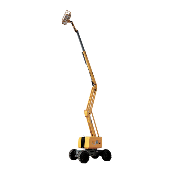
HA20RTJ - HA20RTJ O - HA20RTJ PRO - HA61RTJ O - HA61RTJ PRO - Familiarization 1 - Primary machine components 1.1 - AYOUT HA20RTJ - HA20RTJO - HA20RTJPRO - HA61RTJO - HA61RTJPRO C163 C4 C150 C8 C113 C164 C165 4000427880 E 12.15... - Page 21 HA20RTJ - HA20RTJ O - HA20RTJ PRO - HA61RTJ O - HA61RTJ PRO - Familiarization Marking Description Marking Description Chassis Boom lift cylinder Steering wheel Arm lifting cylinder Rear drive wheel (and steer wheel if Ground control box 4WS) Tilt sensor...
-
Page 22: Ground Control Box
HA20RTJ - HA20RTJ O - HA20RTJ PRO - HA61RTJ O - HA61RTJ PRO - Familiarization 1.2 - ROUND CONTROL BOX 1.2.1 - Layout General view Afficheur (1 - 10) LED’s display panel 4000427880 E 12.15 US / GB... - Page 23 HA20RTJ - HA20RTJ O - HA20RTJ PRO - HA61RTJ O - HA61RTJ PRO - Familiarization Controls and indicators Marking Description Function Move upwards : Jib lifting Jib lifting / lowering switch Move downwards : Jib lowering Move to the left : Boom extension...
-
Page 24: Display Panel (Led's 1 - 10)
HA20RTJ - HA20RTJ O - HA20RTJ PRO - HA61RTJ O - HA61RTJ PRO - Familiarization 1.2.2 - Display Panel (LED'S 1 - 10) Indicators / Cluster Marking Description Overriding system : LED 1 • Stays illuminated with Overriding system switch ( 245 ) in use. - Page 25 HA20RTJ - HA20RTJ O - HA20RTJ PRO - HA61RTJ O - HA61RTJ PRO - Familiarization Symbol Description Illuminated when service counter is displayed • Illuminated when engine is not running or when hour meter is displayed • Flashing engine in operation...
-
Page 26: Platform Control Box
HA20RTJ - HA20RTJ O - HA20RTJ PRO - HA61RTJ O - HA61RTJ PRO - Familiarization 1.3 - LATFORM CONTROL BOX 1.3.1 - Layout General view Affichage pupitre de commandes haut (Led 101 - 117) Platform control box display (Led’s 101 - 117) - Page 27 HA20RTJ - HA20RTJ O - HA20RTJ PRO - HA61RTJ O - HA61RTJ PRO - Familiarization Marking Description Function High-speed drivie Drive speed selector Medium speed drive Low-speed drive Pulled out : Platform control box energized E-stop button Pressed in : De-energizes control system (Engine stopped)
-
Page 28: Display Panel (Led's 101 - 117)
HA20RTJ - HA20RTJ O - HA20RTJ PRO - HA61RTJ O - HA61RTJ PRO - Familiarization 1.3.2 - Display Panel (LED'S 101 - 117) Platform control box display LED 101 LED 102 LED 103 LED 104 LED 105 LED 106 LED 107... - Page 29 HA20RTJ - HA20RTJ O - HA20RTJ PRO - HA61RTJ O - HA61RTJ PRO - Familiarization Symbol Description Machine switched on : • Rapid flashing : Machine is ON, but platform control panel is not active but the ground control panel is ON.
- Page 30 HA20RTJ - HA20RTJ O - HA20RTJ PRO - HA61RTJ O - HA61RTJ PRO - Familiarization Filter status Level of clogging DPF cannot be recovered > 250% Manual regeneration required (high level) 250% - 180% Automatic or manual regeneration required (medium level -> regeneration deactivation...
- Page 31 HA20RTJ - HA20RTJ O - HA20RTJ PRO - HA61RTJ O - HA61RTJ PRO - Familiarization Notes 4000427880 E 12.15 US / GB...
-
Page 32: Device Layout
HA20RTJ - HA20RTJ O - HA20RTJ PRO - HA61RTJ O - HA61RTJ PRO - Familiarization 2 - Device layout 2.1 - ENSORS AND ACTUATORS Sensors and actuators SR721 - SR720 SP800 - SP801 SQ531- SQ530 SQ520 SQ421 YV620 U/D YV750 R/L... - Page 33 HA20RTJ - HA20RTJ O - HA20RTJ PRO - HA61RTJ O - HA61RTJ PRO - Familiarization Description Name Control's pressure for oscillating axle sensor SP109 Engine oil pressure sensor ( TIER III engine only) SP300 Weight gauge sensor SP800 Weight gauge sensor...
-
Page 34: Power Source - Engine Specifications
HA20RTJ - HA20RTJ O - HA20RTJ PRO - HA61RTJ O - HA61RTJ PRO - Familiarization 3 - Power source - Engine specifications 3.1 - ENERAL SAFETY AND SPECIFIC INTERVENTIONS ON MOTOR The technician should take all steps to protect themselves or others against all risks of injury inherent in his intervention. -
Page 35: Consumables
HA20RTJ - HA20RTJ O - HA20RTJ PRO - HA61RTJ O - HA61RTJ PRO - Familiarization 3.3 - ONSUMABLES Consumable HAULOTTE® code Air cleaner : 2324007620 • Primary cartridge 4000044230 • Secondary cartridge 4000044240 Pressure filter 4000228480 Oil filter 4000007260 Engine fuel filter... -
Page 36: Lubrication Diagram
HA20RTJ - HA20RTJ O - HA20RTJ PRO - HA61RTJ O - HA61RTJ PRO - Familiarization 4 - Lubrication diagram List of ingredients HAULOTTE® Marking Ingredient Symbol code Engine oil (+30° / - 20° ) 2820305720 Gear box oil - Can 20 l(5,3 gal US) -
Page 37: Greasing Points Localization
HA20RTJ - HA20RTJ O - HA20RTJ PRO - HA61RTJ O - HA61RTJ PRO - Familiarization HAULOTTE® Marking Ingredient Symbol code Lead-free grease - Aerosol 0,4 l(0.1 gal US) 2820304330 Lead-free grease - Can 5 l(1,32 gal US) 2820304340 4.1 -... - Page 38 HA20RTJ - HA20RTJ O - HA20RTJ PRO - HA61RTJ O - HA61RTJ PRO - Familiarization Slew ring : • 2 nipples on the raceways inside the slew ring • 3 nipples on the worm screw • Greasing the crown gear teeth 4000427880 E 12.15...
- Page 39 HA20RTJ - HA20RTJ O - HA20RTJ PRO - HA61RTJ O - HA61RTJ PRO - Familiarization • Greasing the sidewall telescope 4000427880 E 12.15 US / GB...
-
Page 40: Consumables (Oils - Fuels - Engine Oil - Coolant Level
HA20RTJ - HA20RTJ O - HA20RTJ PRO - HA61RTJ O - HA61RTJ PRO - Familiarization 5 - Consumables (Oils - Fuels - Engine oil - Coolant level...) 5.1 - N.B.-:-T HESE FUELS CAN BE USED ON ANY TYPE OF MECHANICAL INJECTION ENGINE... -
Page 41: Other Fuels
HA20RTJ - HA20RTJ O - HA20RTJ PRO - HA61RTJ O - HA61RTJ PRO - Familiarization 5.1.1 - Other fuels • Biofuels : According to EN14214 (EU) and ASTM D6751-07a (USA) biofuels are allowed on some engines and under certain conditions. For more information, please contact HAULOTTE Services®. -
Page 42: Hydraulic Oil
HA20RTJ - HA20RTJ O - HA20RTJ PRO - HA61RTJ O - HA61RTJ PRO - Familiarization Classification API Engine oil classification Fuel type Engines with non EGR Engines with internal EGR High sulfur fuel ? [0.05% (500 ppm)] (If the engine oil is used with a high sulfur level, change Sulfur content <... -
Page 43: Machine Specifications
HA20RTJ - HA20RTJ O - HA20RTJ PRO - HA61RTJ O - HA61RTJ PRO - Familiarization 6 - Machine specifications 6.1 - OVEMENT SPEED To allow checking operation, refer to the following table about originally time per movement. If the values measured by test are not equal to the following : •... - Page 44 HA20RTJ - HA20RTJ O - HA20RTJ PRO - HA61RTJ O - HA61RTJ PRO - Familiarization Notes 4000427880 E 12.15 US / GB...
-
Page 45: Maintenance Schedule
HA20RTJ - HA20RTJ O - HA20RTJ PRO - HA61RTJ O - HA61RTJ PRO - Inspection and maintenance schedule Inspection and maintenance schedule 1 - Maintenance Schedule The Aerial Work Platform was given an arbitrary Design Life of 10 years at the design stage of the product. There are a number of factors which can affect the design life including but not limited to, severity of operating conditions/routine maintenance which should be carried out in accordance with this manual. - Page 46 HA20RTJ - HA20RTJ O - HA20RTJ PRO - HA61RTJ O - HA61RTJ PRO - Inspection and maintenance schedule Wear pads Cylinder and hydraulic component : pump, filters, manifold Hydraulic oil Hydraulic oil filter Adjusting the hydraulic pressure Energy storage and motorisation : talns, batteries and engine...
-
Page 47: Inspection Program
HA20RTJ - HA20RTJ O - HA20RTJ PRO - HA61RTJ O - HA61RTJ PRO - Inspection and maintenance schedule 2 - Inspection program The machine must be inspected on a regular basis at intervals in accordance with the requirements set forth in the Country of use but no less than once a year. -
Page 48: Daily Inspection
HA20RTJ - HA20RTJ O - HA20RTJ PRO - HA61RTJ O - HA61RTJ PRO - Inspection and maintenance schedule 3 - Daily inspection The content and method of inspection must be conducted by operators before using the machine, it includes a visual inspection and functional and security systems testing of the machine. - Page 49 HA20RTJ - HA20RTJ O - HA20RTJ PRO - HA61RTJ O - HA61RTJ PRO - Inspection and maintenance schedule Daily inspection Visual inspection without disassembly Levelling To check by test Corrected applicable Manuals and displays. Clean or replace if necessary. Presence, cleanliness and legibility of the manufacturer's plate...
- Page 50 HA20RTJ - HA20RTJ O - HA20RTJ PRO - HA61RTJ O - HA61RTJ PRO - Inspection and maintenance schedule No cracks, broken weld, paint chipped No visible damage No screws missing / loose parts No foreign items in joints or slides...
- Page 51 HA20RTJ - HA20RTJ O - HA20RTJ PRO - HA61RTJ O - HA61RTJ PRO - Inspection and maintenance schedule No screws missing / loose parts Presence and good condition of hydraulic hose Presence and good condition of engine components Presence and good condition of the batteries: terminations and clamps, electrolyte level ...
-
Page 52: Periodic Inspection
HA20RTJ - HA20RTJ O - HA20RTJ PRO - HA61RTJ O - HA61RTJ PRO - Inspection and maintenance schedule 4 - Periodic inspection The Periodic inspection is a thorough inspection of the operation and safety features of the machine. It must take place before the sale / resale of the machine and at a frequency of 6 months or 1 year according to regulations. - Page 53 HA20RTJ - HA20RTJ O - HA20RTJ PRO - HA61RTJ O - HA61RTJ PRO - Inspection and maintenance schedule Periodic inspection In addition to the daily inspection program Visual inspection without disassembly To check by test Visual inspection with small disassembly or movement Levelling needed to reach the part.
- Page 54 HA20RTJ - HA20RTJ O - HA20RTJ PRO - HA61RTJ O - HA61RTJ PRO - Inspection and maintenance schedule No deterioration and visible damage No screws missing / loose parts Presence and fastening of external wire guide Anchor points for handling fixed, undamaged and signalized (if...
- Page 55 HA20RTJ - HA20RTJ O - HA20RTJ PRO - HA61RTJ O - HA61RTJ PRO - Inspection and maintenance schedule No deformation, visible damage, and broken weld on hydraulic tank Absence of foreign body on surfaces Hydraulic oil level (complete if needed)
- Page 56 HA20RTJ - HA20RTJ O - HA20RTJ PRO - HA61RTJ O - HA61RTJ PRO - Inspection and maintenance schedule Slope limiting device operates properly The travel speed limiting device operate properly Test and if needed adjustment of load sensing system Test and if needed adjustment of work area limitation device (if...
-
Page 57: Reinforced Inspection
HA20RTJ - HA20RTJ O - HA20RTJ PRO - HA61RTJ O - HA61RTJ PRO - Inspection and maintenance schedule 5 - Reinforced inspection Reinforced periodic inspection is a thorough inspection of the structure of the machine, to ensure the full functionnality. It must occur at a frequency of 5 years or 2500 h. - Page 58 HA20RTJ - HA20RTJ O - HA20RTJ PRO - HA61RTJ O - HA61RTJ PRO - Inspection and maintenance schedule Periodic inspection checked Maintenance program realized Serial number : Model : Hours of operation : HAULOTTE Services® contract reference : Intervention record number :...
-
Page 59: Major Inspection
HA20RTJ - HA20RTJ O - HA20RTJ PRO - HA61RTJ O - HA61RTJ PRO - Inspection and maintenance schedule 6 - Major inspection Major inspection allow determining the suitability, integrity and proper functioning of the machine : It must take place when the machine is 10 years or 5000 h after renewed every 5 years. - Page 60 HA20RTJ - HA20RTJ O - HA20RTJ PRO - HA61RTJ O - HA61RTJ PRO - Inspection and maintenance schedule Notes 4000427880 E 12.15 US / GB...
-
Page 61: Structural Part Inspection
General data Structural part inspection MS0001 General data Structural part inspection 1 - You will need • Standard tool kit • Protective goggles • Place barriers around the perimeter of the work area • Gloves Exclusively use tools and auxiliary average adapted. Always wear necessary safety clothing. For safety reasons, imperatively respect the following stages during the tests : •... - Page 62 General data Structural part inspection MS0001 3.2 - AJOR INSPECTION A thorough inspection of the structural parts must be realized all the 5000 h or 10 years with disassembling of the element to check the entirety of the welding. All structural part listed Section Familiarization must be disassembled and all weldsmust be review using non-destructive checks.
- Page 63 General data Structural part inspection MS0001 3.3 - UNCTIONAL TESTS The following tests must be carried out each 250 h or 6 months or afterwards : • An important technical intervention. • An accident resulting from a failure of a major component. The following tests must be realized by a qualified staff under secure conditions.
- Page 64 General data Structural part inspection MS0001 Notes 4000427880 E 12.15 US / GB...
-
Page 65: Pins And Bearing Inspection
General data Pins and bearing inspection MS0002 General data Pins and bearing inspection 1 - You will need • Standard tool kit • Protective goggles • Place barriers around the perimeter of the work area • Gloves Exclusively use tools and auxiliary average adapted. Always wear necessary safety clothing. 2 - Preliminary operation The operations of disassembling if they exist should be carried out only on the installations completely disconnected and must be entrusted only to people having the necessary technical training. - Page 66 General data Pins and bearing inspection MS0002 • Every 5 years : Complete disassembling of the pins, bushes and bearing. In complement of the inspections above cited, it is necessary to check : • For the stages : • Check the presence of material of friction. •...
- Page 67 General data Pins and bearing inspection MS0002 5 - Procedure of reassembly 5.1 - INS AND BUSHES For OPTIMUM 8 - OPTIMUM 1931 E only : Never grease the pins and rings of scissor arms. When reassembling bearings and pins ensure that : •...
- Page 68 General data Pins and bearing inspection MS0002 5.2 - EARINGS For the reassembly of bearings, respect the following stages : • Clean boring and/or the pins to remove all the foreign bodies. • Slightly lubricate boring and/or pins. • Lubricate the ring of the bearing slightly. •...
-
Page 69: Cylinder Inspection
General data Cylinder inspection MS0003 General data Cylinder inspection 1 - You will need • Standard tool kit • Protective goggles • Place barriers around the perimeter of the work area • Gloves Exclusively use tools and auxiliary average adapted. Always wear necessary safety clothing. For safety reasons, imperatively respect the following stages during the tests : •... - Page 70 General data Cylinder inspection MS0003 3.2 - UNCTIONAL TESTS To guarantee an optimal level of performance and safety, functional tests must be realized all the 250 hours or 6 months. The periodicity can evolve under the following conditions : • Anomaly noted during visual inspection. •...
- Page 71 General data Cylinder inspection MS0003 • If the creep of the cylinder rod is higher than the values indicated in the table below, replace the cylinder. Type of cylinders Maximum drift authorised due to an internal leak of the cylinder Lift cylinder arm or boom (Machine After 10 mn, creep <...
- Page 72 General data Cylinder inspection MS0003 3.3 - AJOR INSPECTION A thorough inspection of the structural parts must be realized all the 5000 h or 10 years with disassembling of the element to check the entirety of the welding. Each Cylinder must be disassembled and must be review using non-destructive checks.
-
Page 73: Breaking Test Procedure
General data Breaking test procedure MS0004 General data Breaking test procedure 1 - You will need • Standard tool kit • Protective goggles • Place barriers around the perimeter of the work area • Gloves Exclusively use tools and auxiliary average adapted. Always wear necessary safety clothing. For safety reasons, imperatively respect the following stages during the tests : •... - Page 74 General data Breaking test procedure MS0004 Notes 4000427880 E 12.15 US / GB...
-
Page 75: Torque Values
General data Torque Values MS0005 General data Torque Values 1 - Metric torque chart For screws HAULOTTE®, use columns ( A ), ( B ) and ( C ) : • Screw ( 1 ) grey dull dry, use colums ( A ) •... - Page 76 General data Torque Values MS0005 SAE fastener torque chart SAE fastener torque chart This charts is to be used as a guide only unless noted elsewhere in this manual A574 High Grade 5 Grade 8 strength black oxide bolts Size Thread Lubed Lubed...
- Page 77 2223 2190 2969 2670 3620 3560 4826 3000 4067 3 - HA20RTJ - HA20RTJO - HA20RTJ PRO - HA61RTJO - HA61RTJ PRO Sub-assemblies Concerned elements Torque Axles Wheels 250 Nm Wheel studs / Driving reducer Loctite 243 - Normal threadlocker...
- Page 78 General data Torque Values MS0005 Sub-assemblies Concerned elements Torque Mounting on platform support and link piece Apply torque in 3 times : 1. 70 Nm 2. 140 Nm 3. 215 Nm Strain gauge MOBA 215 Nm Platform control box 16 Nm Silentbloc fastening platform control Floor 16 Nm...
-
Page 79: Oscillating Axles - Functional Tests
Chassis and turntable Oscillating axles - Functional tests MS0008 Chassis and turntable Oscillating axles - Functional tests 1 - You will need • Standard tool kit • Protective goggles • Place barriers around the perimeter of the work area • Gloves 2 - Preliminary operation For safety reasons, imperatively respect the following stages during the tests : •... - Page 80 Chassis and turntable Oscillating axles - Functional tests MS0008 Notes 4000427880 E 12.15 US / GB...
-
Page 81: Fuel Tank - Filling-Up
Chassis and turntable Fuel tank - Filling-up MS0009 Chassis and turntable Fuel tank - Filling-up 1 - You will need • Standard tool kit • Protective goggles • Place barriers around the perimeter of the work area • Gloves Exclusively use tools and auxiliary average adapted. Always wear necessary safety clothing. For safety reasons, imperatively respect the following stages during the tests : •... - Page 82 Chassis and turntable Fuel tank - Filling-up MS0009 4 - Filling Touch the exterior of the filling hole with the pump spout before starting pouring to avoid any risk of static electricity causing sparks. Make sure you are standing up-wind to avoid being splashed by the fuel. Loosen and remove the tank cap .
-
Page 83: Hydraulic Oil - Level Replacement
Hydraulics Hydraulic oil - Level Replacement MS0019 Hydraulics Hydraulic oil - Level Replacement 1 - You will need • Standard tool kit • Place barriers around the perimeter of the • Protective goggles work area • Gloves Exclusively use tools and auxiliary average adapted. Always wear necessary safety clothing. 2 - Preliminary operation For safety reasons, imperatively respect the following stages during the tests : •... - Page 84 Hydraulics Hydraulic oil - Level Replacement MS0019 3 - Level control Each day before use, check the hydraulic oil level to ensure safety operation. N.B.-:-C HECK THE OIL LEVEL WHEN COLD AND WHEN THE MACHINE IS STOWED BEFORE BEGINNING A NEW PERIOD OF WORK The oil level ( 1 ) must be between the upper and lower markers .
- Page 85 Hydraulics Hydraulic oil - Level Replacement MS0019 4 - Replacement of hydraulic oil Hydraulic oil must be replaced all the 2000 hours or 2 years. This periodicity can be modified so important interventions and/or anomaly was noted. The state of cleanliness of the oil filter cartouche is another indicator of purging of the system : •...
- Page 86 Hydraulics Hydraulic oil - Level Replacement MS0019 Notes 4000427880 E 12.15 US / GB...
-
Page 87: Hoses Inspection - Replacement
Hydraulics Hoses inspection - Replacement MS0020 Hydraulics Hoses inspection - Replacement 1 - You will need • Standard tool kit • Protective goggles • Place barriers around the perimeter of the work area • Gloves Exclusively use tools and auxiliary average adapted. Always wear necessary safety clothing. 2 - Control and inspections The state of hoses devices plays a significant role in the safety of the machines. - Page 88 Hydraulics Hoses inspection - Replacement MS0020 After disassembling : • Close the hose openings and the hydraulic components to avoid the pollution of the hydraulic system. • Check the cleanliness of the hoses and the hydraulic components : • Absence of plastic, rubber or metal shaving. •...
-
Page 89: Hydraulic Filter Cartridge Replacement
Hydraulics Hydraulic filter cartridge Replacement MS0021 Hydraulics Hydraulic filter cartridge Replacement 1 - You will need • Standard tool kit • Protective goggles • Place barriers around the perimeter of the work area • Gloves Exclusively use tools and auxiliary average adapted. Always wear necessary safety clothing. All hydraulic components (pump, tanks….) except cylinders must be subjected to periodic visual inspections such as defined below. - Page 90 Hydraulics Hydraulic filter cartridge Replacement MS0021 When the clogging indicator ( 2 ) comes on, replace the cartridge ( 1 ) (Cold oil). Loosen and remove the base nut ( 3 ). Loosen and remove the cartridge ( 1 ). Screw in a new cartridge.
-
Page 91: Battery (Ies)
Electric Battery (ies) MS0024 Electric Battery (ies) 1 - You will need • Standard tool kit • Protective goggles • Place barriers around the perimeter of the work area • Gloves Exclusively use tools and auxiliary average adapted. Always wear necessary safety clothing. 2 - Technical specifications Type 12 V DC, Group 34/78... - Page 92 Electric Battery (ies) MS0024 3 - Battery inspection Proper battery condition is essential to good engine performance and operational safety. Improper fluid levels or damaged cables and connections can result in engine component damage and hazardous conditions. : Put on protective clothing and eye wear. Be sure that the battery cable connections are free of corrosion.
- Page 93 Photo 2- B+ / B- - HT21RT O - HT21RT O SW - HT61RT O - HT21RT PRO - HT21RT PRO SW - HT61RT PRO - HT23RTJ O - HT23RTJ O SW - HT67RTJ O - HT23RTJ PRO - HT23RTJ PRO SW - HT67RTJ PRO Photo 3 - HA20RTJ - HA20RTJ O - HA20RTJ PRO - HA61RTJ O - HA61RTJ PRO 4000427880 E 12.15...
- Page 94 Battery (ies) MS0024 Photo 4- B+ / B- - HA20RTJ - HA20RTJ O - HA20RTJ PRO - HA61RTJ O - HA61RTJ PRO Photo 5 - HA16RTJ - HA16RTJ O - HA16RTJ PRO - HA46RTJ O - HA46RTJ PRO Photo 6- B+ / B- - HA16RTJ - HA16RTJ O - HA16RTJ PRO - HA46RTJ O - HA46RTJ PRO 4000427880 E 12.15...
- Page 95 Electric Battery (ies) MS0024 Battery charge status according to density and temperature 4000427880 E 12.15 US / GB...
- Page 96 Electric Battery (ies) MS0024 4 - Battery charge Battery discharged : • Never discharge the batteries to more than 80 % of their capacity in 5 h (hours). • Never leave the batteries discharged. • Do not put off recharging the batteries in cold weather as the electrolyte may freeze. Battery to be charged : •...
-
Page 97: Electrical Wiring
Electric Electrical wiring MS0025 Electric Electrical wiring 1 - You will need • Standard tool kit • Protective goggles • Place barriers around the perimeter of the work area • Gloves Exclusively use tools and auxiliary average adapted. Always wear necessary safety clothing. Maintaining electrical wiring in good condition is essential to safe operation and good machine performance. - Page 98 Electric Electrical wiring MS0025 Notes 4000427880 E 12.15 US / GB...
-
Page 99: Dismantling / Reassembling Wheels
Chassis and turntable Dismantling / Reassembling wheels reducer MS0026 Chassis and turntable Dismantling / Reassembling wheels reducer 1 - You will need • PPE (Personal Protective Equipment: glove, safety shoe, glasses, etc…) • Grease-remover • Rags • Standard tool kit •... - Page 100 Chassis and turntable Dismantling / Reassembling wheels reducer MS0026 3 - Tightening and torquing bolts If an air impact wrench is used to tighten bolts, extreme care should be taken to ensure that the bolts are not tightened beyond their specified torque. The following steps describe how to tighten and torque bolts or socket head cap screws in a bolt circle.
- Page 101 Chassis and turntable Dismantling / Reassembling wheels reducer MS0026 4 - Main disassembly Perform Roll Check, Leak Chake and Brake Check if applicable prior to disassembling the unit. Drain oil from unit. Note the condition and volume of the oil. Remove retaining Ring ( 6G ) by prying the open end of Retaining Ring out of the groove in the Ring Gear ( 1E ) with a screwdriver, then grasp the loose end with pliers and pull the Retaining Ring com- pletely out of the groove.
- Page 102 Chassis and turntable Dismantling / Reassembling wheels reducer MS0026 Remove the First Stage Sun Gear ( 10 ) if applicable. N.B.-:-O 36:1 N UNITS WITH RATIOS GREATER TTHAN NUMERICALLY THERE WILL NOT BE A SEPARATE IRST ( 10 ), ( 9 ). TAGE AS THE GEAR TEETH WILL BE INTEGRAL TO THE NPUT...
- Page 103 Chassis and turntable Dismantling / Reassembling wheels reducer MS0026 N.B.-:-T ( 4G ) SHOULD NOT BE REUSED WHEN REASSEMBLING THE UNIT Slide the Planet Gear ( 4 ) out of the Spindle ( 1A ) being careful to not drop the Needle Bearings ( 4C ) in the process.
- Page 104 Chassis and turntable Dismantling / Reassembling wheels reducer MS0026 5 - Input carrier disassembly Using a 1/8" diameter punch, drive the Roll Pin ( 4G ) into the Planet Shaft ( 3E ) until it bottoms against the Carrier ( 3A ). Using a soft face hammer, tap the Planet Shaft ( 3E ) out of the Carrier ( 3A ).
- Page 105 Chassis and turntable Dismantling / Reassembling wheels reducer MS0026 6 - Hub Spindle disassembly Place unit on special fixture with Spindle ( 1A ) flange end down. Don't sit on Coupling ( 7 ). Remove 2 Set Screws ( 1G ) and Bearing Nut ( 1F ) using T-206569. It may be necessary to heat the Locknut ( 1F ) to break down the loctite.
- Page 106 Chassis and turntable Dismantling / Reassembling wheels reducer MS0026 7 - Spindle brake disassembly N.B.-:-T ( 8 ). HIS PROCEDURE APPLIES ONLY TO UNITS WITH INTEGRAL NPUT RAKE Eye protection must be worn while performing the steps in this procedure. Place Spindle ( 1A ) such that the flange side is up.
- Page 107 Chassis and turntable Dismantling / Reassembling wheels reducer MS0026 8 - Cover disassembly Remove O-Ring ( 17 ) from groove in Cover ( 6A ). Remove Thrust Washer ( 2 ) from Cover ( 6A ) pockets, if necessary. Unscrew 2 Hex Head Bolts ( 6C ) and remove Disengage Cap ( 6B ) from Cover ( 6A ). Pull Disengage Rod ( 6D ) out from Cover ( 6A ).
- Page 108 Chassis and turntable Dismantling / Reassembling wheels reducer MS0026 9 - Assembly- Input carrier subassembly Apply a liberal coat of grease to the bore of one Input Planet Gear ( 3F ). Line the inside of the Planet Gear ( 3F ) with 14 Needle Rollers ( 3C ). N.B.-:-T HE LAST ROLLER INSTALLED MUST BE INSTALLED END WISE HAT IS...
- Page 109 Chassis and turntable Dismantling / Reassembling wheels reducer MS0026 11 - Assembly- Spindle-Brake N.B.-:-U SE AN AIR GUN TO CLEAN THE BRAKE PORT AND MAKE SURE THERE IS NO DEBRIS INSIDE Place Spindle ( 1A ) such that the flange side is up. Press Ball Bearing ( 8B ) into Spindle ( 1A ) small counterbore.
- Page 110 Chassis and turntable Dismantling / Reassembling wheels reducer MS0026 12 - Assembly- Hub- Spindle N.B.-:-S PRAY A LIGHT FILM OF OIL ON AIL COMPONENT PARTS DURING ASSEMBLY PRAY A GENEROUS AMOUNT OF OIL ON BEARINGS DURING INSTALLATION Sel Hub ( 1D ) flange side up. Press outbound Bearing Cup of part T-158422 into Hub using ( 1C ) pressing tool.
- Page 111 Chassis and turntable Dismantling / Reassembling wheels reducer MS0026 13 - Assembly- Cover Grease O-Ring ( 6E ) and insert into internal groove in Cover ( 6A ). Assemble Disengage Cap ( 6B ) onto Cover ( 6A ) using 2 Hex Head Bolts ( 6C ). Torque bolts to 70-80 in-lbs.
- Page 112 Chassis and turntable Dismantling / Reassembling wheels reducer MS0026 15 - Roll, leak & Brake testing Torque-Hub units should always be roll and leak tested before disassembly and after assembly to make sure that the unit's gears, bearings and seals are working properly. The following information briefly outlines what to look for when performing these tests.
- Page 113 Chassis and turntable Dismantling / Reassembling wheels reducer MS0026 17 - Roll testing (Measure torque) Screw 1 bolt down into the hub and rotate the hub so that the bolt is at twelve o'clock. Position the torque wrench so that it is perpendicular to the vertical centerline as shown. The correct reading can only be made if the torque wrench is pulled slowly (approximately 3.5 rpm ) and smoothly towards you.
- Page 114 Chassis and turntable Dismantling / Reassembling wheels reducer MS0026 18 - Assembly drawing Item Description Spindle Lip seal Tapered bearing assembly Housing Ring gear Bearing nut Socket head set screw Stud Quad seal 4000427880 E 12.15 US / GB...
- Page 115 Chassis and turntable Dismantling / Reassembling wheels reducer MS0026 Spring Thrust washer Motor adaptor Thrust spacer Carrier Thrust washer Needle bearing Planet shaft Planet gear Thrust washer Needle bearing Thrust spacer Planet shaft Planet gear Roll pin Thrust washer Retaining ring- internal Cover Disengage cap Bolt...
- Page 116 Chassis and turntable Dismantling / Reassembling wheels reducer MS0026 Notes 4000427880 E 12.15 US / GB...
-
Page 117: Procedure Of Dismantling / Reassembling
Upper boom Procedure of dismantling / reassembling hydraulic rotary actuators MS0028 Upper boom Procedure of dismantling / reassembling hydraulic rotary actuators 1 - You will need • PIPE VISE • HEX WRENCH • ASSORTED SCREWS • SAFETY GLASSES • END CAP REMOVAL TOOLS •... - Page 118 Upper boom Procedure of dismantling / reassembling hydraulic rotary actuators MS0028 Exploded View Item Description Quantity Housing Shaft Piston sleeve End cap 103.1 Screw 103.2 Washer 106.1 Port plug 106.2 Port plug Lock pin Set screw T-Seal T-Seal O-Ring Cup seal Back-up ring 304.1 Exclusion seal...
- Page 119 Upper boom Procedure of dismantling / reassembling hydraulic rotary actuators MS0028 2 - Before disassembly All numbers that appear in parenthesis ( ) refer to items in parts list. Inspect the actuator for corrosion prior to disassembly. Severe corrosion can make it difficult to remove the lock pins ( 109 ) and unthread the end cap ( 4 ).
- Page 120 Upper boom Procedure of dismantling / reassembling hydraulic rotary actuators MS0028 Install the end cap removal tools provided with the He- lac seal kit ( 1/4-20 ). Using a metal bar or similar tool, unthread the end cap ( 4 ) by turning it counterclockwise. Remove the end cap ( 4 ) and carefully set aside for la- ter inspection.
- Page 121 Upper boom Procedure of dismantling / reassembling hydraulic rotary actuators MS0028 Every actuator has two sets of small punched timing marks that indicate timing between the gear sets. The location and appearance of the marks can vary slightly between models. One set indicates the timing between the piston sleeve ( 3 ) and the housing ( 1 ) (photo at left), the second set between the piston and the shaft (lower photo).
- Page 122 Upper boom Procedure of dismantling / reassembling hydraulic rotary actuators MS0028 As in step 9 above, before removing the piston ( 3 ), mark the housing ( 1 ) ring gear in relation to the piston outside diameter gear. There should now be timing marks on the housing ( 1 ) ring gear, the piston ( 3 ) and the shaft ( 2 ).
- Page 123 Upper boom Procedure of dismantling / reassembling hydraulic rotary actuators MS0028 Remove the wear guide ( 302 ) from the end cap ( 4 ) and shaft ( 2 ). Remove the main pressure seal ( 205 ). Remove the thrust washer ( 304 ) from the end cap ( 4 ) and shaft ( 2 ).
- Page 124 Upper boom Procedure of dismantling / reassembling hydraulic rotary actuators MS0028 Remove the outside diameter piston seal ( 202 ) from the piston. Remove the inside diameter piston seal ( 200 ). 4000427880 E 12.15 US / GB...
- Page 125 Upper boom Procedure of dismantling / reassembling hydraulic rotary actuators MS0028 4 - Inspection N.B.-:-P RIOR TO ASSEMBLY OF ACTUATOR THESE STEPS MUST BE CLOSELY FOLLOWED TO INSURE PROPER OPERATION OF THE ACTUATOR Clean all parts in a solvent tank and dry with compressed air prior to inspecting. Carefully inspect all critical areas for any surface finish abnormalities: Seal grooves, bearing grooves, thrust surfaces, shaft surface, housing bore and gear teeth.
- Page 126 Upper boom Procedure of dismantling / reassembling hydraulic rotary actuators MS0028 5 - Assembly Avoid personal injury and machinery damage : Read the Service and Repair Manual for proper installation, maintenance and repair procedure. To avoid injury or damage to product : Secure produc to slotted table or vise.
- Page 127 Upper boom Procedure of dismantling / reassembling hydraulic rotary actuators MS0028 Using a seal tool install the main pressure seal ( 205 ) onto shaft ( 2 ) and end cap ( 4 ). Use the seal tool in a circular motion. Install the wear guide ( 302 ) on the end cap ( 4 ) and shaft ( 2 ).
- Page 128 Upper boom Procedure of dismantling / reassembling hydraulic rotary actuators MS0028 Beginning with the inner seal ( 200 ) insert one end of backup ring in the lower groove and feed the rest in using a circular motion. Make sure the wedged ends overlap correctly.
- Page 129 Upper boom Procedure of dismantling / reassembling hydraulic rotary actuators MS0028 Insert the shaft ( 2 ) into the piston ( 3 ). Be careful not to damage the piston seals. Do not engage the piston gear teeth yet. Looking at the actuator from the end opposite the shaft flange, use the exisitng timing marks to align the gear teeth on the shaft ( 2 ) with the gear teeth on the inside of the piston ( 3 ).
- Page 130 Upper boom Procedure of dismantling / reassembling hydraulic rotary actuators MS0028 Coat the threads on the end of the shaft with anti-seize grease to prevent galling. Thread the end cap ( 4 ) onto the shaft ( 2 ). Make sure the wear guide remains in place on the end cap as it is threaded into the housing ( 1 ).
- Page 131 Upper boom Procedure of dismantling / reassembling hydraulic rotary actuators MS0028 Insert the set screws ( 113 ) over the lock pins. Tigh- ten to 25 in-lbs (2.8 Nm). 6 - Greasing Thrust Washers After the actuator is assembled but before it is put into service, the thrust washer area must be packed with Li- thium grease.
- Page 132 Upper boom Procedure of dismantling / reassembling hydraulic rotary actuators MS0028 7 - Testing the Actuator Avoid personal injury and machinery damage : Read the Service and Repair Manual for proper installation, maintenance and repair procedure. To avoid injury or damage to product : Secure produc to slotted table or vise. Spraying fluids.
- Page 133 Upper boom Procedure of dismantling / reassembling hydraulic rotary actuators MS0028 8 - Installation and Bleeding Avoid personal injury and machinery damage : Read the Service and Repair Manual for proper installation, maintenance and repair procedure. To avoid injury or damage to product : Secure produc to slotted table or vise. Spraying fluids.
- Page 134 Upper boom Procedure of dismantling / reassembling hydraulic rotary actuators MS0028 9 - Troubleshooting Guide Problem Shaft rotates slowly or not at all 1 - 6 Operation is erratic or not responsive Shaft will not fully rotate 8 - 9 Selected position cannot be maintained 3 - 4 - 7 Causes...
-
Page 135: Kubota Diesel Engine
Chassis and turntable KUBOTA diesel engine MS0029 Chassis and turntable KUBOTA diesel engine 1 - Names of parts D1503-M-E3 - D1703-M-E3 - D183-M-E3 - V2003-M-E3 -V2403-M-E3 - V2004-M-T-E3 - D1803-M-DI-E3 - V2403- M-DI-E3 V3600-E3 - V600-T-E3 - V3300-E3BG - V3600-T-E3BG Intake manifold Speed control lever Engine stop lever... - Page 136 Chassis and turntable KUBOTA diesel engine MS0029 Fan belt Oil pressure switch Flywheel Oil drain plug Oil pan 2 - Operating the engine 2.1 - TARTING THE ENGINE NORMAL To avoid personal injury : • Do not allow children to approach the machine while the engine is running. •...
- Page 137 Chassis and turntable KUBOTA diesel engine MS0029 2.2 - HECKS DURING OPERATION 2.2.1 - Oil pressure lamp The lamp lights up to warn the operator that the engine oil pressure has dropped below the prescribed level. If this should happen during operation or should not go off even after the engine is accelerated more than 1000rpm, immediately stop the engine and check the following : Engine oil level Lubricant system.
- Page 138 Chassis and turntable KUBOTA diesel engine MS0029 2.3 - EVERSED ENGINE REVOLUTION AND REMEDIES To avoid personal injury : • Reversed engine operation can make the machine reverse and run it backwards. It may lead to serious trouble. • Reversed engine operation may make exhaust gas gush out into the intake side and ignite the air cleaner; it could catch fire.
- Page 139 Chassis and turntable KUBOTA diesel engine MS0029 3 - Maintenance To avoid personal injury : • Be sure to conduct daily checks, periodic maintenanc, refueling or cleaning on a level surface with the engine shut off and remove the key. •...
- Page 140 Chassis and turntable KUBOTA diesel engine MS0029 3.1 - ERVICE INTERVALS Observe the following for service and maintenance. The lubricating oil change intervals listed in the table below are for Classes CG-4, CH-4, CI-4 and CF lubricating oil of API classification with a low-sulfur fuel in use. If the CG-4, CH-4 or CI-4 lubricating oil is used with a high-sulfur fuel, change the lubricating oil at shorter intervals than recommended in the table below depending on the operating condition.
- Page 141 Chassis and turntable KUBOTA diesel engine MS0029 • Lubricating oil recommended when a low-sulfur or high-sulfur fuel is employed. Fuel Lubricating oil classification Comments Low-sulfur High-sulfur Total Base Number (TBN) Recommendable Recommendable superior or equal 10 Recommendable Not recommendable Recommendable Not recommendable Recommendable Not recommendable...
- Page 142 Chassis and turntable KUBOTA diesel engine MS0029 4 - Periodic service 4.1 - Fuel is flammable and can be dangerous. You should handle fuel with care. To avoid personal injury : • Do not mix gasoline or alcohol with diesel fuel. This mixture can cause an explosion. •...
- Page 143 Chassis and turntable KUBOTA diesel engine MS0029 Sulfur, weight Copper Strip Corrosion Cetane Number Maximum Maximum Minimum 0.50 No. 3 • Cetane Rating : The minimum recommended Fuel Cetane Rating is 45. A cetane rating greater than 50 is preferred, especially for ambient temperatures below -20°C (-4°F) or elevations above 1500 m (5000 ft). •...
- Page 144 Chassis and turntable KUBOTA diesel engine MS0029 4.1.2 - Air bleeding the fuel system To avoid personal injury : • Do not bleed a hot engine as this could cause fuel to spill onto a hot exhaust manifold creating a danger of fire.
- Page 145 Chassis and turntable KUBOTA diesel engine MS0029 4.1.3 - Checking the fuel pipes To avoid personal injury : • Check or replace the fuel pipes after stopping the engine. Broken fuel pipes can cause fires. Check the fuel pipes every 50 hours of operation : •...
- Page 146 Chassis and turntable KUBOTA diesel engine MS0029 4.1.4 - Cleaning the fuel filter pot Every 100 hours of operation, clean the fuel filter in a clean place to prevent dust intrusion : • Close the fuel filter lever. Fuel filter lever Fuel filter pot •...
- Page 147 Chassis and turntable KUBOTA diesel engine MS0029 4.2 - NGINE OIL To avoid personal injury : • Be sure to stop the engine before checking and changing the engine oil and the oil filter cartridge. • Do not touch muffler or exhaust pipes while they are hot; Severe burns could result. Always stop the engine and allow it to cool before conducting inspections, maintenance, or for a cleaning procedure.
- Page 148 Chassis and turntable KUBOTA diesel engine MS0029 4.2.2 - Changing engine oil To avoid personal injury : • Be sure to stop the engine before draining engine oil. • When draining engine oil, place some container underneath the engine and dispose it according to local regulations.
- Page 149 Chassis and turntable KUBOTA diesel engine MS0029 4.2.3 - Replacing the oil filter cartridge To avoid personal injury : • Be sure to stop the engine before changing the oil filter cartridge. • Allow engine to cool down sufficiently, oil can be hot and cause burns. Replace the oil filter cartridge.
- Page 150 Chassis and turntable KUBOTA diesel engine MS0029 4.3 - ADIATOR Coolant will last for one day's work if filled all the way up before operation start. Make it a rule to check the coolant level before every operation. To avoid personal injury : •...
- Page 151 Chassis and turntable KUBOTA diesel engine MS0029 When the coolant level drops due to evaporation, add water only up to the full level. Check to see that two drain cocks; one is at the crankcase side and the other is at the lower part of the radiator as figures below.
- Page 152 Chassis and turntable KUBOTA diesel engine MS0029 4.3.4 - Checking radiator hoses and clamp To avoid personal injury : • Be sure to check radiator hoses and hose clamps periodically. If radiator hose is damaged or coolant leaks, overheats or severe burns could occur. Check to see if radiator hoses are properly fixed every 200 hours of operation or 6 months, whichever comes first.
- Page 153 Chassis and turntable KUBOTA diesel engine MS0029 4.3.7 - Anti-freeze To avoid personal injury : • When using anti-freeze, put on some protection such as rubber gloves (Anti-freeze contains poison). • If should drink anti-freeze, throw up at once and take medical attention. •...
- Page 154 Chassis and turntable KUBOTA diesel engine MS0029 4.4 - IR CLEANER Since the air cleaner employed on this engine is a dry type, never apply oil to it : Open the evacuator valve once a week under ordinary conditions - or daily when used in a dusty place. This will get rid of large particles of dust and dirt.
- Page 155 Chassis and turntable KUBOTA diesel engine MS0029 4.4.2 - Dust indicator (optional) If the red signal on the dust indicator attached to the air cleaner is visible, the air cleaner has reached the service level. Clean the element immediately, and reset the signal with the "RESET"...
- Page 156 Chassis and turntable KUBOTA diesel engine MS0029 4.5 - ATTERY To avoid personal injury : • Be careful not to let the battery electrolyte contact your body or clothing. • Wear eye protection and rubber gloves, since the diluted sulfuric acid solution burns skin and eats holes in clothing. Should this occur, immediately wash it off with running water and get medical attention.
- Page 157 Chassis and turntable KUBOTA diesel engine MS0029 To slow charge the battery, connect the charger positive terminal to the battery positive terminal, and the negative to the negative, then recharge in the standard fashion. Quick recharging charges the battery at a high rate in a short time.
- Page 158 Chassis and turntable KUBOTA diesel engine MS0029 4.6 - AN BELT 4.6.1 - Adjusting fan belt tension To avoid personal injury : • Be sure to stop the engine and remove the key before checking the belt tension. • Be sure to reinstall the detached safety shield after maintenance or checking. N.B.-:-P (0.28 0.35...
- Page 159 Chassis and turntable KUBOTA diesel engine MS0029 5 - Carriage and storage 5.1 - ARRIAGE To avoid personal injury : • Fix the engine securely not to fall during operation. • Do not stand near or under the engine while carrying it. •...
- Page 160 Chassis and turntable KUBOTA diesel engine MS0029 6 - Troubleshooting If the engine does not function properly, use the following chart to identify and correct the cause. Diagnosis Problem Probable cause Solution • Check the fuel tank and fuel filter. •...
- Page 161 Chassis and turntable KUBOTA diesel engine MS0029 Problem Probable cause Solution • Check the fuel tank and refill the fuel, if necessary Lack of fuel • Also check the fuel system for air or leaks. Bad nozzle • If necessary, replace with a new nozzle. •...
- Page 162 Chassis and turntable KUBOTA diesel engine MS0029 Notes 4000427880 E 12.15 US / GB...
-
Page 163: Tires (Tyres) And Pressures - Wheel
After completion of work, all the covers and safety devices must be positioned back completely and operational. 3 - Technical specifications Standard wheel Standard wheel Characteristics Standard wheel HA20RTJ HA20RTJ O HA20RTJ PRO Filled foam or inflated wheel Foam-filled (pressure) - Page 164 Chassis and turntable Tires (Tyres) and pressures - Wheel replacement MS0055 4 - Wheel and tires/tyres inspections Replace the wheels and the tires/tyres if any of the following conditions exist : • Presence of cracks, damage, deformation or other faults on the hub •...
- Page 165 • Remove the wheel. • Install the new wheel. • Lower the machine to the ground. • Tighten the wheel nuts to the recommended torque Refer to maintenance and repair manuals. Standard wheel HA20RTJ O Component Standard wheel HA20RTJ Standard wheel HA20RTJ PRO...
- Page 166 Chassis and turntable Tires (Tyres) and pressures - Wheel replacement MS0055 Notes 4000427880 E 12.15 US / GB...
-
Page 167: Slew Ring Inspection
Chassis and turntable Slew ring inspection MS0056 Chassis and turntable Slew ring inspection 1 - You will need • Standard tool kit • Protective goggles • Place barriers around the perimeter of the work area • Gloves Exclusively use tools and auxiliary average adapted. Always wear necessary safety clothing. For safety reasons, imperatively respect the following stages during the tests : •... - Page 168 158.6 lb ft HA16RTJ - HA16RTJO - HA16RTJ PRO - HA46RTJO - HA46RTJ 215 Nm 158.6 lb ft HA20RTJ - HA20RTJ O - HA20RTJ PRO - HA61RTJ O - HA61RTJ 215 Nm 158.6 lb ft HA32PX - HA100JRT 215 Nm 158.6 lb ft...
- Page 169 Chassis and turntable Slew ring inspection MS0056 5 - Slew ring inspection Check the slewing system every 500 h or each major intervention done on the machine. 5.1 - ISUAL AND SOUND CHECK • Check for the presence of all the locating bolts. •...
- Page 170 Chassis and turntable Slew ring inspection MS0056 5.2 - EASUREMENT OF THE CLEARANCE Place the machine in the following conditions : • On flat ground, Set up barriers to define the test area. • No load in the platform. • From the ground control box, align the turret at 90 ° to the chassis. •...
-
Page 171: Overload System
Chassis and turntable Overload system MS0057 Chassis and turntable Overload system 1 - You will need • Standard tool kit • Protective goggles • Place barriers around the perimeter of the work area • Gloves 30 mn 2 - Preliminary operation The operations of disassembling if they exist should be carried out only on the installations completely disconnected and must be entrusted only to people having the necessary technical training. - Page 172 Chassis and turntable Overload system MS0057 4 - Calibration procedure The machine is equipped with a 2 channel load cell type weight management system, mounted between the platform and the boom assembly. The location of the load cell means calibration is required when the system values become out of correct range, or when any of the platform sub assembly components (cage, support, flooring etc) are replaced.
- Page 173 Chassis and turntable Overload system MS0057 4.2 - ROCEDURE When the calibrator is connected : • Machine settings > Calibration > 3 mode selection screen 4000427880 E 12.15 US / GB...
- Page 174 Chassis and turntable Overload system MS0057 4.3 - ESET OF THE EMPTY CAGE VALUE 4000427880 E 12.15 US / GB...
- Page 175 Chassis and turntable Overload system MS0057 4.4 - (551 ALIBRATION USING A FIXED KNOWN WEIGHT OF 4000427880 E 12.15 US / GB...
- Page 176 Chassis and turntable Overload system MS0057 4.5 - (165 (662 ALIBRATION WITH A KNOWN WEIGHT OF ANY VALUE BETWEEN 4000427880 E 12.15 US / GB...
- Page 177 Chassis and turntable Overload system MS0057 5 - Checks In MACHINE'S STATUS (Overload), you can test with known load. Following, an example with 70 kg(154 lb) load installed inside the platform. 4000427880 E 12.15 US / GB...
- Page 178 Chassis and turntable Overload system MS0057 Notes 4000427880 E 12.15 US / GB...
-
Page 179: Ramps And Speeds Adjustment
Chassis and turntable Ramps and speeds adjustment MS0058 Chassis and turntable Ramps and speeds adjustment 1 - You will need • Standard tool kit • Protective goggles • Place barriers around the perimeter of the work area • Gloves • Timer Exclusively use tools and auxiliary average adapted. - Page 180 Chassis and turntable Ramps and speeds adjustment MS0058 3 - Specific adjustment procedure 3.1 - RINCIPLE The minimum speed setting is the minimum signal sent to the main distributor proportional coil (PVM). This minimum value is set from one machine to the other because the sensitivity of the coils varies. The minimum speed is set lower than the coil : •...
- Page 181 Chassis and turntable Ramps and speeds adjustment MS0058 3.3 - AXIMUM SPEEDS SETTING The speeds setting is done from the platform control box. Set the maximum speed to make a specific travel time. Use a timer to estimate the time used for the movement. 3.4 - AMPS ADJUSTMENT N.B.-:-D...
- Page 182 Chassis and turntable Ramps and speeds adjustment MS0058 3.5 - HA20RTJ - HA20RTJ O DJUSTMENT CARD INDEX OF MACHINE TIMES Movement Settings Direction Theoretical adjustment Forwards drive(Maximum) Forwards drive-High speed 37s +/- 1s / 50 m Reverse drive(Maximum) Reverse drive-High speed...
- Page 183 Chassis and turntable Ramps and speeds adjustment MS0058 3.6 - HA20RTJ PRO DJUSTMENT CARD INDEX OF MACHINE TIMES Movement Settings Direction Theoretical adjustment Forwards drive(Maximum) Forwards drive-High speed 36 s +/- 1s / 50 m Reverse drive(Maximum) Reverse drive-High speed...
- Page 184 Chassis and turntable Ramps and speeds adjustment MS0058 Notes 4000427880 E 12.15 US / GB...
-
Page 185: Sensor Ils Adjustment
Upper boom Sensor ILS adjustment MS0063 Upper boom Sensor ILS adjustment 1 - You will need • PPE (Personal Protective Equipment: glove, safety shoe, glasses, etc…) • Standard tool kit • Place barriers around the perimeter of the work area •... - Page 186 Upper boom Sensor ILS adjustment MS0063 4 - Display of the different sensors with the console Diagnosis > Machine status > Machine SQ421 : Arm sensor SQ520 : Boom sensor 4000427880 E 12.15 US / GB...
- Page 187 Sensor ILS adjustment MS0063 SQ900 : Arm and boom sensors (For HA20RTJ O - HA20RTJ PRO - HA61RTJ O - HA61RTJ PRO only) SQ530 : Telescope sensor retracted SQ531 : Telescope sensor retracted (For HA20RTJ O - HA20RTJ PRO - HA61RTJ O - HA61RTJ PRO only) 4000427880 E 12.15...
- Page 188 Upper boom Sensor ILS adjustment MS0063 5 - Sensor ILS (SQ520) adjustment - Upper boom SQ520 - ILS boom angle ( SQ520 = 1 if boom folded) SQ520 Adjustment : • Lower the boom to the lowest point (Cylinder at end stop). •...
- Page 189 Upper boom Sensor ILS adjustment MS0063 6 - Sensor ILS (SQ421) adjustment - Lower arm SQ421 - ILS Arm angle ( SQ421 = 1 if arm folded) • The maximum lateral play in arm assembly is 6,5 mm (0.25 in). For safety purposes, the sensor must be placed 7,5 mm / 0.3 in (6,5 mm + 1 / 0.25 in + 0.04) from the magnet.
- Page 190 Upper boom Sensor ILS adjustment MS0063 • If the play is set at the maximum amount, the magnet will be 14 mm / 0.55 in (7,5 mm + 6,5 mm / 0.3 in + 0.25 in) from the sensor. At this distance, the arm deceleration is more faintly detected, but it functions. Adjustment : •...
- Page 191 MS0063 7 - Sensor ILS (SQ900) adjustment - Lower arm - Upper boom - For HA20RTJ O - HA20RTJ PRO - HA61RTJ O - HA61RTJ PRO only SQ900 - ILS Boom angle ( SQ520 = 1 if boom folded) SQ900 Adjustment : •...
- Page 192 MS0063 8 - Sensor ILS (SS530 - SQ531) adjustment - Lower arm - Telescope SQ531 : For HA20RTJ O - HA20RTJ PRO - HA61RTJ O - HA61RTJ PRO only. ILS Telescope ( SQ531 = 1 if telescope retracted) SQ530 : ILS Telescope ( SQ530 = 1 if telescope retracted) Adjustment : •...
-
Page 193: Check And Replacing The Pads
Upper boom Check and replacing the pads MS0066 Upper boom Check and replacing the pads 1 - You will need • Standard tool kit • Protective goggles • Gloves • EPI (Personal protective equipment) • Normal threadlocker • Grease for the pads •... - Page 194 Upper boom Check and replacing the pads MS0066 3 - Check the worn of friction pads Check the telescoping friction pad wear indicators. Change the pad if the indicator is not visible. 4 - Dismantling Position the machine on a flat and firm surface, clear of obstructions (beware of power lines).
- Page 195 Upper boom Check and replacing the pads MS0066 Extend the telescope about 100 mm / 4 in to disas- semble the front pads located on the boom shaft. Raise the boom slightly to access the shaft-side pin of the output compensation cylinder. Make a stable pallet stack about 700 mm / 28 in tall.
- Page 196 Upper boom Check and replacing the pads MS0066 Relieve the pressure between the output compensation cylinder and the compensation receiver cylinder. That prevents the shaft of the output compensation cylinder from coming out while removing the shaft-side pin : Carefully loosen the hoses that go to the compensation receiver cylinder.
- Page 197 Upper boom Check and replacing the pads MS0066 To remove the pads, lift up the tube by using the hois- ting device. Mark the adjustment pallets then disassemble the 2 lower front pads. Place the platform on the pallets by releasing the ten- sion in the hoisting device.
- Page 198 Upper boom Check and replacing the pads MS0066 Pull out the pin in the output compensation cylinder. Tilt the output compensation cylinder backwards to ac- cess the pads. Spread apart the hoses and the wire harness to pull out the cylinder. Mark the adjustment pallets then disassemble the 2 lower lateral pads and the 2 lower pads.
- Page 199 Upper boom Check and replacing the pads MS0066 To make it easier to access the upper lateral pads and the upper pads, remove the pin on the back side of the telescoping cylinder. Mark and disconnect the 2 supply hoses. After disassembly, install the plug openings.
- Page 200 Upper boom Check and replacing the pads MS0066 Mark the adjustment pallets and remove the 2 lateral pads. For the upper pads, mark the adjustment pallets and take out the screws. Sling the telescope by using a hoisting strap that supports 3000 kg / 6,65 lbs at a length of 2 m / 6 ft 7 in.
-
Page 201: Remove - Re-Install Counterweight
Turntable Remove - Re-install counterweight MS0067 Turntable Remove - Re-install counterweight 1 - You will need • Standard tool kit • Protective goggles • Gloves • EPI (Personal protective equipment) • 2 hoisting strap(s) for 2000 kg / 4,41 lbs at a length of 2 m / 6 ft 7 in •... - Page 202 Turntable Remove - Re-install counterweight MS0067 3 - Removing the counterweight Position the machine on a flat and firm surface, clear of obstructions (beware of power lines). Mark out the work aera. Stow the machine completely. Switch off the ignition and remove the ignition key. . Take off the plastic caps that protect the threads on the counterweight.
- Page 203 Turntable Remove - Re-install counterweight MS0067 Unscrew the engine casing fastening screws. Open the engine casing then lock it. Remove the 4 screws that hold the plate ( 1 ) on the counterweight. Take off the plate. 4000427880 E 12.15 US / GB...
- Page 204 Turntable Remove - Re-install counterweight MS0067 Remove the 2 counterweight fastening screws. Remove the fastening screw from the hydraulic oil tank side. 4000427880 E 12.15 US / GB...
- Page 205 Turntable Remove - Re-install counterweight MS0067 Lift the counterweight slightly then pull it out while en- suring that it doesn't hit the fuel tank. Do not place the counterweight in a vertical position. Tip- over Hazards. Place it up against the wood wedges. 4 - Re-install the counterweight Make sure not to hit the fuel tank while installing the counterweight.
- Page 206 Turntable Remove - Re-install counterweight MS0067 Notes 4000427880 E 12.15 US / GB...
-
Page 207: Remove - Re-Install Arm Assembly
Lower arm Remove - Re-install arm assembly MS0068 Lower arm Remove - Re-install arm assembly 1 - You will need • Standard tool kit • Protective goggles • Gloves • EPI (Personal protective equipment) • Lifting and handling equipment(bridge crane, crane, etc) •... - Page 208 Lower arm Remove - Re-install arm assembly MS0068 3 - Removal Remove the counterweight MS0067 - Remove - Re- install counterweight. Remove the boom/jib/box assembly MS0069 - Remo- ve - Re-install the boom/jib/box assembly. Pull out the arm with the arm cylinder shaft about 70 mm / 3 in to access the tie rod pins on the counterwei- ght side.
- Page 209 Lower arm Remove - Re-install arm assembly MS0068 Removing the tank : If the tank is full, empty it. Unscrew the 2 the fastening strap screws on the fuel tank. Remove the tank. 4000427880 E 12.15 US / GB...
- Page 210 Lower arm Remove - Re-install arm assembly MS0068 • To access the the lower arm hinge pin, unscrew the 2 fastening screws on the strap support plate. • Mark, disconnect and plug all the hoses from the motion block that supply the arm, boom, telescope and block ON/ OFF.
- Page 211 Lower arm Remove - Re-install arm assembly MS0068 Motion block -> V2 Arm lifting cylinder Motion block -> V2 Boom lift cylinder Motion block -> V1 Boom telescopic cylinder Tank -> Bulkhead Motion block -> V1 Arm lifting cylinder Motion block -> V1 Boom lift cylinder Motion block ->...
- Page 212 Lower arm Remove - Re-install arm assembly MS0068 Markings on the hoses (Respect the lengths noted below between the exit from the motion block and the entrance into the collars on the swing joint side of the turntable. Mark at the level of the collars. ) : •...
- Page 213 Lower arm Remove - Re-install arm assembly MS0068 Disconnect the sensors harness ILS (connector CN02). . Bring the harness to the back of the arm. 4000427880 E 12.15 US / GB...
- Page 214 Lower arm Remove - Re-install arm assembly MS0068 Disconnect the arm sensor plug SQ421. Bring the harness to the back of the arm. 4000427880 E 12.15 US / GB...
- Page 215 Lower arm Remove - Re-install arm assembly MS0068 Strap the tie rods to the link piece using a ratcheting strap supporting 1000 kg / 2,205 lbs at a length of 4000 mm / 13 ft 1 in. Put a small amount of tension on the strap 4000427880 E 12.15 US / GB...
- Page 216 Lower arm Remove - Re-install arm assembly MS0068 Strap the lower arm and the upper arm using the rac- keting strap that supports 2000 kg / 4,41 lbs at a length of 4000 mm / 13 ft 1 in. Put a small amount of tension on the strap Strap the lower arm and the upper arm using the rac- keting strap that supports 2000 kg / 4,41 lbs at a length of 4000 mm / 13 ft 1 in.
- Page 217 Lower arm Remove - Re-install arm assembly MS0068 For safety reasons, set up a stack of pallets about 1140 mm / 3 ft 9 in. . Anchor the arm assembly using hoisting straps that support 3000 kg / 6,615 lbs at a length of 3000 mm / 9 ft 10 in.
- Page 218 Lower arm Remove - Re-install arm assembly MS0068 Remove the 2 pins that connect the lower tie rods to the turntable. Remove the circlips. Loosen the screws that hold the locking pins. Remove the pins on the lower tie rods. . 4000427880 E 12.15 US / GB...
- Page 219 Lower arm Remove - Re-install arm assembly MS0068 Take out the screw that holds the locking pin. Extract the pin by knocking it out to the fuel tank side, connecting the lower arm casing to the turntable. Place the assembly on a flat surface while ensuring the assembly's stability.
- Page 220 Lower arm Remove - Re-install arm assembly MS0068 4 - Re-installation • Carry out the operations in the reverse order. • Grease the pins, the seals, and the bored holes. • Make sure to install the locking pin screws and circlips (change them if they became damaged during disassembly). •...
-
Page 221: Remove / Re-Install Telescope Cylinder
Upper boom Remove / Re-install telescope cylinder MS0069 Upper boom Remove / Re-install telescope cylinder 1 - You will need • Standard tool kit • Protective goggles • Gloves • EPI (Personal protective equipment) • 2 hoisting strap(s) for 1000 kg / 2,20 lbs at a length of 2 m / 6 ft 7 in •... - Page 222 Upper boom Remove / Re-install telescope cylinder MS0069 3 - Removing the cylinder Position the machine on a flat and firm surface, clear of obstructions (beware of power lines). Mark out the work aera. Raise the arm to remove the access plate for the out- put compensation cylinder (above the counterweight).
- Page 223 Upper boom Remove / Re-install telescope cylinder MS0069 Switch off the ignition and remove the ignition key. Relieve the pressure between the output compensa- tion cylinder and the compensation receiver cylinder. That prevents the shaft of the output compensation cy- linder from coming out while removing the shaft-side pin.
- Page 224 Upper boom Remove / Re-install telescope cylinder MS0069 Remove the shaft-side pin's stopper clevis from the output compensation cylinder(Ratchet wrench and 16 mm socket). Pull out the pin in the output compensation cylin- der(Mallet and pin diameter 25 mm / 1 in length 300 mm / 12 in minimum).
- Page 225 Upper boom Remove / Re-install telescope cylinder MS0069 Mark and disconnect the 2 telescope cylinder supply hoses. Plug the openings after disassembly. Remove the sensor ILS - SQ520. 4000427880 E 12.15 US / GB...
- Page 226 Upper boom Remove / Re-install telescope cylinder MS0069 Disconnect the plugs for the sensors ILS SQ530 and SQ531 ( SQ531 are only found on the O and PRO machines). Take off the circlips and extract the shaft-side pin. Run a hoisting strap supporting 1000 kg / 2,20 lbs and 1 m / 3 ft 4 in long under the telescope cylinder.
- Page 227 Upper boom Remove / Re-install telescope cylinder MS0069 Remove the stopper clevis from the pin found on the back side of the telescope cylinder. Put a small amount of tension on the bridge and extract the pin. Lower the cylinder to rest against the tube. Attach a sling to the cylinder.
- Page 228 Upper boom Remove / Re-install telescope cylinder MS0069 Make sure not to damage the magnets while guidance part of the cylinder comes out of the telescope. When the cylinder has come out far enough and the guidance portion of the cylinder is still in the foot of the boom, position fork lift (or another means of handling the movement) under the cylinder.
- Page 229 Upper boom Remove / Re-install telescope cylinder MS0069 Place the cylinder on the ground. 4000427880 E 12.15 US / GB...
- Page 230 Upper boom Remove / Re-install telescope cylinder MS0069 4 - Re-installing the cylinder If you are installing a new cylinder, note the serial num- ber. Install and grease the front guiding pads Carry out the operations in the reverse order. In order to make it easier for the guidance part to enter the telescope, position a wooden wedge in the boom foot.
- Page 231 Upper boom Remove / Re-install telescope cylinder MS0069 5 - Additional operations • Clean the counterweight. • From the ground control box, run the platform compensation and telescoping functions in order to flush out the hydraulic system. • Check that there is no leak of oil at the removing connections. •...
- Page 232 Upper boom Remove / Re-install telescope cylinder MS0069 Notes 4000427880 E 12.15 US / GB...
-
Page 233: Remove / Replace Arm Cylinder
Upper boom Remove / replace arm cylinder MS0070 Upper boom Remove / replace arm cylinder 1 - You will need • Standard tool kit • Protective goggles • Gloves • EPI (Personal protective equipment) • Grease • ORFS plug kit •... - Page 234 Upper boom Remove / replace arm cylinder MS0070 3 - Removing the cylinder Position the machine on a flat and firm surface, clear of obstructions (beware of power lines). Mark out the work aera. Put the arm against the pad, with the telescope retrac- ted, the jib folded, and the boom raised.
- Page 235 Upper boom Remove / replace arm cylinder MS0070 Remove the locking device from the engine casing. Hold out the ratcheting strap to access the pin on the back side of the arm cylinder. Make sure to not pull it too much. Check that the articulation of the hose in the engine ca- sing linkage.
- Page 236 Upper boom Remove / replace arm cylinder MS0070 Remove the blocking pin axis. Mark, disconnect, and plug the hoses that supply the arm cylinder. Using a hoisting strap, sling the shaft-side arm cylin- der. Put a small amount of tension on the bridge. Remove the locking pin on the shaft side then extract the pin.
- Page 237 Upper boom Remove / replace arm cylinder MS0070 Turn the cylinder clevis 90° to make it easier to pass it through at the level of the tie rods. Place the cylinder on a wooden pallet positioned between the lower arm. Place a wooden pallet lengthwise on the forks of the forklift.
- Page 238 Upper boom Remove / replace arm cylinder MS0070 Put the strap through the upper arm and tie down the cylinder. Put a small amount of tension on the bridge. 4000427880 E 12.15 US / GB...
- Page 239 Upper boom Remove / replace arm cylinder MS0070 Extract the pin on the back side. Place the cylinder on a wooden pallet. Pass the hoisting strap in front of the cross beam con- necting the arms. Sling the cylinder at its center of gravity. 4000427880 E 12.15 US / GB...
- Page 240 Upper boom Remove / replace arm cylinder MS0070 Lift the cylinder slightly. . Pull the cylinder on the counterweight side to avoid the cross beam which connect the lower arms. Guide the cylinder and slowly lower it onto the pallet. Slide the cylinder towards the front and place it on the pallet.
- Page 241 Upper boom Remove / replace arm cylinder MS0070 4 - Re-installing the cylinder If you are installing a new cylinder, note the serial number. Carry out the operations in the reverse order. . Grease the pins, the cylinder seals, and the boom bore holes Make sure to install the locking pin screws and circlips (change them if they became damaged during disassembly) Check that the seals are on the connections before reconnecting the hoses.
- Page 242 Upper boom Remove / replace arm cylinder MS0070 4000427880 E 12.15 US / GB...
-
Page 243: Remove / Re-Install Boom Assembly
Upper boom Remove / Re-install boom assembly MS0071 Upper boom Remove / Re-install boom assembly 1 - You will need • Standard tool kit • Protective goggles • Gloves • EPI (Personal protective equipment) • Pin diameter 30 mm / .181 in, length 300 mm / 11.81 in •... - Page 244 Upper boom Remove / Re-install boom assembly MS0071 3 - Removal Position the machine on a flat and firm surface, clear of obstructions (beware of power lines). Mark out the work aera. Put the machine in the folded-up position with the te- lescope retracted, the jib horizontal, and the platform empty.
- Page 245 Upper boom Remove / Re-install boom assembly MS0071 Remove the counterweight. Refer to MS0067 Re- move - Re-install counterweight. Remove the 6 plate's fastening screws that give ac- cess to the output compensation cylinder(Ratchet wrench and 16 mm socket). Remove the shaft-side pin's stopper clevis from the output compensation cylinder(Ratchet wrench and 16 mm socket).
- Page 246 Upper boom Remove / Re-install boom assembly MS0071 Tilt the output compensation cylinder backwards to ac- cess the telescope cylinder. Spread apart the hoses and the wire harness to pull out the cylinder. Mark and disconnect the 2 telescope cylinder supply hoses.
- Page 247 Upper boom Remove / Re-install boom assembly MS0071 On the turntable, behind the main block, disconnect the CN06.1 and CN06.2 plugs. In order to avoid getting the connectors dirty, protect the plugs with a plastic bag. Remove the plug for the 220 V line cable. Bring the harnesses to the back of the arm.
- Page 248 Upper boom Remove / Re-install boom assembly MS0071 On the left side, mark where the hoses and harnesses pass through the STAUFF clamp. Mark where the hoses and harnesses enter and exit the collar. This is so you can reposition them correctly during reassembly.
- Page 249 SQ520 SQ530 SQ900 and SQ531 sensors For HA20RTJ O - HA20RTJ PRO - HA61RTJ O - HA61RTJ PRO only : Disconnect the ILS SQ900 and SQ531 sensors. All the sensors should be disconnected at the linking piece, except the SQ900 which should be disconnec- ted at the boom rest pad.
- Page 250 Upper boom Remove / Re-install boom assembly MS0071 Before positioning the boom on the trestles, place the platform-side trestle at the end of the boom foot. If the trestle is not positioned correctly, there's a risk of it tipping over. Place wooden pallets to avoid crushing the wireways.
- Page 251 Upper boom Remove / Re-install boom assembly MS0071 4 - Re-installation • Remount in reverse order to removal. • Grease all the pins, seals, and bore holes. . • . . Make sure to install the locking pin screws and circlips (change them if they became damaged during disassembly) •...
- Page 252 Upper boom Remove / Re-install boom assembly MS0071 Notes 4000427880 E 12.15 US / GB...
-
Page 253: Remove / Replace Boom Cylinder
Upper boom Remove / Replace Boom cylinder MS0074 Upper boom Remove / Replace Boom cylinder 1 - You will need • Standard tool kit • Protective goggles • Gloves • EPI (Personal protective equipment) • Grease • Height wedge 400 mm / 1 ft 5 in •... - Page 254 Upper boom Remove / Replace Boom cylinder MS0074 2 - Preliminary operation The operations of disassembling if they exist should be carried out only on the installations completely disconnected and must be entrusted only to people having the necessary technical training. Respect, in addition to the instructions appearing in the present instructions, the legal tendencies generally applicable for safety accident prevention.
- Page 255 Upper boom Remove / Replace Boom cylinder MS0074 3 - Removal Arm cylinder rod, out of about 80 mm / 4 in. Make an appropriate wedging of about 440 mm / 1 ft 5 in between the arm and the boom positioned at pads. Lower the boom on the wedging.
- Page 256 Upper boom Remove / Replace Boom cylinder MS0074 Remove the stop pin axis, side rod. Sling the cylinder with the lifting strap 2000 kg / 4,41 lbs, length 2 m / 6 ft 7 in. Put a small amount of tension on the bridge and extract the pin.
- Page 257 Upper boom Remove / Replace Boom cylinder MS0074 Remove the stop pin axis, bottom side axis of the cy- linder. Use a shaft diameter 35 mm / 2 in and length 800 mm / 32 in. Do not remove completely the axis as it maintains the upper arm and link part. Take out the axis of maximum length 400 mm / 16 in in order to be able to release the cylinder.
- Page 258 Upper boom Remove / Replace Boom cylinder MS0074 4 - Re-installation • If you are installing a new cylinder, note the traceability number. • Remount in reverse order to removal. • Grease all the pins, seals, and bore holes. . •...
-
Page 259: Boom And Arm Pads Adjustment
Upper boom / Lower arm Boom and arm pads adjustment MS0075 Upper boom / Lower arm Boom and arm pads adjustment 1 - You will need • Standard tool kit • Protective goggles • Place barriers around the perimeter of the work area •... - Page 260 Upper boom / Lower arm Boom and arm pads adjustment MS0075 3 - Concerned assembly 4 - Arm pad support wedging • Fasten the pads ( 6 ) under the lower arm ( 6 ) and the pads under the boom link part ( 2 ) without wedges. •...
- Page 261 Upper boom / Lower arm Boom and arm pads adjustment MS0075 5 - Boom support pad wedging adjustment This operation must only be carried out if the arm support pads have previously been wedged. • The pad ( 1 ) must be mounted with no wedge under the boom ( 2 ). •...
- Page 262 Upper boom / Lower arm Boom and arm pads adjustment MS0075 Notes 4000427880 E 12.15 US / GB...
-
Page 263: Remove / Re-Install Turret/Platform Can Bus Wiring Harness
Turntable Remove / Re-install turret/platform CAN BUS wiring harness MS0076 Turntable Remove / Re-install turret/platform CAN BUS wiring harness 1 - You will need • Standard tool kit • Protective goggles • Gloves • Place barriers around the perimeter of the •... - Page 264 Turntable Remove / Re-install turret/platform CAN BUS wiring harness MS0076 3 - Removal Position the machine on a flat and firm surface, clear of obstructions (beware of power lines). Mark out the work aera. Put the machine in the folded-up position with the te- lescope retracted, the jib horizontal, and the platform empty.
- Page 265 Turntable Remove / Re-install turret/platform CAN BUS wiring harness MS0076 Remove the cover at the front of the arm. On the left side, mark where the hoses and harnesses pass through the STAUFF clamp. Make a mark on the wiring harness and hoses where they enter and leave the clamp. This will enable them to be correctly repositioned when re-installing.
- Page 266 Turntable Remove / Re-install turret/platform CAN BUS wiring harness MS0076 At the back of the arm (counterweight side) attach the BUS CAN wire puller. Pull the harnesses at the front of the lower arm. Then pull the wiring harness on the output compensa- tion cylinder side.
- Page 267 Turntable Remove / Re-install turret/platform CAN BUS wiring harness MS0076 Remove the cable gland on the plug and loosen the 4 screws on the plug insert. Disconnect the wires from the insert. To do so, position a small screwdriver between the tabs, turn through a 1/4 turn to separate them and pull on the wire.
- Page 268 Turntable Remove / Re-install turret/platform CAN BUS wiring harness MS0076 Open the plastic collar on the link piece and remove the guide bar. Remove the first layer of the corrugated sheath. Remove the CAN BUS wiring harness. Cut the COLSON collars holding the CAN BUS wiring harness on the upper duct of the jib arm as far as whe- re it enters the chain.
- Page 269 Turntable Remove / Re-install turret/platform CAN BUS wiring harness MS0076 Pull the wiring harness as far as the chain entrance. Cut the COLSON collars where it leaves the chain. Attach the wire puller or a rope to the wiring harness and pull the CAN BUS wiring harness to remove it from the plastic chain.
- Page 270 Turntable Remove / Re-install turret/platform CAN BUS wiring harness MS0076 Pull gently on the wiring harness at the end of the lower duct. Cut the COLSON collars on the duct located under the boom and pull the CAN BUS wiring harness. 4 - Re-installation •...
-
Page 271: Remove / Re-Install Load Cell
Upper boom Remove / Re-install load cell MS0077 Upper boom Remove / Re-install load cell 1 - You will need • Standard tool kit • Protective goggles • Gloves • EPI (Personal protective equipment) • Torque wrenches for torque of 70 Nm / 140 Nm / 215 Nm •... - Page 272 Upper boom Remove / Re-install load cell MS0077 3 - Removal Position the machine on a flat and firm surface, clear of obstructions (beware of power lines). Mark out the work aera. With the arm and boom folded and the telescope ex- tended to access the pin on the side at the bottom of the output compensation cylinder, support the platform on pallets.
- Page 273 Upper boom Remove / Re-install load cell MS0077 Remove the circlip and withdraw the pin linking the link piece to the platform support. Disconnect the stress gauge plug. Pull slightly on the platform assembly to free access to the stress gauge. 4000427880 E 12.15 US / GB...
- Page 274 Upper boom Remove / Re-install load cell MS0077 4 - Re-installation If the cell has been replaced, note the traceability num- ber. If the screws are replaced, fit the M16 x 1,5 bushing (extra thickness linked to the screw treatment). If this is not done, the tapping in the load cell will be damaged.
- Page 275 Upper boom Remove / Re-install load cell MS0077 Precautions on the surfaces in contact with the stress gauge : • A : The surfaces in contact with load cell must not be painted. The load cell must not be in contact with the machined side or with the paint.
- Page 276 Upper boom Remove / Re-install load cell MS0077 Reassemble in the reverse order of dismantling. Apply the following torques : • 70 Nm • 140 Nm • 215 Nm N.B.-:-E NSURE THE SPACER WASHERS ARE CORRECTLY POSITIONED ON THE PLATFORM SIDE HEY MUST BE CENTRED IN THE COUNTERBORES When re-installing the cell on the link piece, ensure the cell is fitted the right way round(A label indicates...
- Page 277 Upper boom Remove / Re-install load cell MS0077 Tighten the fastening screws successively 3 times with a torque wrench. Tightening recommendations : • No lubrication on these screws. • Tighten the screws crosswise. • Tighten to the indicated final torque in 3 phases : •...
- Page 278 Upper boom Remove / Re-install load cell MS0077 5 - Additional operations • Calibrate the load cell. MS0057Overload system. . Perform a static test by putting 290 kg / 639 lbs on the platform : : • Machine unfolded, 15 mn after checking the performance of its parts : Arm cylinder, boom cylinder, telescope cylinder, compensation receiver cylinder, jib cylinder.
-
Page 279: Remove/Re-Install Output Compensation Cylinder
Upper boom Remove/Re-install output compensation cylinder MS0079 Upper boom Remove/Re-install output compensation cylinder 1 - You will need • Standard tool kit • Protective goggles • Gloves • EPI (Personal protective equipment) • Collars COLSON • Grease for pins • Place barriers around the perimeter of the •... - Page 280 Upper boom Remove/Re-install output compensation cylinder MS0079 3 - Dismantling Position the machine on a flat and firm surface, clear of obstructions (beware of power lines). Mark out the work aera. Raise the arm above the counterweight to remove the access plate from the output compression cylinder.
- Page 281 Upper boom Remove/Re-install output compensation cylinder MS0079 Relieve the pressure between the output compensation cylinder and the compensation receiver cylinder. That prevents the shaft of the output compensation cylinder from coming out while removing the shaft-side pin : Carefully loosen the hoses that go to the compensation receiver cylinder.
- Page 282 Upper boom Remove/Re-install output compensation cylinder MS0079 Pull out the pin in the output compensation cylinder. Tilt the output compensation cylinder backwards to ac- cess the pads. Spread apart the hoses and the wire harness to pull out the cylinder. Mark, disconnect and plug the hoses supplying the output compensation cylinder 4000427880...
- Page 283 Upper boom Remove/Re-install output compensation cylinder MS0079 Attach the cylinder to the bridge crane with the lifting strap. Put a small amount of tension on the bridge. Remove the stop clevis from the pin found on the back side of the output compensation cylinder. Pull out the pin.
- Page 284 Upper boom Remove/Re-install output compensation cylinder MS0079 Remove the cylinder. 4 - Reassembly If you are installing a new cylinder, note the traceability number. Purge air from actuator : • Re-install the cylinder and fit only the pin on the back side. •...
-
Page 285: Remove/Re-Install Rotary Actuator
Remove/Re-install rotary actuator MS0078 Remove/Re-install rotary actuator 1 - You will need • Standard tool kit • Protective goggles • Gloves • EPI (Personal protective equipment) • Mallet and pin diameter 20 mm / 1 in length 300 mm / 12 in minimum •... - Page 286 Remove/Re-install rotary actuator MS0078 3 - Removal Position the machine on a flat and firm surface, clear of obstructions (beware of power lines). Mark out the work aera. With the arm and boom folded and the telescope ex- tended to access the pin on the side at the bottom of the output compensation cylinder, support the platform on pallets.
- Page 287 Remove/Re-install rotary actuator MS0078 Remove the circlip and withdraw the pin linking the link piece to the platform support. Disconnect the stress gauge plug. Pull slightly on the platform assembly to free access to the stress gauge. 4000427880 E 12.15 US / GB...
- Page 288 Remove/Re-install rotary actuator MS0078 4 - Re-installation If the cell has been replaced, note the traceability num- ber. If the screws are replaced, fit the M16 x 1,5 bushing (extra thickness linked to the screw treatment). If this is not done, the tapping in the load cell will be damaged. 4000427880 E 12.15 US / GB...
- Page 289 Remove/Re-install rotary actuator MS0078 Precautions on the surfaces in contact with the stress gau- ge : • A : The surfaces in contact with load cell must not be painted. The load cell must not be in contact with the machined side or with the paint.
- Page 290 Remove/Re-install rotary actuator MS0078 Reassemble in the reverse order of dismantling. Apply the following torques : • 70 Nm • 140 Nm • 215 Nm N.B.-:-E NSURE THE SPACER WASHERS ARE CORRECTLY POSITIONED ON THE PLATFORM SIDE HEY MUST BE CENTRED IN THE COUNTERBORES When re-installing the cell on the link piece, ensure the cell is fitted the right way round(A label indicates the top).
- Page 291 Remove/Re-install rotary actuator MS0078 Tighten the fastening screws successively 3 times with a torque wrench. Tightening recommendations : • No lubrication on these screws. • Tighten the screws crosswise. • Tighten to the indicated final torque in 3 phases : •...
- Page 292 Remove/Re-install rotary actuator MS0078 5 - Additional operations • Calibrate the load cell. MS0057Overload system. . Perform a static test by putting 290 kg / 639 lbs on the platform : : • Machine unfolded, 15 mn after checking the performance of its parts : Arm cylinder, boom cylinder, telescope cylinder, compensation receiver cylinder, jib cylinder.
-
Page 293: Remove/Re-Install Input Compensation Cylinder
Upper boom Remove/Re-install input compensation cylinder MS0080 Upper boom Remove/Re-install input compensation cylinder 1 - You will need • Standard tool kit • Protective goggles • Gloves • EPI (Personal protective equipment) • Collars COLSON • Grease for pins • ORFS plug kit •... - Page 294 Upper boom Remove/Re-install input compensation cylinder MS0080 3 - Dismantling Position the machine on a flat and firm surface, clear of obstructions (beware of power lines). Mark out the work aera. With the arm and boom folded and the telescope ex- tended to access the pin on the side at the bottom of the output compensation cylinder, support the platform on pallets.
- Page 295 Upper boom Remove/Re-install input compensation cylinder MS0080 Remove the locking pin on the shaft side then pull out the pin. Remove the strap and rest the cylinder on the wooden wedge. Start the ignition and retract the cylinder rod. Switch off the ignition and remove the ignition key. Mark and gently unplug the hoses to the input cylinder.
- Page 296 Upper boom Remove/Re-install input compensation cylinder MS0080 Bring the hoses up to the cylinder. Remove the circlips. Ensure the cylinder does not slip forwards during extraction. Do not remove the pin used for extraction without first holding the cylinder in place manually.
- Page 297 Upper boom Remove/Re-install input compensation cylinder MS0080 5 - Additional operations • Clean off any residual oil or grease. • From the lower control box, operate the platform compensation functions to flush out the hydraulic circuit. • Check that there is no leak of oil at the removing connections. •...
- Page 298 Upper boom Remove/Re-install input compensation cylinder MS0080 Notes 4000427880 E 12.15 US / GB...
-
Page 299: Remove/Re-Install Jib Cylinder
Upper boom Remove/Re-install jib cylinder MS0081 Upper boom Remove/Re-install jib cylinder 1 - You will need • Standard tool kit • Protective goggles • Gloves • EPI (Personal protective equipment) • ORFS plug kit • Pin diameter 30 mm / 1.18 in, length 500 mm / 20 in •... - Page 300 Upper boom Remove/Re-install jib cylinder MS0081 3 - Dismantling Position the machine on a flat and firm surface, clear of obstructions (beware of power lines). Mark out the work aera. With the arm and boom folded and the telescope re- tracted, support the platform on pallets.
- Page 301 Upper boom Remove/Re-install jib cylinder MS0081 Strap the arm and jib tie-rods using a ratchet strap. Remove the 2 pin stop screws. Withdraw the pin from the cylinder but leave the pin used for withdrawal in place. Only remove it after remo- ving the pin on the rod side Remove the stop clevis from the pin on the rod side and remove the pin.
- Page 302 Upper boom Remove/Re-install jib cylinder MS0081 Hold the cylinder and remove the extraction pin on the back side. Slide the cylinder to free it of the ratchet strap. Remove the cylinder. 4 - Reassembly If you are installing a new cylinder, note the traceability number. Carry out the operations in the reverse order.
- Page 303 Upper boom Remove/Re-install jib cylinder MS0081 5 - Additional operations • Clean off any residual oil or grease. • From the lower control box, operate the cylinder to flush out the hydraulic circuit. • Check that there is no leak of oil at the removing connections. •...
- Page 304 Upper boom Remove/Re-install jib cylinder MS0081 Notes 4000427880 E 12.15 US / GB...
-
Page 305: Remove/Re-Install Wheel Reduction Gear
Chassis Remove/Re-install wheel reduction gear MS0082 Chassis Remove/Re-install wheel reduction gear 1 - You will need • Standard tool kit • Protective goggles • Gloves • EPI (Personal protective equipment) • 1 hoisting strap(s) for 1000 kg / 2,205 lb at a length of 2 m / 6 ft 7 in •... - Page 306 Chassis Remove/Re-install wheel reduction gear MS0082 3 - Dismantling Position the machine on a flat and firm surface, clear of obstructions (beware of power lines). Mark out the work aera. The machine is completely folded, all of the move- ments are at the mechanical stop Switch off the ignition and remove the ignition key Lift the machine with the jack to raise the wheel off the ground.
- Page 307 Chassis Remove/Re-install wheel reduction gear MS0082 Relive the pin connecting the steering tie-rod to the wheel steering pivot. Set the tie-rod aside. Mark, disconnect and plug the drain and brake hoses on the reduction gear. 4000427880 E 12.15 US / GB...
- Page 308 Chassis Remove/Re-install wheel reduction gear MS0082 Unscrew the screws holding the motor on the reduc- tion gear. Pull the motor, taking care not to damage the seals, and attach it to the chassis. Remove the greasers on the pins connecting the wheel steering pivot to the chassis.
- Page 309 Chassis Remove/Re-install wheel reduction gear MS0082 Sling the steering pivot. Remove the locking pin screws and withdraw the pins connecting the steering pivot to the chassis. 4000427880 E 12.15 US / GB...
- Page 310 Chassis Remove/Re-install wheel reduction gear MS0082 Remove the steering pivot + reduction gear assembly. Set aside the bronze washers. Place the assembly on the ground. Sling the assembly by the holes in the wheel steering pivot. Position the assembly on the wheel with the reduction gear studs inserted into the rim.
- Page 311 Chassis Remove/Re-install wheel reduction gear MS0082 Loosen the 8 screws connecting the reduction gear to the wheel steering pivot. Remove the wheel steering pivot. 4000427880 E 12.15 US / GB...
- Page 312 Chassis Remove/Re-install wheel reduction gear MS0082 4 - Reassembly If the reduction gear has been replaced, note its tra- ceability number. Remount in reverse order to removal. Grease the pins when re-installing and comply with the tightening torque. Check state and presence of the seals on hydraulic en- gine.
- Page 313 Chassis Remove/Re-install wheel reduction gear MS0082 5 - Additional operations If the reduction gear has been replaced, check the oil level. . Fill the reduction gear if it is empty. If the machine is still on chocks, disengage the reduc- tion gear in order to turn it manually.
- Page 314 Chassis Remove/Re-install wheel reduction gear MS0082 Turn the reduction gear to position the oil top-up, filling and drain plugs. The level can only be established when the plug is po- sitioned in the horizontal axis of the reduction gear. Remove the plug. The oil should be just level with the orifice.
-
Page 315: Remove/Re-Install Slip Ring (Electric Rotary Coupling)
Turntable Remove/Re-install slip ring (electric rotary coupling) MS0083 Turntable Remove/Re-install slip ring (electric rotary coupling) 1 - You will need • Standard tool kit • Protective goggles • Gloves • EPI (Personal protective equipment) • Place barriers around the perimeter of the •... - Page 316 Turntable Remove/Re-install slip ring (electric rotary coupling) MS0083 4 - Dismantling Position the machine on a flat and firm surface, clear of obstructions (beware of power lines). Mark out the work aera. With the arm and boom folded and the telescope re- tracted, support the platform on pallets.
- Page 317 Turntable Remove/Re-install slip ring (electric rotary coupling) MS0083 Bring the cable to the side of the turrent. Using needle-nose pliers, remove the wedges in the wiring harness connectors on the slip ring (electric ro- tary coupling) side. 4000427880 E 12.15 US / GB...
- Page 318 Turntable Remove/Re-install slip ring (electric rotary coupling) MS0083 Use a small flat screwdriver to push the tabs, then pull on the wires to withdraw them from the connectors. Re- move the wires from the 2 connectors. Correspondance between the location and the wire numbers on the connectors on the slip ring (elec- tric rotary coupling) side : 4000427880 E 12.15...
- Page 319 Turntable Remove/Re-install slip ring (electric rotary coupling) MS0083 Correspondance between the location and the wire numbers on the connectors on the turret wiring harness side : Cut the heat-shrinkable sleeve as it will not fit through the nut on the cable gland. . 4000427880 E 12.15 US / GB...
- Page 320 Turntable Remove/Re-install slip ring (electric rotary coupling) MS0083 Protect the wires with adhesive tape. . Unscrew the small hose and the protective sleeve in order to be able to unscrew the cable gland nut at the hydraulic rotary joint. 4000427880 E 12.15 US / GB...
- Page 321 Turntable Remove/Re-install slip ring (electric rotary coupling) MS0083 Unscrew the plastic nut on the cable gland. Remove the nut and the rubber seal from the cable. Cut the collar and disconnect the 2 CE01 and CE02 plugs on the slip ring (electric rotary coupling) side. Correspondance between the location and the wire numbers on the connectors on the slip ring (elec- tric rotary coupling) side : 4000427880...
- Page 322 Turntable Remove/Re-install slip ring (electric rotary coupling) MS0083 Correspondance between the location and the wire numbers on the connectors on the chassis wiring harness side : Remove the rotation stop lug on the slip ring (electric rotary coupling). 4000427880 E 12.15 US / GB...
- Page 323 Turntable Remove/Re-install slip ring (electric rotary coupling) MS0083 Loosen the lockwasher. Loosen the nut. Fully release the slip ring (electric rotary coupling). Pull the cable to withdraw it from the hydraulic rotary joint. 4000427880 E 12.15 US / GB...
- Page 324 Turntable Remove/Re-install slip ring (electric rotary coupling) MS0083 5 - Reassembly Carry out the operations in the reverse order. Remember to refit the rotation stop lug. After running the cable through the plastic nut on the cable gland, fit the heat-shrinkable sleeve (deli- vered with the slip ring (electric rotary coupling)) on the upper cable.
-
Page 325: Resetting To Zero The Maintenance Counter
Ground control box Resetting to zero the maintenance counter MS0107 Ground control box Resetting to zero the maintenance counter 1 - You will need • PPE (Personal Protective Equipment: glove, safety shoe, • Place barriers around the perimeter of the work area glasses, etc…) Exclusively use tools and auxiliary average adapted. - Page 326 Ground control box Resetting to zero the maintenance counter MS0107 4 - Resetting to zero the maintenance counter Procedures to perform to restore the maximum values of the maintenance counters of the machine that reached maturity. Do not change the counter values if they did not reach maturity ( 0 hour). •...
- Page 327 Ground control box Resetting to zero the maintenance counter MS0107 • After 5 seconds, reset is made to the default value, the display switches to hourmeter mode. 4000427880 E 12.15 US / GB...
- Page 328 Ground control box Resetting to zero the maintenance counter MS0107 Notes 4000427880 E 12.15 US / GB...
-
Page 329: Trouble Shooting And Diagram
HA20RTJ - HA20RTJ O - HA20RTJ PRO - HA61RTJ O - HA61RTJ PRO - Trouble shooting and diagram Trouble shooting and diagram 1 - Trouble shooting 1.1 - ECOMMENDATIONS If a malfunction occurs, check the following points : • There is sufficient fuel. - Page 330 HA20RTJ - HA20RTJ O - HA20RTJ PRO - HA61RTJ O - HA61RTJ PRO - Trouble shooting and diagram N.B.-:- VAR[A ] = 1 CTIVE AILURE IF ONE OR MORE OF THE FOLLOWING FAILURES ARE IN ACTIVE STATE Failure Code Description F02 : Contactor •...
- Page 331 HA20RTJ - HA20RTJ O - HA20RTJ PRO - HA61RTJ O - HA61RTJ PRO - Trouble shooting and diagram Failure Code Description For each failure, check the internal code. For failures about digital electro valves controlled by the U104 ECU (platform slave ECU) : The detected failures are "open circuit"...
- Page 332 HA20RTJ - HA20RTJ O - HA20RTJ PRO - HA61RTJ O - HA61RTJ PRO - Trouble shooting and diagram Failure Code Description • Proportional output's failure : Jib movement (with or without F04.07 (D) - 1 movement) --> YV900 -Jib lifting proportionnal electrovalve failure while jib lifting movement •...
- Page 333 HA20RTJ - HA20RTJ O - HA20RTJ PRO - HA61RTJ O - HA61RTJ PRO - Trouble shooting and diagram Failure Code Description • Digital output's failure : Drive middle and high speed --> YV112 Check YV112 / YV114 : Check valves, check connection between F04.20 (D) - 1...
- Page 334 HA20RTJ - HA20RTJ O - HA20RTJ PRO - HA61RTJ O - HA61RTJ PRO - Trouble shooting and diagram Failure Code Description • Digital output's failure : Oscillating axle unlocking --> YV101 YV101 : Check valves, Check connection to U106 ECU, check F04.34 (D) - 1...
- Page 335 HA20RTJ - HA20RTJ O - HA20RTJ PRO - HA61RTJ O - HA61RTJ PRO - Trouble shooting and diagram Failure Code Description F05 : Joystick • Drive joystick failure : Out of range (0.2 ..4.8 V) --> SM902Y<0.20V / F05.01 (D) - 1 SM902Y>4.80V...
- Page 336 HA20RTJ - HA20RTJ O - HA20RTJ PRO - HA61RTJ O - HA61RTJ PRO - Trouble shooting and diagram Failure Code Description F07 : Sensor • Failure : Incoherence between SQ900 and SQ421 --> SQ900 = ON & SQ421 = OFF •...
- Page 337 HA20RTJ - HA20RTJ O - HA20RTJ PRO - HA61RTJ O - HA61RTJ PRO - Trouble shooting and diagram Failure Code Description F08 : Power supply • Detected ECU voltage difference : Difference between U106 (SPU) and U104 (basket B2) Calc. Input Supply •...
- Page 338 HA20RTJ - HA20RTJ O - HA20RTJ PRO - HA61RTJ O - HA61RTJ PRO - Trouble shooting and diagram Failure Code Description F12 : Internal • CAN network failure detected with turret B2 ECU (U100) • Machine switched OFF, with multimeter, check the resistance...
- Page 339 HA20RTJ - HA20RTJ O - HA20RTJ PRO - HA61RTJ O - HA61RTJ PRO - Trouble shooting and diagram Failure Code Description • Detected failure on upper console switches : 2 directions active at the F13.02(D) - 1 same time for telescope switch -->...
- Page 340 HA20RTJ - HA20RTJ O - HA20RTJ PRO - HA61RTJ O - HA61RTJ PRO - Trouble shooting and diagram Failure Code Description F15 : J1939 • Problem detected in J1939 CAN • Machine not supplied, with multimeter, check the resistance between...
-
Page 341: Legend
HA20RTJ - HA20RTJ O - HA20RTJ PRO - HA61RTJ O - HA61RTJ PRO - Trouble shooting and diagram 2 - Legend 2.1 - PCB T URRET Location on the machine 4000427880 E 12.15 US / GB... - Page 342 HA20RTJ - HA20RTJ O - HA20RTJ PRO - HA61RTJ O - HA61RTJ PRO - Trouble shooting and diagram Location 4000427880 E 12.15 US / GB...
- Page 343 HA20RTJ - HA20RTJ O - HA20RTJ PRO - HA61RTJ O - HA61RTJ PRO - Trouble shooting and diagram Diagram - 1/2 4000427880 E 12.15 US / GB...
- Page 344 HA20RTJ - HA20RTJ O - HA20RTJ PRO - HA61RTJ O - HA61RTJ PRO - Trouble shooting and diagram Diagram - 2/2 4000427880 E 12.15 US / GB...
- Page 345 HA20RTJ - HA20RTJ O - HA20RTJ PRO - HA61RTJ O - HA61RTJ PRO - Trouble shooting and diagram Marking Description Not used Fuse - 20A - Generator Engine shutdown / Acceleration Fuse - 25A - Starter Fuse - 30A - General...
-
Page 346: Electric Diagram
HA20RTJ - HA20RTJ O - HA20RTJ PRO - HA61RTJ O - HA61RTJ PRO - Trouble shooting and diagram 3 - Electric diagram Engine part 4000427880 E 12.15 US / GB... - Page 347 HA20RTJ - HA20RTJ O - HA20RTJ PRO - HA61RTJ O - HA61RTJ PRO - Trouble shooting and diagram 4000427880 E 12.15 US / GB...
- Page 348 HA20RTJ - HA20RTJ O - HA20RTJ PRO - HA61RTJ O - HA61RTJ PRO - Trouble shooting and diagram 4000427880 E 12.15 US / GB...
- Page 349 HA20RTJ - HA20RTJ O - HA20RTJ PRO - HA61RTJ O - HA61RTJ PRO - Trouble shooting and diagram 4000427880 E 12.15 US / GB...
- Page 350 HA20RTJ - HA20RTJ O - HA20RTJ PRO - HA61RTJ O - HA61RTJ PRO - Trouble shooting and diagram Turntable part 4000427880 E 12.15 US / GB...
- Page 351 HA20RTJ - HA20RTJ O - HA20RTJ PRO - HA61RTJ O - HA61RTJ PRO - Trouble shooting and diagram Turntable part - SPU 1/3 + CLUSTER 4000427880 E 12.15 US / GB...
- Page 352 HA20RTJ - HA20RTJ O - HA20RTJ PRO - HA61RTJ O - HA61RTJ PRO - Trouble shooting and diagram Turntable part - SPU 2/3 4000427880 E 12.15 US / GB...
- Page 353 HA20RTJ - HA20RTJ O - HA20RTJ PRO - HA61RTJ O - HA61RTJ PRO - Trouble shooting and diagram Turntable part - SPU 3/3 4000427880 E 12.15 US / GB...
- Page 354 HA20RTJ - HA20RTJ O - HA20RTJ PRO - HA61RTJ O - HA61RTJ PRO - Trouble shooting and diagram Cage part - B 1/2 node 4000427880 E 12.15 US / GB...
- Page 355 HA20RTJ - HA20RTJ O - HA20RTJ PRO - HA61RTJ O - HA61RTJ PRO - Trouble shooting and diagram Cage part - B 2/2 node 4000427880 E 12.15 US / GB...
- Page 356 HA20RTJ - HA20RTJ O - HA20RTJ PRO - HA61RTJ O - HA61RTJ PRO - Trouble shooting and diagram Option-For Russia 4000427880 E 12.15 US / GB...
- Page 357 HA20RTJ - HA20RTJ O - HA20RTJ PRO - HA61RTJ O - HA61RTJ PRO - Trouble shooting and diagram ARCH 4000427880 E 12.15 US / GB...
-
Page 358: Hydraulic Diagram
HA20RTJ - HA20RTJ O - HA20RTJ PRO - HA61RTJ O - HA61RTJ PRO - Trouble shooting and diagram 4 - Hydraulic diagram HA20RTJ PRO - 1/2 4000427880 E 12.15 US / GB... - Page 359 HA20RTJ - HA20RTJ O - HA20RTJ PRO - HA61RTJ O - HA61RTJ PRO - Trouble shooting and diagram HA20RTJ PRO - 2/2 4000427880 E 12.15 US / GB...
- Page 360 HA20RTJ - HA20RTJ O - HA20RTJ PRO - HA61RTJ O - HA61RTJ PRO - Trouble shooting and diagram HA20RTJ O - 1/2 4000427880 E 12.15 US / GB...
- Page 361 HA20RTJ - HA20RTJ O - HA20RTJ PRO - HA61RTJ O - HA61RTJ PRO - Trouble shooting and diagram HA20RTJ O- 2/2 4000427880 E 12.15 US / GB...
- Page 362 HA20RTJ - HA20RTJ O - HA20RTJ PRO - HA61RTJ O - HA61RTJ PRO - Trouble shooting and diagram HA20RTJ - 1/2 4000427880 E 12.15 US / GB...
- Page 363 HA20RTJ - HA20RTJ O - HA20RTJ PRO - HA61RTJ O - HA61RTJ PRO - Trouble shooting and diagram HA20RTJ - 2/2 4000427880 E 12.15 US / GB...
- Page 364 HA20RTJ - HA20RTJ O - HA20RTJ PRO - HA61RTJ O - HA61RTJ PRO - Trouble shooting and diagram Notes 4000427880 E 12.15 US / GB...
-
Page 365: Intervention Register
HA20RTJ - HA20RTJ O - HA20RTJ PRO - HA61RTJ O - HA61RTJ PRO - Records Records 1 - Intervention register The intervention register keeps a record of maintenance and repair work carried out inside or outside the maintenance programme. N.B.-:-I HAULOTTE S ®... - Page 366 HA20RTJ - HA20RTJ O - HA20RTJ PRO - HA61RTJ O - HA61RTJ PRO - Records HAULOTTE Number of Services® Date Type of intervention Intervenor hours intervention number 4000427880 E 12.15 US / GB...
- Page 367 HA20RTJ - HA20RTJ O - HA20RTJ PRO - HA61RTJ O - HA61RTJ PRO - Records HAULOTTE Number of Services® Date Type of intervention Intervenor hours intervention number 4000427880 E 12.15 US / GB...
- Page 368 HA20RTJ - HA20RTJ O - HA20RTJ PRO - HA61RTJ O - HA61RTJ PRO - Records HAULOTTE Number of Services® Date Type of intervention Intervenor hours intervention number 4000427880 E 12.15 US / GB...
- Page 369 HA20RTJ - HA20RTJ O - HA20RTJ PRO - HA61RTJ O - HA61RTJ PRO - Records HAULOTTE Number of Services® Date Type of intervention Intervenor hours intervention number 4000427880 E 12.15 US / GB...
- Page 370 HA20RTJ - HA20RTJ O - HA20RTJ PRO - HA61RTJ O - HA61RTJ PRO - Records HAULOTTE Number of Services® Date Type of intervention Intervenor hours intervention number 4000427880 E 12.15 US / GB...
Need help?
Do you have a question about the HA20RTJ and is the answer not in the manual?
Questions and answers