Table of Contents
Advertisement
Quick Links
Advertisement
Table of Contents

Related Manuals for CAMBRIONIX SP54


Summary of Contents for CAMBRIONIX SP54
- Page 1 User Manual SP54...
-
Page 2: Table Of Contents
1.Table of Contents 1.Table of Contents 2.Your SP54 at a glance 2.1.Key Features 3.Safety 3.1.Signal word panel 3.2.Safety alert symbol 3.3.Pictograms 3.4.Product modification 3.5.Power supply 3.6.Storage and Installation 4.Getting Started 4.1.What's Included 4.2.Connecting to the mains 4.3.Connecting to Host 4.4.Previous versions of Windows 4.5.Registration... -
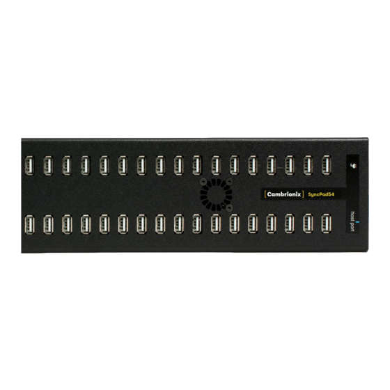
Page 3: Your Sp54 At A Glance
(up to 0.5A). The firmware can be up-dated to allow new charging profiles to be added, ensuring the SP54 can charge the latest devices. It is ready to charge out-of-the-box and to sync devices when attached to a host computer. -
Page 4: Safety
Indicates a potentially hazardous situation which, if not avoided, may result in moderate or minor (reversible) injury. Indicates a potentially hazardous situation which, if not avoided, may result in damage to the product and/ or its functions or of a property in its proximity. SP54 Page 3 of 21... -
Page 5: Safety Alert Symbol
Mandatory regulation 3.4.Product modification Cambrionix products are designed and manufactured to meet the requirements of UK and International safety regulations. Modifications to the product could affect safety and render the product non-compliant to relevant safety standards, which could result in injury or damage to the product. -
Page 6: Power Supply
Do not short circuit the Power Supply Unit (PSU) supplied with your product Do not disconnect the power cord while the product is being used Do not bend or pull the power cord with excessive force SP54 Page 5 of 21... -
Page 7: Storage And Installation
Do not place the power cord near heat sources Connect the plug to an earthed socket Damage to your Cambrionix product may occur Operate the product only in an environment where the ambient temperature is inside the operating temperature range... -
Page 8: Getting Started
LED will be illuminated. The hub is now ready to charge attached devices. 4.3.Connecting to Host Once the power is connected connect the SP54 to your host system using a USB 2.0 Type-B cable, this is provided with your hub. Using an incorrect host cable may result in the hub and all subsequent ports not being recognised by your host. - Page 9 You can raise a support ticket for more in depth support here www.cambrionix.atlassian.net/servicedesk/customer/portals You can also download any of our manuals and keep up to date at the link here www.cambrionix.com/product-user-manuals SP54 Page 8 of 21...
-
Page 10: Using Your Sp54
In this section you can find information information on how to use your hub in a charge only or a charge and sync application. You can also find information on managing your hub and changing port modes, connecting multiple hubs to one host and using Cambrionix Software. 5.1.Using without connecting to a host computer When the Hub is switched on and is not connected to a local host computer it is automatically configured to charge devices using its intelligent charging algorithm. - Page 11 Please note that USB specifications require a minimum 100 mA charge current to be delivered during data transfer. As indicated in above, if the attached device has a BC1.2 compliant CDP port, the device can draw up to 0.5A while transferring data. SP54 Page 10 of 21...
-
Page 12: Manage Ports & Your Sp54
5.4. Manage Ports & Your SP54 Each port on your SP54 can be managed either individually or all together. You can turn the ports off and on, change the port mode or change the charging profiles. This can be done either through LiveViewer or by connecting to the hub via the API. -
Page 13: Cambrionix Api
5.4.4 Cambrionix API Cambrionix API allows you to monitor and control each port in more detail and to integrate these functions into your own workflow processes. The API comprises a daemon that can be downloaded from www.cambrionix.com/products/api and installed on the host machine. Port information and control can be provided through the API using JavaScript Object Notation (JSON) Remote Procedure Calls (RPC) over TCP. -
Page 14: Firmware
To install the firmware onto the hub simply click the hub/ hubs connected that you want to update and then select the firmware version you want to upgrade to. Once selected press the update button at the top and the update will commence. SP54 Page 13 of 21... -
Page 15: Command Line Instructions (Cli)
Your Cambrionix Firmware may get corrupted Do not interrupt the Firmware update process Do not disconnect the power during the update process 5.4.7 Command Line Instructions (CLI) Command Line Instructions can also be used to control and monitor the functions of the hub and attached devices over a VCP (Virtual COM Port). - Page 16 < > Tab key Re-runs previous command Examples mode c 3 Set port 3 to charge mode mode o Turn off all ports state 2 Reveal state of port 2 state Reveal state of all ports SP54 Page 15 of 21...
-
Page 17: Cleaning Your Sp54
If there is a dirt/ spillage over a ventilation slot, external data/ power connector or product aperture, please remove power from the unit without touching the liquid and contact Cambrionix immediately Ensure that the product is switched off and the power cord is removed from the product. -
Page 18: Product Specifications
5% to 95% non-condensing Dimensions 430 x 86 x 28mm Weight 1.5kg 6.4.Additional Connections 2x5 Tag-connect header (not fitted) JTAG debug Connectors Samtec Connector 1x2 header for Fan Other I/O's 2x7 header for LED and other additional I/O's SP54 Page 17 of 21... -
Page 19: Power Supply
6.5.Power Supply Input Voltage 100-240VAC 4A @ 115VAC Input Current (Typical) 2A @ 230VAC Input Frequency 50-60Hz Input Connector Output Voltage Output Current Output Power (Max) 180W Output Connector 4-pin DIN SP54 Page 18 of 21... -
Page 20: Disposal
Directive, is marked as being put on the market after August 12, 2005, and should not be disposed of as unsorted municipal waste. Please utilize your local WEEE collection facilities in the disposition of this product and otherwise observe all applicable requirements. SP54 Page 19 of 21... -
Page 21: Compliance And Standards
8.Compliance and Standards CB Certificate CE Tested and marked FCC Part 15 Tested and marked Housed within a UL94-VO specification fire enclosure RoHS Compliant Independently safety tested by the Underwriters Laboratory (UL) under file #E346549 SP54 Page 20 of 21... - Page 22 This manual may make reference to trademarks, registered trademarks, and other protected names and /or symbols of third-party companies not related in any way to Cambrionix. Where they occur these references are for illustrative purposes only and do not represent an endorsement of a product or service by Cambrionix, or an endorsement of the product(s) to which this manual applies by the third-party company in question.
- Page 23 Cambrionix Ltd The Maurice Wilkes Building Cowley Road Cambridge CB4 0DS United Kingdom +44 (0) 1223 755 520 enquiries@cambrionix.com www.cambrionix.com 08/2021 © 2021 Cambrionix Ltd. All rights reserved.
Need help?
Do you have a question about the SP54 and is the answer not in the manual?
Questions and answers