
Related Manuals for Vega VEGAPULS 66 Foundation Fieldbus Standpipe version


Summary of Contents for Vega VEGAPULS 66 Foundation Fieldbus Standpipe version
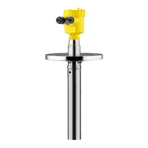
- Page 1 Quick setup guide Radar sensor for continuous level measurement of liquids VEGAPULS 66 Foundation Fieldbus Standpipe version Document ID: 47151...
-
Page 2: Table Of Contents
Contents Contents For your safety ......................... 3 Authorised personnel ....................... 3 Appropriate use ........................ 3 Warning about incorrect use ..................... 3 General safety instructions ....................3 EU conformity ........................4 NAMUR recommendations ....................4 Radio license for Europe ....................4 Radio license for USA ...................... -
Page 3: For Your Safety
1 For your safety For your safety Authorised personnel All operations described in this documentation must be carried out only by trained, qualified personnel authorised by the plant operator. During work on and with the device, the required personal protective equipment must always be worn. Appropriate use VEGAPULS 66 is a sensor for continuous level measurement. You can find detailed information about the area of application in chapter "... -
Page 4: Eu Conformity
1 For your safety EU conformity The device fulfils the legal requirements of the applicable EU direc- tives. By affixing the CE marking, we confirm the conformity of the instrument with these directives. The EU conformity declaration can be found on our homepage. Electromagnetic compatibility Instruments in four-wire or Ex-d-ia version are designed for use in an industrial environment. Nevertheless, electromagnetic interference from electrical conductors and radiated emissions must be taken into account, as is usual with class A instruments according to EN 61326- 1. If the instrument is used in a different environment, the electromag- netic compatibility to other instruments must be ensured by suitable... -
Page 5: Environmental Instructions
1 For your safety This device is approved for unrestricted use only inside closed, sta- tionary vessels made of metal, reinforced fiberglass or concrete. Changes or modifications not expressly approved by the manufac- turer could void the user’s authority to operate this equipment. Environmental instructions Protection of the environment is one of our most important duties. That is why we have introduced an environment management system with the goal of continuously improving company environmental pro- tection. The environment management system is certified according... -
Page 6: Product Description
Test certificate (PDF) - optional Move to " www.vega.com" and enter in the search field the serial number of your instrument. Alternatively, you can access the data via your smartphone: • Download the VEGA Tools app from the " Apple App Store" or the " Google Play Store" • Scan the DataMatrix code on the type label of the instrument or • Enter the serial number manually in the app... -
Page 7: Mounting
3 Mounting Mounting Mounting instructions Mounting 1. In case of turbulences or strong product movement in the vessel, long standpipe antennas should be fastened to the vessel wall. 2. The measurement is only possible inside the tube, the standpipe antenna must hence reach up to the requested min. level For further information see chapter "... -
Page 8: Connecting To The Bus System
4 Connecting to the bus system Connecting to the bus system Connecting Connection technology The voltage supply and signal output are connected via the spring- loaded terminals in the housing. Connection to the display and adjustment module or to the interface adapter is carried out via contact pins in the housing. -
Page 9: Wiring Plan, Single Chamber Housing
4 Connecting to the bus system 9. Tighten the compression nut of the cable entry gland. The seal ring must completely encircle the cable 10. Reinsert the display and adjustment module, if one was installed 11. Screw the housing lid back on The electrical connection is finished. -
Page 10: Set Up With The Display And Adjustment Module
5 Set up with the display and adjustment module Set up with the display and adjustment module Insert display and adjustment module The display and adjustment module can be inserted into the sensor and removed again at any time. You can choose any one of four differ- ent positions - each displaced by 90°. It is not necessary to interrupt the power supply. -
Page 11: Parameter Adjustment
5 Set up with the display and adjustment module Fig. 6: Installing the display and adjustment module in the double chamber housing In the electronics compartment In the connection compartment Note: If you intend to retrofit the instrument with a display and adjustment module for continuous measured value indication, a higher lid with an inspection glass is required. - Page 12 5 Set up with the display and adjustment module 100% Fig. 7: Parameterization example Min. level = max. measuring distance Max. level = min. measuring distance For this adjustment, the distance is entered when the vessel is full and nearly empty. If these values are not known, an adjustment with other distances, for example, 10 % and 90 % is also possible. Starting point for these distance specifications is always the seal surface of the thread or flange.
- Page 13 5 Set up with the display and adjustment module Note: A false signal suppression detects, marks and saves these false signals to ensure that they are ignored in the level measurement. This should be done with the lowest possible level so that all potential interfering reflections can be detected.
-
Page 14: Menu Overview
5 Set up with the display and adjustment module Menu overview Setup Menu item Parameter Default setting Measurement Sensor loop name Medium Liquid Water based Application Storage tank Vessel shape Vessel top Dished form Vessel bottom Dished form Vessel height/ Length of standpipe ex factory Measuring range Max. adjustment 0,000 m(d) - Page 15 5 Set up with the display and adjustment module Menu item Parameter Default setting Echo curve mem- Additional adjustments Menu item Default setting Instrument units Distance in m Temperature in °C Unit SV 2 Distance in m Probe length Length of standpipe ex factory False signal suppression - Linearisation Linear...
-
Page 16: Set Up With Smartphone/Tablet, Pc/Notebook Via Bluetooth
6 Set up with smartphone/tablet, PC/notebook via Bluetooth Set up with smartphone/tablet, PC/ notebook via Bluetooth Preparations Activate Bluetooth Make sure that the Bluetooth function of the display and adjustment module is activated. For this, the switch on the bottom side must be set to " On". Fig. -
Page 17: Connecting
Start the adjustment app and select the function "Setup". The smart- phone/tablet searches automatically for Bluetooth-capable instru- ments in the area. PC/Notebook Start PACTware and the VEGA project assistant. Select the device search via Bluetooth and start the search function. The device auto- matically searches for Bluetooth-capable devices in the vicinity. Connecting The message "... - Page 18 6 Set up with smartphone/tablet, PC/notebook via Bluetooth App view Fig. 9: Example of an app view - Setup sensor adjustment VEGAPULS 66 • Foundation Fieldbus...
-
Page 19: Supplement
7 Supplement Supplement Technical data Note for approved instruments The technical data in the respective safety instructions which are included in delivery are valid for approved instruments (e.g. with Ex approval). These data can differ from the data listed herein, for example regarding the process conditions or the voltage supply. All approval documents can be downloaded from our homepage. Electromechanical data - version IP66/IP67 and IP66/IP68 (0.2 bar) Options of the cable entry Ʋ... - Page 20 Subject to change without prior notice © VEGA Grieshaber KG, Schiltach/Germany 2021 VEGA Grieshaber KG Am Hohenstein 113 Phone +49 7836 50-0 77761 Schiltach E-mail: info.de@vega.com...
Need help?
Do you have a question about the VEGAPULS 66 Foundation Fieldbus Standpipe version and is the answer not in the manual?
Questions and answers