Vega VEGAPULS 61 Operating Instructions Manual
Ps60kp, ps60kk
Hide thumbs
Also See for VEGAPULS 61:
- Operating instructions manual (100 pages) ,
- Quick setup manual (24 pages) ,
- Safety manual (16 pages)
Table of Contents
Advertisement
Quick Links
Advertisement
Table of Contents

Related Manuals for Vega VEGAPULS 61


Summary of Contents for Vega VEGAPULS 61
-
Page 1: Operating Instructions
Operating Instructions VEGAPULS 61 Profibus PA Document ID: 28444... -
Page 2: Table Of Contents
6.10 Saving the parameter adjustment data ................40 Set up with PACTware and other adjustment programs Connect the PC ......................41 Parameter adjustment with PACTware ................42 Parameter adjustment with PDM ..................43 Saving the parameter adjustment data ................43 8 Maintenance and fault rectification VEGAPULS 61 • Profibus PA... - Page 3 You can find them listed in chapter "Product descrip- tion". Instructions manuals for accessories and replacement parts Tip: To ensure reliable setup and operation of your VEGAPULS 61, we of- fer accessories and replacement parts. The corresponding documen- tations are: •...
-
Page 4: About This Document
Action This arrow indicates a single action. Sequence of actions Numbers set in front indicate successive steps in a procedure. Battery disposal This symbol indicates special information about the disposal of bat- teries and accumulators. VEGAPULS 61 • Profibus PA... -
Page 5: For Your Safety
During work on and with the device the required personal protective equipment must always be worn. Appropriate use VEGAPULS 61 is a sensor for continuous level measurement. You can find detailed information about the area of application in chapter "Product description". -
Page 6: Ce Conformity
Modifications not expressly approved by VEGA will lead to expiry of the operating licence according to FCC/IC. VEGAPULS 61 is in conformity with part 15 of the FCC directives and fulfills the RSS-210 regulations. Note the corresponding regulations for operation: •... - Page 7 2 For your safety Please help us fulfill this obligation by observing the environmental instructions in this manual: • Chapter "Packaging, transport and storage" • Chapter "Disposal" VEGAPULS 61 • Profibus PA...
-
Page 8: Product Description
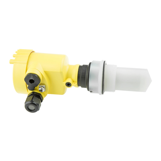
The electronics version influences the CE conformity, the factory set- ting for the medium selection and vessel form, the accuracy as well as the approvals of VEGAPULS 61. The differences are listed in the respective sections of this operating instructions manual. - Page 9 Fig. 1: VEGAPULS 61 - threaded version with encapsulated antenna system and plastic housing Housing cover with integrated PLICSCOM (optional) Housing with electronics 3 Process fitting with encapsulated antenna system Fig. 2: VEGAPULS 61 - threaded version with plastic horn antenna and plastic housing Housing cover with integrated PLICSCOM (optional) Housing with electronics 3 Process fitting with plastic horn antenna...
-
Page 10: Principle Of Operation
(also available as a download).A CD with the appropriate files can be ordered via e-mail under info@de.vega. com or by phone from one of the VEGA agencies under the order number "DRIVER.S". The backlight of the display and adjustment module is powered by the sensor. -
Page 11: Operation
The instrument can be adjusted with the following adjustment media: • With the display and adjustment module • with the suitable VEGA DTM in conjunction with an adjustment software according to the FDT/DTM standard, e.g. PACTware and • with the adjustment program PDM... -
Page 12: Mounting
Fig. 3: Measures against moisture ingress Measuring range The reference plane for the measuring range of the sensor depends on the antenna version. With encapsulated antenna system, the reference plane is the seal surface of the thread. VEGAPULS 61 • Profibus PA... - Page 13 The emitted radar impulses of VEGAPULS 61 are electromagnetic waves. The polarisation plane is the direction of the electrical share. Their position is marked on the instrument. Fig. 5: Position of the polarisation plane with VEGAPULS 61 with encapsulated antenna system Marking hole...
-
Page 14: Mounting Preparations, Mounting Strap
4 Mounting Fig. 6: Position of the polarisation plane with VEGAPULS 61 with plastic horn antenna Marking bars Suitability for the process Make sure that all parts of the instrument coming in direct contact conditions with the process, especially the sensor element, process seal and... - Page 15 Fig. 8: Vessel with conical bottom Inflowing medium Do not mount the instruments in or above the filling stream. Make sure that you detect the product surface, not the inflowing product. VEGAPULS 61 • Profibus PA...
- Page 16 Fig. 10: Recommended socket mounting If the reflective properties of the medium are good, you can mount VEGAPULS 61 on sockets which are higher than the length of the antenna. You will find recommended values for socket heights in the following illustration.
- Page 17 If large vessel installations such as struts or supports cause false echoes, these can be attenuated through supplementary measures. Small, inclined sheet metal baffles above the installations scatter the radar signals and prevent direct interfering reflections. Fig. 13: Cover flat, large-area profiles with deflectors VEGAPULS 61 • Profibus PA...
- Page 18 Make sure you provide the necessary upper vent hole in the surge pipe. The hole must be aligned so that it and the polarisation marking on the sensor are in the same plane (see illustration: "Pipe antenna system in a tank"). VEGAPULS 61 • Profibus PA...
- Page 19 Vent hole max. ø 5 mm (0.2 in) If possible, the antenna diameter of the sensor should correspond to the inner diameter of the tube. With VEGAPULS 61 this is approx. 40 mm (1.575 in). The sensor can be used with tube diameters be- tween 40 …...
- Page 20 4 Mounting 100% Fig. 16: VEGAPULS 61 in a bypass tube. The polarisation marking on the process fitting must be in one plane with the tube holes or the tube connection openings. Marking of the polarisation direction When the sensor is mounted on a bypass tube, the distance from VE- GAPULS 61 to the upper tube connection should be approx. 500 mm (19.69 in) or more.
- Page 21 Fig. 18: Flow measurement with Khafagi-Venturi flume: d = Min. distance to sen- sor; h = max. filling of the flume; B = tightest constriction in the flume max. Position sensor 2 Venturi flume Gauge measurement In general, the following points must be observed: • Installation of the sensor in a protected area • Installation vertical to the liquid surface VEGAPULS 61 • Profibus PA...
-
Page 22: Connecting To Power Supply
Voltage supply Power is supplied via a Profibus DP/PA segment coupler or a VEGA- LOG 571 EP input card. The power supply range can differ depending on the instrument version. -
Page 23: Connection Procedure
6. Lift the opening levers of the terminals with a screwdriver (see following illustration) 7. Insert the wire ends into the open terminals according to the wir- ing plan Fig. 19: Connection steps 6 and 7 VEGAPULS 61 • Profibus PA... -
Page 24: Wiring Plan, Single Chamber Housing
Fig. 20: Material versions, single chamber housing Plastic Aluminium Stainless steel, precision casting Stainless steel, electro-polished Filter element for air pressure compensation of all material versions. Blind plug with version IP 66/IP 68, 1 bar for Aluminium and stainless steel VEGAPULS 61 • Profibus PA... -
Page 25: Wiring Plan, Double Chamber Housing
Wiring plan Display I 2 C Fig. 22: Wiring plan, single chamber housing Voltage supply, signal output Wiring plan, double chamber housing The following illustrations apply to the non-Ex as well as to the Ex-ia version. VEGAPULS 61 • Profibus PA... - Page 26 Cable gland Electronics compartment Display I ² C 5 6 7 8 Fig. 24: Electronics compartment, double chamber housing Plug connector for VEGACONNECT (I²C interface) Internal connection cable to the connection compartment Terminals for VEGADIS 81 VEGAPULS 61 • Profibus PA...
-
Page 27: Wiring Plan, Double Chamber Housing Ex D
Wiring plan, double chamber housing Ex d Information: Instruments in Ex d version with hardware revision …- 01 or higher as well as with national approvals such as e.g. according to FM or CSA at a later date. VEGAPULS 61 • Profibus PA... - Page 28 Cable gland Electronics compartment Display I ² C 5 6 7 8 Fig. 28: Electronics compartment, double chamber housing Plug connector for VEGACONNECT (I²C interface) Internal connection cable to the connection compartment Terminals for VEGADIS 81 VEGAPULS 61 • Profibus PA...
-
Page 29: Wiring Plan - Version Ip 66/Ip 68, 1 Bar
Voltage supply, signal output Wiring plan - version IP 66/IP 68, 1 bar Wire assignment, con- nection cable Fig. 31: Wire assignment, connection cable brown (+) and blue (-) to power supply or to the processing system Shielding VEGAPULS 61 • Profibus PA... -
Page 30: Switch-On Phase
5 Connecting to power supply Switch-on phase Switch-on phase After VEGAPULS 61 is connected to voltage supply or after voltage recurrence, the instrument carries out a self-check for approx. 30 seconds. The following steps are carried out: • Internal check of the electronics •... -
Page 31: Set Up With The Display And Adjustment Module Plicscom
4. Screw housing cover with inspection window tightly back on Disassembly is carried out in reverse order. The display and adjustment module is powered by the sensor, an ad- ditional connection is not necessary. VEGAPULS 61 • Profibus PA... -
Page 32: Adjustment System
Adjustment system Fig. 33: Display and adjustment elements LC display Indication of the menu item number Adjustment keys • [OK] key: Key functions VEGAPULS 61 • Profibus PA... -
Page 33: Setup Steps
PACTware or DTM. Parameter adjustment As VEGAPULS 61 is a distance measuring instrument, the distance from the sensor to the product surface is measured. To have the real product level displayed, an allocation of the measured distance to the percentage height must be made. - Page 34 2. Enter the appropriate distance value in m (corresponding to the percentage value) for the full vessel. Keep in mind that the max. level must lie below the dead band. 3. Save the settings with [OK] and move to "Medium selection" with [->]. VEGAPULS 61 • Profibus PA...
- Page 35 "Liquid" or "Solid". Medium Liquid Information: With VEGAPULS 61 with electronics version "Increased safety", "Solid" is preset as factory setting. However, the instrument should be used preferably in liquids. In such cases, the medium selection should be set to "Liquid" during setup.
- Page 36 Enter the requested parameters via the appropriate keys, save your settings and jump to the next menu item with the [->] key. Caution: Note the following if the VEGAPULS 61 with corresponding approval is used as part of an overfill protection system according to WHG (Water Resources Act): If a linearisation curve is selected, the measuring signal is no longer necessarily linear to the filling height.
- Page 37 The menu item "Extended setting" offers the possibility to optimise Extended setting/Quick level change VEGAPULS 61 for applications in which the level changes very quickly. To do this, select the function "Quick level change > 1 m/min.". Extended setting quick level change > 1 m/min.
-
Page 38: Menu Schematic
Depending on the version and application, the highlighted menu windows may not always be available. Depending on the sensor type, see chapter "Technical data". Special parameters are parameters which are set customer-specifically on the service level with the adjustment software PACTware. VEGAPULS 61 • Profibus PA... -
Page 39: Basic Adjustment
Basic adjustment Display ▶ Diagnostics Service Info Peak value indicator Meas. reliability Curve selection Echo curve 15 dB ▼ Distance min.: 0.234 m(d) Sensor status Presentation of the echo Echo curve curve Distance max.: 5.385 m(d) VEGAPULS 61 • Profibus PA... -
Page 40: Saving The Parameter Adjustment Data
They are thus available for multiple use or service purposes. If VEGAPULS 61 is equipped with a display and adjustment module, the most important data can be read out of the sensor into the display and adjustment module. -
Page 41: Set Up With Pactware And Other Adjustment Programs
Fig. 35: Connection via VEGACONNECT externally I²C bus (com.) interface on the sensor I²C connection cable of VEGACONNECT VEGACONNECT USB cable to the PC Necessary components: • VEGAPULS 61 • PC with PACTware and suitable VEGA DTM VEGAPULS 61 • Profibus PA... -
Page 42: Parameter Adjustment With Pactware
Saving/printing the project as well as import/export functions are also part of the standard version. In the full version there is also an extended print function for complete project documentation as well as a save function for measured value VEGAPULS 61 • Profibus PA... -
Page 43: Parameter Adjustment With Pdm
It is recommended to document or save the parameter adjustment data. That way they are available for multiple use or service purposes. The VEGA DTM Collection and PACTware in the licensed, profession- al version provide suitable tools for systematic project documentation and storage. -
Page 44: Maintenance And Fault Rectification
24 hour service hotline Should these measures not be successful, please call in urgent cases the VEGA service hotline under the phone no. +49 1805 858550. The hotline is manned 7 days a week round-the-clock. Since we offer this service worldwide, the support is only available in the English language. -
Page 45: Exchanging The Electronics Module
"Set up" may have to be carried out again. Exchanging the electronics module If the electronics module is defective, it can be replaced by the user. In Ex applications, only instruments and electronics modules with ap- propriate Ex approval may be used. VEGAPULS 61 • Profibus PA... -
Page 46: Software Update
The electronics modules are adapted to the respective sensor and distinguish also in the signal output or power supply. Software update The software version of VEGAPULS 61 can be determined as follows: • on the type label of the electronics •... -
Page 47: How To Proceed If A Repair Is Needed
Attach the completed form and, if need be, also a safety data sheet outside on the packaging • Please contact the agency serving you to get the address for the return shipment. You can find the agency on our home page www.vega.com. VEGAPULS 61 • Profibus PA... -
Page 48: Dismount
Correct disposal avoids negative effects on humans and the environ- ment and ensures recycling of useful raw materials. Materials: see chapter "Technical data" If you have no way to dispose of the old instrument properly, please contact us concerning return and disposal. VEGAPULS 61 • Profibus PA... -
Page 49: Supplement
Sensor address 126 (default setting) Current value 10 mA, ±0.5 mA Damping (63 % of the input variable) 0 … 999 s, adjustable Met NAMUR recommendation NE 43 Resolution, digital > 1 mm (0.039 in) VEGAPULS 61 • Profibus PA... - Page 50 For products with low dielectric figure up to 50 cm (19.69 in). Corresponds to the range with 50 % of the emitted power Time to output the correct level (with max. 10 % deviation) after a sudden level change. Incl. non-linearity, hysteresis and non-repeatability. VEGAPULS 61 • Profibus PA...
- Page 51 1,0 m (3.280 ft) 10 m (32.80 ft) -15 mm (- 0.590 in) - 30 mm (- 1.180 in) Fig. 38: Deviation VEGAPULS 61 with encapsulated antenna system and increased sensitivity 10 mm (0.394 in) 5 mm (0.197 in) 0,5 m (1.6 ft) 20 m (65.60 ft)
- Page 52 -15 mm -30 mm Fig. 42: Accuracy VEGAPULS 61 with encapsulated antenna system and increased sensitivity Relating to the nominal measuring range, incl. hysteresis and repeatability. Time to output the correct level (with max. 10 % deviation) after a sudden level change.
- Page 53 30 mm 15 mm 1,0 m 20 m -15 mm -30 mm Fig. 44: Accuracy VEGAPULS 61 with plastic horn antenna and increased sensitivity Influence of the ambient temperature to the sensor electronics Average temperature coefficient of the 0.03 %/10 K zero signal (temperature error) Ambient conditions Ambient, storage and transport tempera- -40 …...
- Page 54 25 mm (0.984 in) with 25 °C (77 °F) Ʋ Diameter approx. 8 mm (0.315 in) Ʋ Colour - standard PE Black Depending on the version M12 x 1, according to DIN 43650, Harting, 7/8" FF. VEGAPULS 61 • Profibus PA...
- Page 55 IP 66/IP 68 (1 bar) NEMA 6P vestment casting (optionally available) Overvoltage category Protection class Approvals Instruments with approvals can have different technical specifications depending on the version. A suitable cable is the prerequisite for maintaining the protection rating. VEGAPULS 61 • Profibus PA...
-
Page 56: Profibus Pa
Each Profibus instrument gets an unambiguous ident number (ID number) from the Profibus user organisation (PNO). This ID number is also included in the name of the GSD file. For VEGAPULS 61 the ID number is 0 x 0772(hex) and the GSD file PS__0772.GSD. Optionally to this manufacturer- specific GSD file, PNO provides also a general so-called profile-specific GSD file. - Page 57 PA-Out Select additional cyclic value Fig. 45: VEGAPULS 61: Block diagram with AI (PA-OUT) value and additional cyclical value TB Transducer Block FB Function Block Module of the PA sensors For the cyclic data traffic, VEGAPULS 61 provides the following modules: •...
- Page 58 0 x 00 bad - non-specific Flash-Update active 0 x 04 bad - configuration error – Adjustment error – Configuration error with PV-Scale (PV-Span too small) – Unit irregularity – Error in the linearization table VEGAPULS 61 • Profibus PA...
- Page 59 (non-cascade) - active ad- Hi-Alarm visory alarm - high limited 0 x 8d good (non-cascade) - active crit- Lo-Lo-Alarm ical alarm - low limited 0 x 8e good (non-cascade) - active crit- Hi-Hi-Alarm ical alarm - high limited VEGAPULS 61 • Profibus PA...
-
Page 60: Dimensions
Fig. 50: Housing versions in protection IP 66/IP 68 (0.2 bar) - with integrated display and adjustment module the housing is 9 mm/0.35 in higher Plastic housing Aluminium housing Aluminium double chamber housing Stainless steel housing, electropolished Stainless steel housing - precision casting VEGAPULS 61 • Profibus PA... - Page 61 Aluminium housing Stainless steel housing - precision casting VEGAPULS 61, threaded version SW 50 mm (1.97") G1½A / 1½ NPT ø 39 mm (1.54") Fig. 52: VEGAPULS 61, threaded version G1½ A and 1½ NPT VEGAPULS 61 • Profibus PA...
- Page 62 ø 84 mm (3.31") Fig. 53: VEGAPULS 61, hygienic fitting Clamp 2" (ø64 mm), 2½" (ø77.5 mm), 3" (ø91 mm) according to DIN 32676, ISO 2852/316L Slotted nut according to DIN 11851 DN 50 and DN 80 Tuchenhagen Varivent DN 32 VEGAPULS 61 • Profibus PA...
- Page 63 125 mm (4.92") 2,5 mm (0.10") 75 mm (2.95") 107 mm (4.21") 9 mm (0.35") 115 mm (4.53") 12 mm (0.47") Fig. 54: VEGAPULS 61, version with mounting strap in 170 or 300 mm length VEGAPULS 61 • Profibus PA...
- Page 64 10 Supplement VEGAPULS 61, version with compression flange ø 107 mm ø 21 mm (4.21") (0.83") ø 75 mm (2.95") ø 115 mm (4.53") ø 156 mm (6.14") ø 200 mm (7.87") Fig. 55: VEGAPULS 61, compression flange DN 80/3"/JIS80 VEGAPULS 61 • Profibus PA...
- Page 65 10 Supplement VEGAPULS 61, version with adapter flange ø 75 mm (2.95") ø 98 mm (3.86") Fig. 56: VEGAPULS 61, adapter flange DN 100/DN 150 Adapter flange Seal VEGAPULS 61 • Profibus PA...
-
Page 66: Information
Les lignes de produits VEGA sont globalement protégées par des droits de propriété intellec- tuelle. Pour plus d'informations, on pourra se référer au site www.vega.com. VEGA lineas de productos están protegidas por los derechos en el campo de la propiedad indus- trial. Para mayor información revise la pagina web www.vega.com. - Page 67 Notes VEGAPULS 61 • Profibus PA...
-
Page 68: Information
Subject to change without prior notice © VEGA Grieshaber KG, Schiltach/Germany 2014 VEGA Grieshaber KG Phone +49 7836 50-0 Am Hohenstein 113...
Need help?
Do you have a question about the VEGAPULS 61 and is the answer not in the manual?
Questions and answers