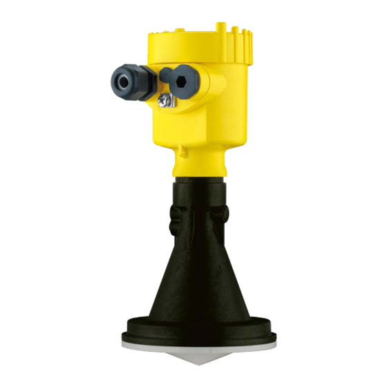
Vega VEGAPULS 61 Quick Setup Manual
Radar sensor for continuous level measurement of liquids
Hide thumbs
Also See for VEGAPULS 61:
- Operating instructions manual (100 pages) ,
- Quick setup manual (24 pages) ,
- Safety manual (16 pages)

Related Manuals for Vega VEGAPULS 61


Summary of Contents for Vega VEGAPULS 61
- Page 1 Quick setup guide Radar sensor for continuous level measurement of liquids VEGAPULS 61 Profibus PA Approval according to LPR radio standard Document ID: 47106...
-
Page 2: Table Of Contents
Operating Instructions Manual as well as the Safety Manual that comes with instruments with SIL qualification. These manuals are available on our homepage. Operating instructions VEGAPULS 61 - Profibus PA - Approval according to LPR radio standard; Document-ID 41715 Editing status of the quick setup guide: 2021-06-10... -
Page 3: For Your Safety
During work on and with the device, the required personal protective equipment must always be worn. Appropriate use VEGAPULS 61 is a sensor for continuous level measurement. You can find detailed information about the area of application in chapter " Product description". -
Page 4: Eu Conformity
The instrument must be stationary mounted and the antenna directed vertically downward • The mounting location must be at least 4 km away from radio astronomy stations, unless special permission was granted by the responsible national approval authority VEGAPULS 61 • Profibus PA... -
Page 5: Environmental Instructions
The environment management system is certified according to DIN EN ISO 14001. Please help us fulfil this obligation by observing the environmental instructions in this manual: • Chapter " Packaging, transport and storage" • Chapter " Disposal" VEGAPULS 61 • Profibus PA... -
Page 6: Product Description
Alternatively, you can access the data via your smartphone: • Download the VEGA Tools app from the " Apple App Store" or the " Google Play Store" • Scan the DataMatrix code on the type label of the instrument or •... -
Page 7: Mounting
Allen wrench size 4. There are two ways to screw the strap onto the sensor. Depending on the selected version, the sensors can be swivelled in the strap as follows: • Single chamber housing VEGAPULS 61 • Profibus PA... -
Page 8: Mounting Instructions
1. Distance from the vessel wall > 200 mm, the antenna should protrude > 10 mm into the vessel > 200 mm (7.87") Fig. 5: Distance of the antenna to the vessel wall/vessel ceiling 2. Note min. socket diameter depending on the socket length VEGAPULS 61 • Profibus PA... - Page 9 3 Mounting For further information see chapter " Mounting". VEGAPULS 61 • Profibus PA...
-
Page 10: Connecting To The Bus System
7. Check the hold of the wires in the terminals by lightly pulling on them 8. Connect the shielding to the internal ground terminal, connect the external ground terminal to potential equalisation VEGAPULS 61 • Profibus PA... -
Page 11: Wiring Plan, Single Chamber Housing
6 7 8 Fig. 8: Connection compartment - double chamber housing Voltage supply, signal output For display and adjustment module or interface adapter For external display and adjustment unit Ground terminal for connection of the cable screening VEGAPULS 61 • Profibus PA... - Page 12 4 Connecting to the bus system Information: Parallel use of an external display and adjustment unit and a display and adjustment module in the connection compartment is not sup- ported. VEGAPULS 61 • Profibus PA...
-
Page 13: Set Up With The Display And Adjustment Module
The display and adjustment module is powered by the sensor, an ad- ditional connection is not necessary. Fig. 9: Installing the display and adjustment module in the electronics compart- ment of the single chamber housing VEGAPULS 61 • Profibus PA... -
Page 14: Parameter Adjustment
3. Select in the menu item " Application" the vessel, the application and the vessel form, for example, storage tank. 4. Carry out the adjustment in the menu items " Min. adjustment" and " Max. adjustment". VEGAPULS 61 • Profibus PA... - Page 15 Additional settings - False The following circumstances cause interfering reflections and can signal suppression influence the measurement: • High mounting nozzles • Vessel internals such as struts VEGAPULS 61 • Profibus PA...
- Page 16 When selecting " Extend", the distance to the medium surface of the created false signal suppression is displayed. This value can now be changed and the false signal suppression can be extended to this range. VEGAPULS 61 • Profibus PA...
-
Page 17: Menu Overview
Filling height in % Backlight Switched on Diagnostics Menu item Parameter Default setting Device status Peak value indi- Distance cator Electronics tem- Temperature perature, further Measurement re- liability Simulation Percent Curve display Echo curve False signal sup- pression VEGAPULS 61 • Profibus PA... - Page 18 Actual date/Actual time Reset Copy instrument settings - Info Menu item Parameter Device name VEGAPULS 6. Instrument version Hardware and software version Date of manufacture Date Profibus ident number 4-digit, hexadecimal Instrument features Order-specific characteristics VEGAPULS 61 • Profibus PA...
-
Page 19: Set Up With Smartphone/Tablet, Pc/Notebook Via Bluetooth
1. In the adjustment menu, go to " Additional adjustments", " PIN" Note: The menu item " PIN" is only displayed if in the menu " Setup", " Lock/ Unlock adjustment" the adjustment is released. 2. Change sensor PIN VEGAPULS 61 • Profibus PA... -
Page 20: Connecting
Bluetooth-capable instru- ments in the area. PC/Notebook Start PACTware and the VEGA project assistant. Select the device search via Bluetooth and start the search function. The device auto- matically searches for Bluetooth-capable devices in the vicinity. - Page 21 6 Set up with smartphone/tablet, PC/notebook via Bluetooth App view Fig. 13: Example of an app view - Setup sensor adjustment VEGAPULS 61 • Profibus PA...
-
Page 22: Supplement
9 … 32 V DC Operating voltage - with Bluetooth 11.6 … 32 V DC switched on Operating voltage U with lighting 13.5 … 32 V DC switched on Number of sensors per DP/PA segment coupler, max. VEGAPULS 61 • Profibus PA... - Page 23 Notes VEGAPULS 61 • Profibus PA...
- Page 24 Subject to change without prior notice © VEGA Grieshaber KG, Schiltach/Germany 2021 VEGA Grieshaber KG Am Hohenstein 113 Phone +49 7836 50-0 77761 Schiltach E-mail: info.de@vega.com...
Need help?
Do you have a question about the VEGAPULS 61 and is the answer not in the manual?
Questions and answers