Vega VEGAPULS 61 Operating Instructions Manual
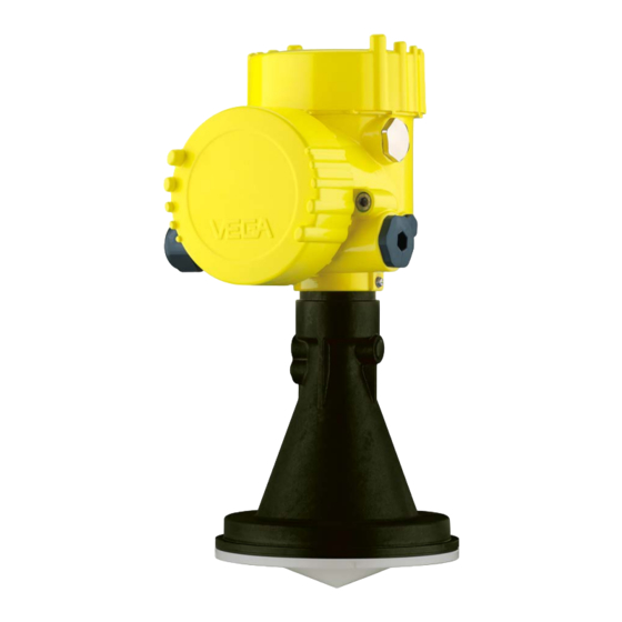
Radar sensor for continuous level
measurement of liquids
Hide thumbs
Also See for VEGAPULS 61:
- Operating instructions manual (96 pages) ,
- Quick setup manual (24 pages) ,
- Safety manual (16 pages)

Related Manuals for Vega VEGAPULS 61


Summary of Contents for Vega VEGAPULS 61
-
Page 1: Operating Instructions
Operating Instructions Radar sensor for continuous level measurement of liquids VEGAPULS 61 Modbus and Levelmaster protocol Approval according to LPR radio standard Document ID: 41717... -
Page 2: Table Of Contents
Saving the parameter adjustment data ................53 Setting up sensor and Modbus interface with PACTware Connect the PC ......................54 Parameter adjustment ....................55 Saving the parameter adjustment data ................57 Diagnosis, asset management and service Maintenance ........................58 VEGAPULS 61 • Modbus and Levelmaster protocol... - Page 3 10.8 Dimensions ........................89 Safety instructions for Ex areas Take note of the Ex specific safety instructions for Ex applications. These instructions are attached as documents to each instrument with Ex approval and are part of the operating instructions manual. Editing status: 2016-01-29 VEGAPULS 61 • Modbus and Levelmaster protocol...
-
Page 4: About This Document
This arrow indicates a single action. Sequence of actions Numbers set in front indicate successive steps in a procedure. Battery disposal This symbol indicates special information about the disposal of bat- teries and accumulators. VEGAPULS 61 • Modbus and Levelmaster protocol... -
Page 5: For Your Safety
During work on and with the device the required personal protective equipment must always be worn. Appropriate use VEGAPULS 61 is a sensor for continuous level measurement. You can find detailed information about the area of application in chapter "Product description". Operational reliability is ensured only if the instrument is properly used according to the specifications in the operating instructions manual as well as possible supplementary instructions. -
Page 6: Ce Conformity
Hungary implementing this radio standard at a later date. For operation outside of closed vessels, the following conditions must be fulfilled: • The installation must be carried out by trained qualified personnel • The instrument must be stationary mounted and the antenna directed vertically downward VEGAPULS 61 • Modbus and Levelmaster protocol... -
Page 7: Radio License For Usa/Canada
That is why we have introduced an environment management system with the goal of continuously improving company environmental pro- tection. The environment management system is certified according to DIN EN ISO 14001. Please help us fulfill this obligation by observing the environmental instructions in this manual: • Chapter "Packaging, transport and storage" • Chapter "Disposal" VEGAPULS 61 • Modbus and Levelmaster protocol... -
Page 8: Product Description
Alternatively, you can access the data via your smartphone: • Download the smartphone app "VEGA Tools" from the "Apple App Store" or the "Google Play Store" • Scan the Data Matrix code on the type label of the instrument or •... -
Page 9: Principle Of Operation
Principle of operation Application area The VEGAPULS 61 is a radar sensor for continuous level measure- ment of liquids under simple process conditions. The instrument is ideal also for all applications in the water and waste water industry. It is particularly suitable for level measurement in water treatment, in pump stations as well as storm water overflow tanks, for flow measurement in open flumes and for gauge measurement. -
Page 10: Accessories And Replacement Parts
You can find additional information in the supplementary instructions manual "Flanges according to DIN-EN-ASME-JIS". Electronics module Electronics module "VEGAPULS series 60" is a replacement part for radar sensors of VEGAPULS series 60. A different version is available for each type of signal output. You can find further information in the operating instructions "Elec- tronics module VEGAPULS series 60" (Document-ID 36801). VEGAPULS 61 • Modbus and Levelmaster protocol... - Page 11 Modbus" (Document-ID 41864). Antenna impedance cone The antenna impedance cone is a replacement part used for optimum transmission of microwaves and for sealing against the process. You find further information in the operating instructions "Antenna impedance cone VEGAPULS 62 and 68" (Document-ID 31381). VEGAPULS 61 • Modbus and Levelmaster protocol...
-
Page 12: Mounting
The free openings for the cable glands are therefore covered with red dust protection caps as transport protection. The dust protection caps do not provide sufficient protection against moisture. VEGAPULS 61 • Modbus and Levelmaster protocol... -
Page 13: Collar Or Adapter Flange
Max. torque, see chapter "Technical data". Required tools: Allen wrench size 4. There are two ways to screw the strap onto the sensor. Depending on the selected version, the sensors can be swivelled in the strap as follows: VEGAPULS 61 • Modbus and Levelmaster protocol... -
Page 14: Mounting Instructions
3. Tighten all screws with the torque stated in the technical data The emitted radar impulses of the radar sensor are electromagnetic Polarisation waves. The polarisation is the direction of the electrical wave compo- nent. By turning the instrument in the connection flange or mounting boss, the polarisation can be used to reduce the effects of false echoes. The position of the polarisation is marked on the process fitting of the instrument. VEGAPULS 61 • Modbus and Levelmaster protocol... - Page 15 In vessels with conical bottom it can be advantageous to mount the sensor in the center of the vessel, as measurement is then possible down to the lowest point of the vessel bottom. VEGAPULS 61 • Modbus and Levelmaster protocol...
- Page 16 Fig. 8: Mounting of the radar sensor with inflowing medium Socket with encapsulated The socket piece should be dimensioned in such a way that the an- antenna system tenna end protrudes at least 10 mm (0.4 in) out of the socket. VEGAPULS 61 • Modbus and Levelmaster protocol...
- Page 17 4 Mounting Fig. 9: Recommended socket mounting If the reflective properties of the medium are good, you can mount VEGAPULS 61 on sockets which are higher than the length of the antenna. You will find recommended values for socket heights in the following illustration. The socket end should be smooth and burr-free, if possible also rounded. After installation you must carry out a false echo storage.
- Page 18 Recommended values for socket heights are specified in the following illustration. You must carry out a false echo storage afterwards. The below charts specify the max. socket length h depending on the diameter d. Socket diameter d Socket length h 80 mm ≤ 300 mm VEGAPULS 61 • Modbus and Levelmaster protocol...
- Page 19 Fig. 14: Cover flat, large-area profiles with deflectors Agitators If there are agitators in the vessel, a false signal storage should be carried out with the agitators in motion. This ensures that the interfer- ing reflections from the agitators are saved with the blades in different positions. VEGAPULS 61 • Modbus and Levelmaster protocol...
-
Page 20: Measurement Setup - Pipes
Under these prerequisites, the measurement of products with low dielectric values (ε value ≤ 1.6) is possible. Note the following illustrations and instructions for measurement in a surge pipe. Information: Measurement in a surge pipe is not recommended for extremely adhesive products. VEGAPULS 61 • Modbus and Levelmaster protocol... - Page 21 4 Mounting Configuration surge pipe 100% Fig. 16: Configuration surge pipe VEGAPULS 61 Radar sensor Polarisation marking Thread or flange on the instrument Vent hole Holes Welding connection through U-profile Ball valve with complete opening Surge pipe end Reflector sheet 10 Fastening of the surge pipe...
- Page 22 • A false signal suppression with the installed sensor is recom- mended but not mandatory • The measurement through a ball valve with unrestricted channel is possible VEGAPULS 61 • Modbus and Levelmaster protocol...
- Page 23 • An extension via welding neck flanges or pipe collars is not recom- mended. Measurement in the An alternative to measurement in a surge pipe is measurement in a bypass tube bypass tube outside of the vessel. VEGAPULS 61 • Modbus and Levelmaster protocol...
- Page 24 • A false signal suppression with the installed sensor is recom- mended but not mandatory • The measurement through a ball valve with unrestricted channel is possible VEGAPULS 61 • Modbus and Levelmaster protocol...
-
Page 25: Measurement Setup - Flow
In general, the following points must be observed: • Install the sensor on the headwater side • Installation in the centre of the flume and vertical to the liquid surface • Distance to the overfall orifice • Distance of orifice opening above ground • Min. distance of the orifice opening to tailwater • Min. distance of the sensor to max. storage level VEGAPULS 61 • Modbus and Levelmaster protocol... - Page 26 Venturi flume In general, the following points must be observed: • Installation of the sensor at the inlet side • Installation in the centre of the flume and vertical to the liquid surface • Distance to the Venturi flume • Min. distance of the sensor to max. storage level VEGAPULS 61 • Modbus and Levelmaster protocol...
-
Page 27: Connecting To Power Supply And Bus System
Max. torque for all housings, see chapter "Technical data". Cable screening and In systems with potential equalisation, connect the cable screen grounding directly to ground potential at the power supply unit, in the connection VEGAPULS 61 • Modbus and Levelmaster protocol... -
Page 28: Connecting
4. Remove approx. 10 cm (4 in) of the cable mantle, strip approx. 1 cm (0.4 in) of insulation from the ends of the individual wires 5. Insert the cable into the sensor through the cable entry VEGAPULS 61 • Modbus and Levelmaster protocol... - Page 29 "Technical data - Electromechanical data" 7. Check the hold of the wires in the terminals by lightly pulling on them 8. Connect the screen to the internal ground terminal, connect the external ground terminal to potential equalisation VEGAPULS 61 • Modbus and Levelmaster protocol...
-
Page 30: Wiring Plan, Double Chamber Housing
Internal connection to the terminal compartment For display and adjustment module or interface adapter Information: The connection of an external display and adjustment unit is not pos- sible with this double chamber housing. VEGAPULS 61 • Modbus and Levelmaster protocol... -
Page 31: Double Chamber Housing With Disadapt
Double chamber housing with DISADAPT Electronics compartment Fig. 26: View to the electronics compartment with DISADAPT for connection of the external display and adjustment unit DISADAPT Internal plug connection Plug connector M12 x 1 VEGAPULS 61 • Modbus and Levelmaster protocol... -
Page 32: Switch-On Phase
Pin 3 Blue Pin 4 Black Switch-on phase After VEGAPULS 61 is connected to the bus system, the instrument carries out a self-test for approx. 30 seconds. The following steps are carried out: • Internal check of the electronics •... -
Page 33: Set Up The Sensor With The Display And Adjustment Module
The display and adjustment module is powered by the sensor, an ad- ditional connection is not necessary. Fig. 28: Insertion of the display and adjustment module Note: If you intend to retrofit the instrument with a display and adjustment module for continuous measured value indication, a higher lid with an inspection glass is required. VEGAPULS 61 • Modbus and Levelmaster protocol... -
Page 34: Adjustment System
1 s, the cursor moves continuously. When the [OK] and [ESC] keys are pressed simultaneously for more than 5 s, the display returns to the main menu. The menu language is then switched over to "English". VEGAPULS 61 • Modbus and Levelmaster protocol... -
Page 35: Measured Value Indication - Selection National Language
Display: Settings, e.g., for language, measured value display, lighting Diagnosis: Information, e.g. on instrument status, pointer, measure- ment certainty, simulation, echo curve Further settings: Instrument unit, false signal suppression, linearisa- tion curve, reset, date/time, reset, copy function VEGAPULS 61 • Modbus and Levelmaster protocol... - Page 36 Setup - Medium Each medium has different reflection properties. With liquids, further interfering factors are fluctuation product surface and foam genera- tion. With bulk solids, these are dust generation, material cone and additional echoes from the vessel wall. To adapt the sensor to these different measuring conditions, the selection "Liquid" or "Bulk solid" should be made in this menu item. VEGAPULS 61 • Modbus and Levelmaster protocol...
- Page 37 – Stable and reliable measured values through averaging – High accuracy – Short reaction time of the sensor not required Storage tank with product circulation: • Setup: large-volumed, upright cylindrical, spherical • Product speed: slow filling and emptying VEGAPULS 61 • Modbus and Levelmaster protocol...
- Page 38 – Sporadic false echoes are suppressed Dosing vessel: • Setup: all vessel sizes possible • Product speed: – Fast filling and emptying – Vessel is filled and emptied very often • Vessel: tight installation situation • Process/measurement conditions: – Condensation, buildup on the antenna – Foam generation VEGAPULS 61 • Modbus and Levelmaster protocol...
- Page 39 – Condensation on the plastic ceiling – In outdoor facilities, water and snow on vessel top possible • Properties, sensor: – False signals outside the vessel are not taken into consideration – False signal suppression recommended VEGAPULS 61 • Modbus and Levelmaster protocol...
- Page 40 – Sensor flooding possible • Properties, sensor: – Stable and reliable measured values through frequent averag- – Insensitive in the close range Demonstration: • Adjustment for all applications which are not typically level meas- urement VEGAPULS 61 • Modbus and Levelmaster protocol...
- Page 41 To perform the adjustment, enter the distance with full and empty ves- sel, see the following example: VEGAPULS 61 • Modbus and Levelmaster protocol...
- Page 42 2. Edit the percentage value with [OK] and set the cursor to the requested position with [->]. 3. Set the requested percentage value with [+] and save with [OK]. The cursor jumps now to the distance value. VEGAPULS 61 • Modbus and Levelmaster protocol...
- Page 43 5. Save settings with [OK] Setup - Damping To damp process-dependent measured value fluctuations, set an integration time of 0 … 999 s in this menu item. Depending on the sensor type, the factory setting is 0 s or 1 s. VEGAPULS 61 • Modbus and Levelmaster protocol...
- Page 44 With active PIN, adjustment via PACTware/DTM as well as other systems is also blocked. In delivery status, the PIN is "0000". Display - Language This menu item enables the setting of the requested national lan- guage. VEGAPULS 61 • Modbus and Levelmaster protocol...
- Page 45 In this menu item, the device status is displayed. status Diagnosis - Peak value The respective min. and max. measured value is saved in the sensor. The values are displayed in the menu item "Peak values". VEGAPULS 61 • Modbus and Levelmaster protocol...
- Page 46 5. Set the requested numerical value with [+] and [->]. 6. Push [OK] Note: During simulation, the simulated value is outputted as 4 … 20 mA cur- rent value and digital HART signal. VEGAPULS 61 • Modbus and Levelmaster protocol...
- Page 47 In this menu item you select the measured variable of the system and Additional adjustments - Device units the temperature unit. VEGAPULS 61 • Modbus and Levelmaster protocol...
- Page 48 Check the distance to the product surface, because if an incorrect (too large) value is entered, the existing level will be saved as a false signal. The level would then no longer be detectable in this area. VEGAPULS 61 • Modbus and Levelmaster protocol...
- Page 49 Additional settings - PIN Entering a 4-digit PIN protects the sensor data against unauthorized access and unintentional modification. In this menu item, the PIN is displayed or edited and changed. However, this menu item is only available if adjustment is enabled in the menu "Setup". VEGAPULS 61 • Modbus and Levelmaster protocol...
- Page 50 Peak values, measured value: Resetting of the measured min. and max. distances to the actual measured value. The following table shows the default values of the instrument. De- pending on the instrument version, not all menu items are available or some may be differently assigned: VEGAPULS 61 • Modbus and Levelmaster protocol...
- Page 51 Length of the standpipe Ex factory Linearisation Linear curve HART mode Standard Address 0 Additional adjustments - The sensor offers the HART modes standard and Multidrop. In this HART mode menu item you determine the HART modes and enter the address with Multidrop. VEGAPULS 61 • Modbus and Levelmaster protocol...
- Page 52 Info - Instrument version In this menu item, the hardware and software version of the sensor is displayed. The 4 … 20 mA signal of the HART sensor is switched off. The sensor consumes a constant current of 4 mA. The measuring signal is transmitted exclusively as digital HART signal. VEGAPULS 61 • Modbus and Levelmaster protocol...
-
Page 53: Saving The Parameter Adjustment Data
If it is necessary to exchange a sensor, the display and adjustment module is inserted into the replacement instrument and the data are likewise written into the sensor via the menu item "Copy sensor data". VEGAPULS 61 • Modbus and Levelmaster protocol... -
Page 54: Setting Up Sensor And Modbus Interface With Pactware
Interface adapter VEGACONNECT Sensor To the Modbus electron- Connection of the PC to the Modbus electronics is carried out via a USB cable. Scope of the parameter adjustment: • Sensor electronics • Modbus electronics VEGAPULS 61 • Modbus and Levelmaster protocol... -
Page 55: Parameter Adjustment
For parameter adjustment of the instrument via a Windows PC, the configuration software PACTware and a suitable instrument driver (DTM) according to FDT standard are required. The latest PACTware version as well as all available DTMs are compiled in a DTM Collec- VEGAPULS 61 • Modbus and Levelmaster protocol... - Page 56 The standard version is available as a download under www.vega.com/downloads and "Software". The full version is avail- able on CD from the agency serving you. VEGAPULS 61 • Modbus and Levelmaster protocol...
-
Page 57: Saving The Parameter Adjustment Data
7 Setting up sensor and Modbus interface with PACTware Saving the parameter adjustment data We recommend documenting or saving the parameter adjustment data via PACTware. That way the data are available for multiple use or service purposes. VEGAPULS 61 • Modbus and Levelmaster protocol... -
Page 58: Diagnosis, Asset Management And Service
Changes in the measure- ment conditions during operation or buildup on the sensor can thus be recognized. The echo curve of the setup is stored via: • PC with PACTware/DTM • Control system with EDD • Display and adjustment module VEGAPULS 61 • Modbus and Levelmaster protocol... -
Page 59: Asset Management Function
Plan in maintenance for the instrument because a failure is expected in the near future (e.g. due to buildup). This status message is inactive by default. It can be activated by the user via PACTware/DTM or EDD. VEGAPULS 61 • Modbus and Levelmaster protocol... - Page 60 – Send instrument for repair F125 – Temperature of the – Check ambient tem- Bit 7 electronics in the non- perature Impermissible electronics specified range – Isolate electronics temperature – Use instrument with higher temperature range VEGAPULS 61 • Modbus and Levelmaster protocol...
- Page 61 Overfilling – Check level in the vessel Maintenance The following table shows the error codes and text messages in the status message "Maintenance" and provides information on causes as well as corrective measures. VEGAPULS 61 • Modbus and Levelmaster protocol...
-
Page 62: Rectify Faults
PACTware and the suitable DTM. In many cases, the reasons can be determined in this way and faults rectified. Treatment of measure- The below tables show typical examples of application-related meas- ment errors with liquids urement errors with liquids. The measurement errors are differentiated according to the following: VEGAPULS 61 • Modbus and Levelmaster protocol... - Page 63 – Amplitude or position of a false – Determine the reason for the signal has changed (e.g. con- changed false signals, carry out densation, buildup); false signal false signal suppression, e.g. suppression no longer matches with condensation actual conditions VEGAPULS 61 • Modbus and Levelmaster protocol...
- Page 64 – Remove contamination on the sensor goes into overfill protec- time antenna tion mode. The max. level (0 m – Use a sensor with a more suit- distance) as well as the status able antenna message "Overfill protection" are outputted. VEGAPULS 61 • Modbus and Levelmaster protocol...
-
Page 65: Exchanging The Electronics Module
24 hour service hotline Should these measures not be successful, please call in urgent cases the VEGA service hotline under the phone no. +49 1805 858550. The hotline is also available outside normal working hours, seven days a week around the clock. -
Page 66: Software Update
Clean the instrument and pack it damage-proof • Attach the completed form and, if need be, also a safety data sheet outside on the packaging • Please contact the agency serving you to get the address for the return shipment. You can find the agency on our home page www.vega.com. VEGAPULS 61 • Modbus and Levelmaster protocol... -
Page 67: Dismount
Pass the instrument directly on to a spe- cialised recycling company and do not use the municipal collecting points. These may be used only for privately used products according to the WEEE directive. VEGAPULS 61 • Modbus and Levelmaster protocol... -
Page 68: Supplement
Clamp, slotted nut according to DIN 11851, Tuchenha- gen Varivent Weight depending on process fitting and 0.7 … 3.4 kg (1.543 … 7.496 lbs) housing material Torques Max. torques, threaded version Ʋ G1½ 7 Nm (5.163 lbf ft) VEGAPULS 61 • Modbus and Levelmaster protocol... - Page 69 Ʋ Physical layer Digital output signal according to standard EIA-485 Ʋ Bus specifications Modbus Application Protocol V1.1b3, Modbus over se- rial line V1.02 Ʋ Data protocols Modbus RTU, Modbus ASCII, Levelmaster Max. transmission rate 57.6 Kbit/s VEGAPULS 61 • Modbus and Levelmaster protocol...
- Page 70 Fig. 52: Deviation under reference conditions - plastic horn antenna Reference plane Antenna edge Recommended measuring range Repeatability ≤ ±1 mm Deviation with bulk solids The values depend to a great extent on the application. Binding specifications are thus not possible. VEGAPULS 61 • Modbus and Levelmaster protocol...
- Page 71 M20 x 1.5 or ½ NPT Time span after a sudden measuring distance change by max. 0.5 m in liquid applications, max 2 m with bulk solids applications, until the output signal has taken for the first time 90 % of the final value (IEC 61298-2). Outside the specified beam angle, the energy of the radar signal is reduced by 50 % (-3 dB) EIRP: Equivalent Isotropic Radiated Power VEGAPULS 61 • Modbus and Levelmaster protocol...
- Page 72 Depending on the electronics version via the HART, Profibus PA, Foundation Fieldbus or Modbus signal Range -40 … +85 °C (-40 … +185 °F) Resolution < 0.1 K Accuracy ±3 K Voltage supply Operating voltage 8 … 30 V DC VEGAPULS 61 • Modbus and Levelmaster protocol...
-
Page 73: Basics Modbus
Instruments with approvals can have different technical specifications depending on the version. For that reason the associated approval documents of these instruments have to be carefully noted. They are part of the delivery or can be downloaded under www.vega.com, "VEGA Tools" and "Instrument search" as well as in the download area. - Page 74 Fig. 53: Bus architecture Modbus Connection resistor Bus participant Voltage supply Protocol description The VEGAPULS 61 is suitable for connection to the following RTUs with Modbus RTU or ASCII protocol. Protocol ABB Totalflow Modbus RTU, ASCII Bristol ControlWaveMicro Modbus RTU, ASCII...
-
Page 75: Modbus Register
(4 bytes) according to IEEE 754 are transmitted with individually selectable order of the data bytes (byte transmission order). This "Byte transmission order" is determined in the parameter "Format Code". Hence the RTU knows the registers of the VEGAPULS 61 which must be contacted for the variables and status information. - Page 76 Primary Variable in Byte Order BACD (Middle Endian) 2204 DWord Secondary Variable in Byte Order BACD (Middle Endian) 2206 DWord Third Variable in Byte Order BACD (Middle Endian) 2208 DWord Quarternary Variable in Byte Order BACD (Middle Endian) VEGAPULS 61 • Modbus and Levelmaster protocol...
-
Page 77: Modbus Rtu Commands
FC4 Read Input Register With this command, any number (1-127) of input registers can be read out. The start register, from which the readout should start, and the number of registers are transmitted. VEGAPULS 61 • Modbus and Levelmaster protocol... - Page 78 With this function code different diagnostic functions can be triggered or diagnostic values read out. Request: Parameter Length Code/Data Function Code 1 Byte 0x08 Sub Function Code 2 Bytes Data N*2 Bytes Data Response: Parameter Length Code/Data Function Code 1 Byte 0x08 Sub Function Code 2 Bytes VEGAPULS 61 • Modbus and Levelmaster protocol...
- Page 79 With this function code, the Slave ID can be queried. Request: Parameter Length Code/Data Function Code 1 Byte 0x11 Response: Parameter Length Code/Data Function Code 1 Byte 0x11 Byte Number 1 Byte Slave ID 1 Byte Run Indicator Status 1 Byte VEGAPULS 61 • Modbus and Levelmaster protocol...
-
Page 80: Levelmaster Commands
List of Object value 1 Byte Depending on the Object ID 10.5 Levelmaster commands The VEGAPULS 61 is also suitable for connection to the following RTUs with Levelmaster protocol. The Levelmaster protocol is often called "Siemens" "Tank protocol". Protocol ABB Totalflow... - Page 81 If the temperature should be transmitted in the Levelmaster protocol, then TV must be set in the sensor to temperature. PV, SV and TV can be adjusted via the sensor DTM. Report Unit Number Request: Parameter Length Code/Data Report Unit Number 5 characters ASCII U**N? VEGAPULS 61 • Modbus and Levelmaster protocol...
- Page 82 = 81, even = 71 (default), odd = 71 Response: Parameter Length Code/Data Set Baud Rate 11 characters ASCII Example: U01B9600E71 Change instrument on address 1 to baudrate 9600, parity even, 7 data bits, 1 stop bit VEGAPULS 61 • Modbus and Levelmaster protocol...
-
Page 83: Error Codes
= milliseconds (50 up to 250), default = 127 ms Error codes Error Code Name EE-Error Error While Storing Data in EEPROM FR-Error Erorr in Frame (too short, too long, wrong data) LV-Error Value out of limits VEGAPULS 61 • Modbus and Levelmaster protocol... -
Page 84: Configuration Of Typical Modbus Hosts
10 Supplement 10.6 Configuration of typical Modbus hosts Fisher ROC 809 Wiring plan (Rx/Tx -) (Rx/Tx +) +30 Vdc Fig. 54: Connection of VEGAPULS 61 to RTU Fisher ROC 809 VEGAPULS 61 RTU Fisher ROC 809 Voltage supply Parameter Parameter Value Baud Rate 9600... - Page 85 10 Supplement ABB Total Flow Wiring plan Bus + Bus - VBAT Fig. 55: Connection of VEGAPULS 61 to RTU ABB Total Flow VEGAPULS 61 RTU ABB Total Flow Parameter Parameter Value Baud Rate 9600 Floating Point Format Code RTU Data Type...
- Page 86 10 Supplement Thermo Electron Autopilot Wiring plan Rx - +30 Vdc Fig. 56: Connection of VEGAPULS 61 to RTU Thermo Electron Autopilot VEGAPULS 61 RTU Thermo Electron Autopilot Voltage supply Parameter Parameter Value Baud Rate 9600 Floating Point Format Code...
- Page 87 3 TX- 4 GND 5 RXT 6 TXT 7 not used 8 not used +30 Vdc Fig. 57: Connection of VEGAPULS 61 to RTU Bristol ControlWave Micro VEGAPULS 61 RTU Bristol ControlWave Micro Voltage supply Parameter Parameter Value Baud Rate...
-
Page 88: Radio Astronomy Stations
10 Supplement ScadaPack Wiring plan COM Part 3 (C3) RS485 TXD- TXD+ +30 Vdc Fig. 58: Connection of VEGAPULS 61 to RTU ScadaPack VEGAPULS 61 RTU ScadaPack Voltage supply Parameter Parameter Value Baud Rate 9600 Floating Point Format Code RTU Data Type... -
Page 89: Dimensions
52°47'24" N 02°59'45" W Pickmere 53°17'18" N 02°26'38" W 10.8 Dimensions The following dimensional drawings represent only an extract of all possible versions. Detailed dimensional drawings can be downloaded at www.vega.com/downloads under "Drawings". VEGAPULS 61 • Modbus and Levelmaster protocol... - Page 90 (3.11") M16x1,5 M16x1,5 M20x1,5/ M20x1,5/ ½ NPT ½ NPT Fig. 59: Dimensions of housing - with integrated display and adjustment module the housing is 9 mm/0.35 inches higher Plastic housing Aluminium/Stainless steel housing VEGAPULS 61 • Modbus and Levelmaster protocol...
- Page 91 (4.92") 2,5 mm (0.10") 1.4301 PBT-GF30 75 mm (2.95") 9 mm 107 mm (0.35") (4.21") 115 mm (4.53") 12 mm (0.47") Fig. 60: VEGAPULS 61, mounting strap in 170 or 300 mm length VEGAPULS 61 • Modbus and Levelmaster protocol...
- Page 92 (4.21") (0.83") ø 75 mm (2.95") ø 115 mm (4.53") ø 156 mm (6.14") ø 200 mm (7.87") Fig. 61: VEGAPULS 61, compression flange suitable for DN 80 PN 16/ASME 3" 150lbs/JIS80 10K VEGAPULS 61 • Modbus and Levelmaster protocol...
- Page 93 ø 21 mm (4.21") (0.83") ø 75 mm (2.95") ø 156 mm (6.14") ø 200 mm (7.87") Fig. 62: VEGAPULS 61, compression flange with air rinsing suitable for DN 80 PN 16/ASME 3" 150lbs/JIS80 10K VEGAPULS 61 • Modbus and Levelmaster protocol...
- Page 94 10 Supplement VEGAPULS 61, version with adapter flange ø 75 mm (2.95") ø 98 mm (3.86") Fig. 63: VEGAPULS 61, adapter flange Adapter flange Seal VEGAPULS 61 • Modbus and Levelmaster protocol...
- Page 95 10 Supplement VEGAPULS 61, version with adapter flange and air rinsing ø 75 mm (2.95") ø 98 mm (3.86") Fig. 64: VEGAPULS 61, adapter flange Rinsing air connection Reflux valve Adapter flange VEGAPULS 61 • Modbus and Levelmaster protocol...
- Page 96 Les lignes de produits VEGA sont globalement protégées par des droits de propriété intellec- tuelle. Pour plus d'informations, on pourra se référer au site www.vega.com. VEGA lineas de productos están protegidas por los derechos en el campo de la propiedad indus- trial. Para mayor información revise la pagina web www.vega.com.
- Page 97 Foam generation 20 Functional principle 9 Vessel form 41 Vessel height 41 Vessel installations 19 HART mode 51 Inflowing medium 16 Installation position 15 Instrument version 52 Language 44 Linearisation curve 49 Lock adjustment 44 VEGAPULS 61 • Modbus and Levelmaster protocol...
- Page 98 Notes VEGAPULS 61 • Modbus and Levelmaster protocol...
- Page 99 Notes VEGAPULS 61 • Modbus and Levelmaster protocol...
- Page 100 Subject to change without prior notice © VEGA Grieshaber KG, Schiltach/Germany 2016 VEGA Grieshaber KG Phone +49 7836 50-0 Am Hohenstein 113...
Need help?
Do you have a question about the VEGAPULS 61 and is the answer not in the manual?
Questions and answers