Riello P200 T/N Installation, Use And Maintenance Instructions
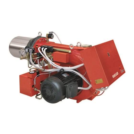
Heavy oil burners
Hide thumbs
Also See for P200 T/N:
- Manual (25 pages) ,
- Installation, use and maintenance instructions (40 pages)

Related Manuals for Riello P200 T/N


Summary of Contents for Riello P200 T/N
- Page 1 Installation, use and maintenance instructions Heavy oil burners CODE MODEL TYPE 3437785 P200 T/N 467 T80 3437786 P200 T/N 467 T80 2915832 (4) - 08/2012...
-
Page 3: Technical Data
TECHNICAL DATA Thermal power - Output 515 / 2280 kW - 45 / 200 kg/h (See sheet 3) Operation stage - 2 stage - 3 stage Oil with max. viscosity 50mm /s (7°E) at 50°C Fuel with kit: max. viscosity 500mm /s (65°E) at 50°C Pump 350 kg/h at 25 bar... - Page 4 Fig. 1 - Suction line 17 - Manometer - Return line 18 - Lamp - Air shutter opening motor 19 - Commutator - Pump pressure adjustment screw 20 - Low limit thermostat - Manometer plug (G 1/8) 21 - High limit thermostat - Vacuometer plug (G 1/2) 22 - Timer - Reset push-button of the motor overload relay...
- Page 5 COMBUSTION CHAMBER PRESSURE - MAXIMUM OUTPUT (Three nozzles in operation) Operation field: Limit Safety When the burner operates with only one or two nozzles, the pressurization conditions are improved and no problems arise. Boiler front plate drilling Combustion head projection For the combustion head projection carefully follow the boiler manufacturer indications.
- Page 6 OPERATION AND EFFICIENCY OF THE BURNER POWER AND OUTPUT MINIMUM MAXIMUM STAGE kg/h kg/h nozzle: ignition phase 1516 nozzle: intermediate phase 1140 2279 nozzle: operation phase POWER AND OUTPUT MINIMUM MAXIMUM STAGE kg/h kg/h nozzle: ignition phase 1516 nozzle: 1 stage of operation 1140 2279...
- Page 7 HEAVY OIL SUPPLY LINE RING SUPPLY LINE (for heavy oil with viscosity up to 50°E at 50°C) 1 - Tank (heated for heavy oil) 2 - Filter (with resistance for oil > 7°E at 50°C) 3 - Forwarding pump 4 - Control manometer 5 - Shutter valves (in couple) excluding the burner 6 - Burner (provided for Kit for heavy oil code no.
-
Page 8: Internal Wiring Diagram
INTERNAL WIRING DIAGRAM (carried out by the factory) D2618 LEGEND Fan motor contact maker Burner earth Commutator Electronic thermostat Resistor contact maker Maximal thermostat Photoresistance Minimal thermostat Burner terminal strip Timer Fan motor Lamps for 1 stage Control box Lamps for 2 stage Overload Lamps for 3... - Page 9 WIRING CONNECTORS TO THE TERMINAL BOARD (carried out by the installer) 2645 220V 380V A Ampere B Ampere C mm D mm Remote lock-out signal Limit control device system Optional switch on-off burner Safety control device system MB Burner terminal strip Load control system for 2 stage Reset push - button...
- Page 10 CHOICE: OF THE NOZZLES - OF THE PUMP PRESSURE - OF THE COMBUSTION HEAD ADJUSTMENT • First of all state the maximum output required with all three nozzles in operation. • On the base of the maximum output choose, from table A, three related nozzles. Nozzles: 60°...
- Page 11 Nozzles delivery Combustion head adjustment Pump pressure Maximum output Combustion head adjustment (set-point) Suggested pressure - Light oil: 25 bar - Heavy oil: 28 bar (transformation kit) Rated nozzles deliveries are listed on the table. A tolerance of ±5% concerns the real delivery against the rated one. The pump leaves the factory set at 25 bar.
- Page 12 AIR SHUTTERS ADJUSTMENTS The adjustment of the air shutters shall be set each time, with reference to the nozzles deliveries and the combustion chamber pressurization. Black lever has to anticipate the orange one Fig. 3 MV2 - Black lever ST3 - Red lever ST2 - Orange lever Fig.
- Page 13 SPRAY TEMPERATURE ADJUSTMENT Thermostat for adjustment - maximum value - minimum value Electronic adjustment thermostat by means of information relayed from a PT100 probe immersed in the oil in the delivery manifold, the thermostat adjusts spray temperature. (The correct conditions for fuel spray are shown in the temperature/viscosity graph below).
- Page 14 CYCLE OF THE BURNER START-UP Normal Lock-out because no ignition Thermostat Motor Ignition transformer Pre-purge stage valve stage valve stage valve Lock-out lamp D2848 Factory setting: 20 s. D3211 This time determines the heavy oil tempera- ture at ignition. It can be adjusted, accord- ing to the fuel’s viscosity, by the timer 22) (Fig.
-
Page 15: Burner Start-Up Cycle Diagnostics
BURNER START-UP CYCLE DIAGNOSTICS During start-up, indication is according to the followin table: COLOUR CODE TABLE Sequences Colour code Pre-purging Ignition phase Operation, flame ok Operating with weak flame signal Electrical supply lower than ~ 170V Lock-out Extraneous light Yellow Green Key: OPERATING FAULT DIAGNOSTICS... - Page 16 RIELLO S.p.A. I-37045 Legnago (VR) Tel.: +39.0442.630111 http:// www.riello.it http:// www.rielloburners.com Subject to modifications...
Need help?
Do you have a question about the P200 T/N and is the answer not in the manual?
Questions and answers