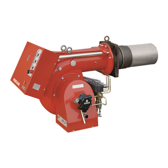
Riello P200 T/G Installation, Use And Maintenance Instructions
Light oil burners
Hide thumbs
Also See for P200 T/G:
- Installation, use and maintenance instructions (68 pages) ,
- Installation, use and maintenance instructions (56 pages) ,
- Installation, use and maintenance instructions (60 pages)

Related Manuals for Riello P200 T/G


Summary of Contents for Riello P200 T/G
- Page 1 Installation, use and maintenance instructions Light oil burners CODE MODEL TYPE 3477785 P200 T/G 477 T80 3477786 P200 T/G 477 T80 2915906 (3) - 11/2012...
-
Page 3: Electrical Data
TECHNICAL DATA Thermal power - Output 530 / 2370 kW - 45 / 200 kg/h (see page 2) Operation stage - 2 stage - 3 stage Fuel Light oil, max. viscosity at 20° C: 6 mm /s (1.5° E) ELECTRICAL DATA Motor IE1 Three-phase 220V +10% -10% ~ 60Hz without neutral Electrical supply... - Page 4 DIMENSIONS (mm) Boiler front plate Burner drilling * It is possible with a spacer upon request. OPERATION AND EFFICIENCY OF THE BURNER POWER AND OUTPUT STAGE MINIMUM MAXIMUM kg/h kg/h nozzle: ignition phase 1576 nozzle: intermediate phase 1186 2372 nozzle: operation phase POWER AND OUTPUT STAGE MINIMUM...
- Page 5 COMBUSTION CHAMBER PRESSURE - MAXIMUM OUTPUT (three nozzles in operation) Operation field in accordance with DIN 4787 When the burner operates with only one, or two nozzles, the pressurization conditions are improved and no prob- lems arise. DIMENSIONS OF THE TESTING COMBUSTION CHAMBER (in compliance with ISO 5063 - 1978) For the combustion head projection carefully follow the boiler manufacturer indications.
-
Page 6: Supply Line
SUPPLY LINE NOTICE Before placing the burner in operation, ensure that the return line is open. Any obstruction may damage the pump seal. Pump priming: Loose the tap from the vacuometer plug 5 (fig. 1) and wait for the flow of the fuel. L meters meters I.D. -
Page 7: Internal Wiring Diagram
INTERNAL WIRING DIAGRAM (carried out by the factory) 2567 KEY TO LAYOUT Fan motor contactor Wiring terminal board Commutator Fan motor Photocell Thermal relay stage hourcounter Ignition transformer stage hourcounter Burner ground (earth) connection Safety stage hourcounter solenoid valve stage lamp stage solenoid valve stage lamp stage solenoid valve... - Page 8 ELECTRICAL CONNECTIONS TO THE WIRING TERMINAL BLOCK (to be carried out by the installer) D2648 220V 380V F Ampere S mm KEY TO LAYOUT Remote lock - out signal Load limit remote control system Burner manual stop switch Safety load control system Wiring terminal board stage load control system Reset push - button...
- Page 9 CHOICE OF: NOZZLES - PUMP PRESSURE - COMBUSTION HEAD ADJUSTMENT • State, first of all, the maximum output required with all three nozzles in operation. • On the base of the maximum required output, choose-from table A or B - three related nozzles. Nozzles: 60°...
- Page 10 Nozzles delivery Combustion head adjustment Pump pressure Maximum output Combustion head adjustment (set-point) Rated nozzles delivery are shown in the table. The real nozzle delivery may vary from the rated one up to ± 5%, its detection is made by weighing the oil sprayed out from the nozzle inserted in a tube.
-
Page 11: Air Damper Adjustment
AIR DAMPER ADJUSTMENT The air dampers adjustment shall be set each time in relation with the nozzles delivery and the combustion chamber pressurization. Fig. 3 Fig. 2 stage hyd. jack stage air damper stage hyd. jack stage air damper stage hyd. jack stage air damper Fig. -
Page 12: Electric Panel
ELECTRIC PANEL nozzle hourcounter with operation signal nozzle hourcounter with operation signal nozzle hourcounter with operation signal Motor lock-out signal 4 position commutator Control box lock-out signal with re-set push-button Hourcounter Deducting the number of hours of 2 nozzle hourcounter from those indicated in the 1 nozzle hourcounter you could know how many hours the burner has been performing only at 1 stage;... - Page 13 BBURNER START-UP CYCLE Normal Lock-out because no ignition Thermostat Motor Ignition transformer Safety valve flame valve flame valve flame valve Lock-out lamp 2896 ALTERNATIVE START-UP CYCLES 1) If you desire the pre-ignition being present during the complete pre-purge phase (29,5 s) remove the bridge from the terminals 11 - 3 and put it on the terminals 11 - 7 of the control box.
-
Page 14: Burner Start-Up Cycle Diagnostics
BURNER START-UP CYCLE DIAGNOSTICS During start-up, indication is according to the followin table: COLOUR CODE TABLE Sequences Colour code Pre-purging Ignition phase Operation, flame ok Operating with weak flame signal Electrical supply lower than ~ 170V Lock-out Extraneous light Key: Yellow Green OPERATING FAULT DIAGNOSTICS... - Page 16 RIELLO S.p.A. I-37045 Legnago (VR) Tel.: +39.0442.630111 http:// www.riello.it http:// www.rielloburners.com Subject to modifications...
Need help?
Do you have a question about the P200 T/G and is the answer not in the manual?
Questions and answers