Riello P 140 T/G Installation, Use And Maintenance Instructions
Light oil burners
Hide thumbs
Also See for P 140 T/G:
- Installation, use and maintenance instructions (68 pages) ,
- Installation, use and maintenance instructions (17 pages) ,
- Installation, use and maintenance instructions (60 pages)
Table of Contents
Advertisement
Quick Links
Istruzioni per installazione, uso e manutenzione
Montage und Bedienungsanleitung
Instructions pour installation, utilisation et entretien
Installation, use and maintenance instructions
I
Bruciatori di gasolio
D
Öl-Gebläsebrenner
F
Brûleurs fioul
GB
Light oil burners
Funzionamento tristadio
Dreistufig
Three-stage operation
Fonctionnement à 3 allures
CODE
3476821 - 3476823
3476822 - 3476824
3477721 - 3477723
3477722 - 3477724
3478831 - 3478837
3478832 - 3478838
3478833 - 3478839
3478834 - 3478840
3478835 - 3478841
3478836 - 3478842
3479331 - 3479336
3479332 - 3479337
3479333 - 3479338
3479334 - 3479339
MODELLO - MODELL
MODELE - MODEL
P 140 T/G
P 140 T/G
P 200 T/G
P 200 T/G
P 300 T/G
P 300 T/G
P 300 T/G
P 300 T/G
P 300 T/G
P 300 T/G
P 450 T/G
P 450 T/G
P 450 T/G
P 450 T/G
TIPO - TYP
TYPE
476 M1
476 M1
477 M1
477 M1
478 M1
478 M1
478 M1
478 M1
478 M1
478 M1
479 M1
479 M1
479 M1
479 M1
2915890 (8) - 06/2012
Advertisement
Table of Contents

Related Manuals for Riello P 140 T/G


Summary of Contents for Riello P 140 T/G
- Page 1 Three-stage operation Fonctionnement à 3 allures MODELLO - MODELL TIPO - TYP CODE MODELE - MODEL TYPE 3476821 - 3476823 P 140 T/G 476 M1 3476822 - 3476824 P 140 T/G 476 M1 3477721 - 3477723 P 200 T/G 477 M1...
-
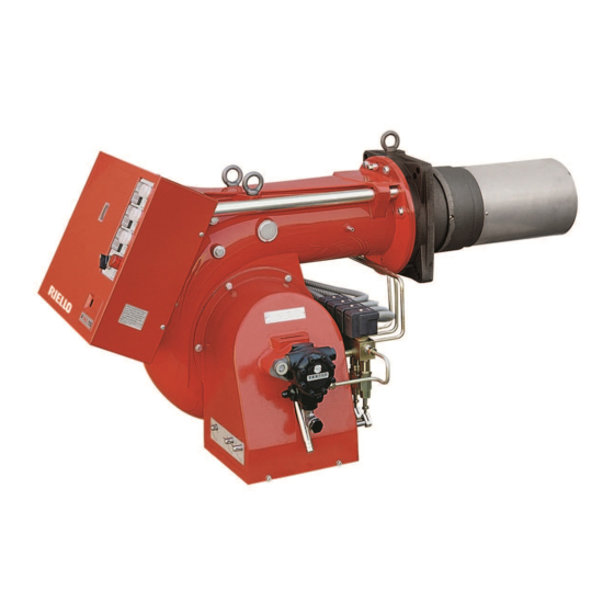
Page 2: Burner Description
7 - Terminal strip 4 - Manometer plug 8 - Control box reset push-button and lock-out lamp (G 1/8 for P 140 T/G and P 200 T/G; 9 - Fairleads G 1/4 for P 300 T/G and P 450 T/G) -
Page 3: Technical Data
2. TECHNICAL DATA 2.1 TECHNICAL DATA MODEL P 140 T/G P 200 T/G P 300 T/G P 450 T/G TYPE 476 M1 477 M1 478 M1 479 M1 THERMAL POWER 380÷1660 kW 557÷2370 kW 710÷3560 kW 890÷5340 kW OUTPUT 32÷140 kg/h 47÷200 kg/h... - Page 4 MOTOR IE2 MODEL P 140 T/G P 200 T/G P 300 T/G P 300 T/G CODE 3476821-3476823 3477721-3477723 3478831-3478837 3478835-3478841 3476822-3476824 3477722-3477724 3478832-3478838 3478836-3478842 3478833-3478839 3478834-3478840 ELECTRICAL SUPPLY 3N ~ 50 Hz 400 V 3 ~ 50 Hz 230 V MOTOR * 13.5 A / 230 V...
- Page 5 2.3 DIMENSIONS Boiler front-plate Burner drilling P 140 T/G 253*-363-473 P 200 T/G 281*-391-501 P 300 T/G 1000 314*-444-574 P 450 T/G 1070 346*-476-606 * It is possible with a spacer upon request...
- Page 6 2.4 OPERATION AND EFFICIENCY OF THE BURNER POWER AND OUTPUT STAGE MINIMUM MAXIMUM kg/h kg/h nozzle stage of operation 1103 nozzle stage of operation 1660 nozzle : 3 stage of operation POWER AND OUTPUT STAGE MINIMUM MAXIMUM kg/h kg/h nozzle stage of operation 1067 1576...
- Page 7 2.5 FIRING RATES (in accordance with DIN 4787) Combustion chambre pressure - Maximum output (three nozzles in operation) kg/h When the burner operates with only one, or two nozzles, the pressurizzation conditions are improved and no problems arise. DIMENSIONS OF THE TESTING COMBUSTION CHAMBRE (ISO 5063 - 1978) D - Boiler diameter (cm) P - Position of the boiler movable wall (m) For the combustion head projection carefully...
-
Page 8: Hydraulic Systems
3. HYDRAULIC SYSTEMS ATTENTION: Before placing the burner in operation, ensure that the return line is open. Any obstruction may demage the pump seal. P 140-200-300 T/G P 450 T/G L meters L meters meters øi øi øi øi 14 mm 16 mm 16 mm 18 mm... -
Page 9: Electrical System Factory-Set
4. ELECTRICAL SYSTEM 4.1 ELECTRICAL SYSTEM FACTORY-SET P 140 - 200 - 300 T/G DIRECT MOTOR STARTING KEY TO LAYOUTS (A) - (B) CMV - Motor contactor - Commutator - Photocell h1,2,3 - 1., 2., 3. stage hourconters L1,2,3 - 1., 2., 3. stage lamps - Lock-out motor lamp - Burner terminal strip - Fan motor... - Page 10 LAYOUT (A) - Electrical connection P 140-200-300 T/G P 140 - 200 - 300 T/G burners with direct motor starting DIRECT MOTOR STARTING D2568 Cables cross-section P 140 T/G P 200 T/G P 300 T/G 230 V 400 V 230 V...
- Page 11 Use nozzles with a 60° spray angle at the recommended pressure of 12 bar. For three-stage operation, up to: - 116 kg/h (P 140 T/G) - 170 kg/h (P 200 T/G) - 193 kg/h (P 300 T/G) and 2 nozzle are not equal to the 3 one.
- Page 12 P 300 T/G P 450 T/G NOZZLES 60° TOTAL NOZZLES 60° TOTAL DELIVERY DELIVERY PUMP 12 BAR PUMP 12 BAR kg/h kg/h 1° 2° 3° 1°+2°+3° 1° 2° 3° 1°+2°+3° 13,8 10,5 10,5 149,4 17,5 17,5 17,5 225,3 13,8 11,0 11,0 153,6 231,9...
-
Page 13: Air Damper Adjustment
6. AIR DAMPER ADJUSTMENT The air dampers adjustment shall be set each time in relation with the nozzles delivery and the combustion chamber pressurization. Fig. 3 Fig. 2 stage air damper stage hyd. jack stage air damper stage hyd. jack stage air damper stage hyd. -
Page 14: Electrodes Adjustment
8. ELECTRODES ADJUSTMENT 4 mm The measures must be respected. WARNING D11353 1 5 mm 9. BURNER OPERATION 9.1 BURNER START UP CYCLE Normal Lock-out because of no ignition Thermostat Motor Ignition transformer Safety valve flame valve flame valve flame valve Lock-out signal D2896 ALTERNATIVE START-UP CYCLES... -
Page 15: Burner Start-Up Cycle Diagnostics
10.BURNER START-UP CYCLE DIAGNOSTICS During start-up, indication is according to the followin table: COLOUR CODE TABLE Sequences Colour code Pre-purging Ignition phase Operation, flame ok Operating with weak flame signal Electrical supply lower than ~ 170V Lock-out Extraneous light Key: Yellow Green 11.OPERATING FAULT DIAGNOSTICS...
Need help?
Do you have a question about the P 140 T/G and is the answer not in the manual?
Questions and answers