Advertisement
Available languages
Available languages
Quick Links
Montage- und Betriebsanleitung
Montage- und Betriebsanleitung
DEHNSPANNFUTTER HYDRO MILL CHUCK
DEHNSPANNFUTTER HYDRO MILL CHUCK
HYDRAULIC CHUCK HYDRO MILL CHUCK
HYDRAULIC CHUCK HYDRO MILL CHUCK
| Installation an Operating Instructions
| Installation an Operating Instructions
DE
DE
DE
EN
EN
EN
Advertisement

Subscribe to Our Youtube Channel
Related Manuals for Mapal Hydro Mill Chuck


Summary of Contents for Mapal Hydro Mill Chuck
- Page 1 Montage- und Betriebsanleitung | Installation an Operating Instructions Montage- und Betriebsanleitung DEHNSPANNFUTTER HYDRO MILL CHUCK | Installation an Operating Instructions DEHNSPANNFUTTER HYDRO MILL CHUCK HYDRAULIC CHUCK HYDRO MILL CHUCK HYDRAULIC CHUCK HYDRO MILL CHUCK...
- Page 3 I I n n h h a a l l t t s s v v e e r r z z e e i i c c h h n n i i s s Z Z i i e e l l d d e e r r M M o o n n t t a a g g e e - - u u n n d d B B e e t t r r i i e e b b s s a a n n l l e e i i t t u u n n g g ................................................... . 4 4 K K o o n n t t a a k k t t .
- Page 4 Z Z i i e e l l d d e e r r M M o o n n t t a a g g e e - - u u n n d d B B e e t t r r i i e e b b s s a a n n l l e e i i t t u u n n g g Die vorliegende Montage- und Betriebsanleitung beschreibt die richtige Bedienung des Dehnspannfutters Hydro Mill Chuck mit axialer Werkzeuglängeneinstellung (nachfolgend als „Dehnspannfutter“...
- Page 5 • Bei langen, auskragenden und schweren Werkzeugen oder beim Einsatz von Verlängerungen muss die maximale Be- triebsdrehzahl gemäß den individuellen Gegebenheiten reduziert werden. • Das Abweichen der Vorschriften kann zu Verletzungen oder Beschädigungen von Maschinen und Zubehör führen, für die MAPAL keine Haftung übernimmt. Montage- und Betriebsanleitung Montage- und Betriebsanleitung...
- Page 6 • Das Dehnspannfutter darf nicht für die Werkstückspannung eingesetzt werden. • Das Dehnspannfutter darf nicht verändert und für andere Anwendungen erschlossen werden. • Zusätzliche Bohrungen, Gewinde und Anbauten dürfen nur nach schriftlicher Genehmigung durch MAPAL angebracht werden. • Im Falle von eigenmächtigen Veränderungen am Dehnspannfutter oder einer nicht bestimmungsgemäßen Verwendung des Dehnspannfutters, erlischt der Gewährleistungsanspruch gegenüber MAPAL.
- Page 7 Die Grenzbelastbarkeit der maschinenseitigen Schnittstelle nach z. B. VDMA 34181 beachten. Treten Unregelmäßigkeiten während der Bedienung auf, das Dehnspannfutter aus Sicherheitsgründen nicht mehr ein- setzen und es zur Überprüfung oder zur Reparatur an MAPAL senden. Montage- und Betriebsanleitung...
- Page 8 3 3 . . 5 5 . . 1 1 G G e e f f a a h h r r e e n n d d u u r r c c h h H H i i t t z z e e - - u u n n d d W W ä ä r r m m e e e e n n t t w w i i c c k k l l u u n n g g W W A A R R N N U U N N G G S S c c h h r r u u m m p p f f e e n n o o d d e e r r E E r r h h i i t t z z e e n n d d e e s s D D e e h h n n s s p p a a n n n n f f u u t t t t e e r r s s k k a a n n n n z z u u V V e e r r l l e e t t z z u u n n g g e e n n f f ü...
- Page 9 3 3 . . 5 5 . . 2 2 M M e e c c h h a a n n i i s s c c h h e e G G e e f f a a h h r r e e n n W W A A R R N N U U N N G G S S p p a a n n n n e e n n u u n n d d E E n n t t s s p p a a n n n n e e n n b b e e i i l l a a u u f f e e n n d d e e r r M M a a s s c c h h i i n n e e ! ! Durch das Spannen und Entspannen des Dehnspannfutters bei laufender Maschine können schwere Verletzungen des...
- Page 10 Einsatz kommen. Nicht die versiegelte Entlüftungsschraube beschädigen oder öffnen. Bei beschädigter Entlüftungsschraube das Dehnspannfutter aus Sicherheitsgründen nicht mehr einsetzen. Bei Beschädigung zur Überprüfung und Reparatur an MAPAL senden. Montage- und Betriebsanleitung Montage- und Betriebsanleitung...
- Page 11 H H I I N N W W E E I I S S V V e e r r s s c c h h l l e e i i ß ß d d u u r r c c h h m m a a s s c c h h i i n n e e l l l l e e n n S S c c h h r r a a u u b b e e n n d d r r e e h h e e r r b b e e i i m m S S p p a a n n n n e e n n d d e e r r S S p p a a n n n n s s c c h h r r a a u u b b e e ! ! Der Einsatz eines maschinellen Schraubendrehers beim Spannen der Spannschraube führt zu einem erhöhten Verschleiß...
- Page 12 Das Dehnspannfutter ist mit diesem Warnhinweis beschriftet. Warnhinweis auf dem Dehnspannfutter Position von Verbotssymbol und Warnhinweis auf dem Dehnspannfutter Montage- und Betriebsanleitung Montage- und Betriebsanleitung Installation and Operating Instructions Installation and Operating Instructions...
- Page 13 A A l l l l g g e e m m e e i i n n e e I I n n f f o o r r m m a a t t i i o o n n e e n n 4 4 .
- Page 14 L L e e g g e e n n d d e e Anschlagschraube zur axialen Werkzeuglängeneinstel- lung Sicht von unten auf das Dehnspannfutter 4 4 . . 2 2 B B e e s s c c h h r r i i f f t t u u n n g g d d e e r r B B e e t t ä ä t t i i g g u u n n g g s s e e l l e e m m e e n n t t e e Beschriftung zur Prüfung der Spannkraft Montage- und Betriebsanleitung Montage- und Betriebsanleitung...
- Page 15 L L e e g g e e n n d d e e + + Werkzeug spannen (im Uhrzeigersinn) - - Werkzeug lösen (gegen Uhrzeigersinn) Drehrichtungsangabe zum Lösen und Spannen des Werkzeugs 4 4 . . 3 3 B B e e n n ö ö t t i i g g t t e e W W e e r r k k z z e e u u g g e e , , H H i i l l f f s s - - u u n n d d B B e e t t r r i i e e b b s s s s t t o o f f f f e e •...
- Page 16 Die Grenzbelastbarkeit der maschinenseitigen Schnittstelle nach z. B. VDMA 34181 beachten. Treten Unregelmäßigkeiten während der Bedienung auf, das Dehnspannfutter aus Sicherheitsgründen nicht mehr ein- setzen und es zur Überprüfung oder zur Reparatur an MAPAL senden. • Allgemeine technische Daten •...
- Page 17 • Angabe zur Prüfung der Spannkraft (siehe Kapitel 4.2 und 4.5 • Richtwerte der maximalen Betriebsdrehzahlen von Dehnspannfutter mit HSK-Schnittstelle N N e e n n n n g g r r ö ö ß ß e e M M a a x x i i m m a a l l e e B B e e r r i i e e b b s s d d r r e e h h z z a a h h l l H H S S K K [ [ m m i i n n...
- Page 18 4 4 . . 5 5 P P r r ü ü f f u u n n g g d d e e r r S S p p a a n n n n k k r r a a f f t t Die Mindestumdrehungen werden auf dem Dehnspannfutter angegeben (siehe Kapitel 4.2 ) und stellen eine einfache und...
- Page 19 W W A A R R N N U U N N G G S S p p a a n n n n e e n n u u n n d d E E n n t t s s p p a a n n n n e e n n b b e e i i l l a a u u f f e e n n d d e e r r M M a a s s c c h h i i n n e e ! ! Durch das Spannen und Entspannen des Dehnspannfutters bei laufender Maschine können schwere Verletzungen des Bedieners verursacht werden.
- Page 20 Schieben Sie das Werkzeug mit dem Schaft voraus bis zur Anschlag- schraube in die Aufnahmebohrung des Dehnspannfutters. Werkzeug einschieben H H I I N N W W E E I I S S B B e e s s c c h h ä ä d d i i g g u u n n g g d d u u r r c c h h N N i i c c h h t t e e i i n n h h a a l l t t e e n n d d e e r r M M i i n n d d e e s s t t e e i i n n s s p p a a n n n n t t i i e e f f e e b b e e i i m m D D e e h h n n s s p p a a n n n n f f u u t t t t e e r r ! ! ...
- Page 21 I I N N F F O O R R M M A A T T I I O O N N Die Anschlagschraube zur axialen Werkzeuglängeneinstellung ist nicht gegen Herausfallen gesichert. Der angegebene Verstellbereich kann nicht überschritten werden. Die Betätigung der Anschlagschraube zur axialen Werkzeuglängen- einstellung ist beidseitig möglich.
- Page 22 I I N N F F O O R R M M A A T T I I O O N N Die Spannschraube ist gegen Herausfallen nicht gesichert! Achten Sie darauf, dass die Spannschraube schmutzfrei ist. Drehen Sie die Spannschraube mit Hilfe eines Innensechskantschlüssels Abb.
- Page 23 I I N N F F O O R R M M A A T T I I O O N N Die Spannschraube ist nicht gegen Herausfallen gesichert. Lösen Sie die Spannschraube mit U U m m d d r r e e h h u u n n g g e e n n mit Hilfe des pas- senden Innensechskantschlüssels mit Quergriff.
- Page 24 E E n n t t s s o o r r g g u u n n g g Nachdem das Gebrauchsende des Dehnspannfutters erreicht ist, muss das Dehnspannfutter einer umweltgerechten Entsor- gung zugeführt werden. Das Dehnspannfutter kann zur fachgerechten Entsorgung auch an MAPAL gesendet werden. Montage- und Betriebsanleitung...
- Page 26 T T a a b b l l e e o o f f c c o o n n t t e e n n t t s s P P u u r r p p o o s s e e o o f f t t h h e e i i n n s s t t a a l l l l a a t t i i o o n n a a n n d d o o p p e e r r a a t t i i n n g g i i n n s s t t r r u u c c t t i i o o n n s s ........................................2 2 7 7 C C o o n n t t a a c c t t .
- Page 27 P P u u r r p p o o s s e e o o f f t t h h e e i i n n s s t t a a l l l l a a t t i i o o n n a a n n d d o o p p e e r r a a t t i i n n g g i i n n s s t t r r u u c c t t i i o o n n s s These installation and operating instructions describe the correct operation of the hydraulic chuck Hydro Mill Chuck with axial tool length adjustment (hereinafter referred to as “hydraulic chuck”).
- Page 28 • By long, protruding and heavy tools or when an extension is used the max. rotational speed is to be reduced in accord- ance with the individual factures. • Failure to observe these instruction can result in injuries or damage to machines and accessories for which MAPAL as- sumes no liability.
- Page 29 Any modification to the hydraulic chuck or any unauthorised use will void all and any warranty claims against MAPAL. MAPAL expressly declines any liability for accidents or damage resulting from the use of damaged tools or damaged ma- chine parts. Wear parts are not covered by the warranty.
- Page 30 Observe the maximum load limit for the machine-side connection in accordance with e.g. VDMA 34181. If irregularities occur during operation, do not use the hydraulic chuck further for safety reasons and send it to MAPAL for inspection or repair. Montage- und Betriebsanleitung...
- Page 31 3 3 . . 5 5 . . 1 1 D D a a n n g g e e r r s s f f r r o o m m h h e e a a t t d d e e v v e e l l o o p p m m e e n n t t W W A A R R N N I I N N G G S S h h r r i i n n k k i i n n g g o o r r h h e e a a t t i i n n g g t t h h e e h h y y d d r r a a u u l l i i c c c c h h u u c c k k c c a a n n l l e e a a d d t t o o i i n n j j u u r r i i e e s s a a n n d d d d a a m m a a g g e e t t o o m m a a c c h h i i n n e e s s a a n n d d a a c c c c e e s s s s o o r r i i e e s s ! ! Shrinking or heating can cause the hydraulic chuck to become deformed or to burst explosively.
- Page 32 3 3 . . 5 5 . . 2 2 M M e e c c h h a a n n i i c c a a l l h h a a z z a a r r d d s s W W A A R R N N I I N N G G C C l l a a m m p p i i n n g g a a n n d d u u n n c c l l a a m m p p i i n n g g w w i i t t h h r r u u n n n n i i n n g g m m a a c c h h i i n n e e ! ! Clamping and unclamping the hydraulic chuck with the machine running may result in serious injuries to the operator.
- Page 33 Do not damage or loosen the sealed bleeder screw. If the bleeder screw is damaged, the hydraulic chuck must not be used for safety reasons. In the event of damage, send the hydraulic chuck to MAPAL for inspection and repair. Montage- und Betriebsanleitung...
- Page 34 N N O O T T I I C C E E W W e e a a r r d d u u e e t t o o u u s s e e o o f f a a p p o o w w e e r r s s c c r r e e w w d d r r i i v v e e r r f f o o r r t t i i g g h h t t e e n n i i n n g g t t h h e e c c l l a a m m p p i i n n g g s s c c r r e e w w ! ! Use of a power screwdriver for tightening the clamping screw will result in increased wear of the clamping set.
- Page 35 The hydraulic chuck bears this warning sign. Warning sign on the hydraulic chuck Position of prohibition symbol and warning sign on the hydraulic chuck Montage- und Betriebsanleitung Montage- und Betriebsanleitung Installation and Operating Instructions Installation and Operating Instructions...
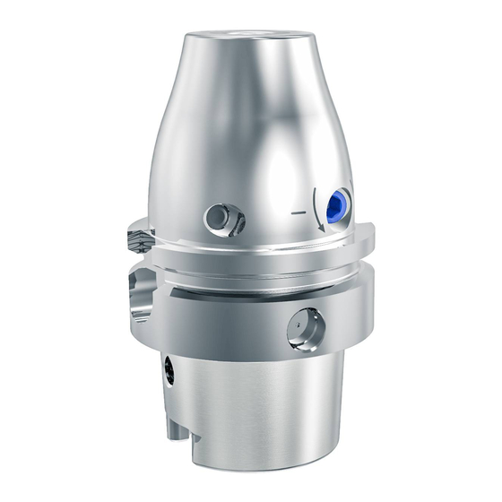
- Page 36 G G e e n n e e r r a a l l i i n n f f o o r r m m a a t t i i o o n n 4 4 . . 1 1 I I l l l l u u s s t t r r a a t t i i o o n n o o f f a a h h y y d d r r a a u u l l i i c c c c h h u u c c k k L L e e g g e e n n d d Location bore Clamping screw...
- Page 37 L L e e g g e e n n d d Stop screw for axial tool length adjustment View of the hydraulic chuck from below 4 4 . . 2 2 M M a a r r k k i i n n g g o o f f t t h h e e a a c c t t u u a a t t i i n n g g e e l l e e m m e e n n t t s s Marking for checking of the clamping force Montage- und Betriebsanleitung Montage- und Betriebsanleitung...
- Page 38 L L e e g g e e n n d d + + Clamp tool (in clockwise direction) - - Unclamp tool (in anticlockwise direction) Indication of the direction of rotation for clamping and unclamping the tool 4 4 . . 3 3 T T o o o o l l s s a a n n d d m m a a t t e e r r i i a a l l s s r r e e q q u u i i r r e e d d •...
- Page 39 Observe the maximum load limit for the machine-side connection in accordance with e.g. VDMA 34181. If irregularities occur during operation, do not use the hydraulic chuck further for safety reasons and send it to MAPAL for inspection or repair. • General technical data: •...
- Page 40 • Estimated rotational speed limits for hydraulic chuck with HSK connection N N o o m m i i n n a a l l s s i i z z e e M M a a x x . . r r o o t t a a t t i i o o n n a a l l s s p p e e e e d d [ [ r r p p m m ] ] H H S S K K 3 3 2 2...
- Page 41 4 4 . . 5 5 C C h h e e c c k k i i n n g g t t h h e e c c l l a a m m p p i i n n g g f f o o r r c c e e section 4.2 The minimum number of rotations are indicated on the hydraulic chuck (see ) and provide a simple and reliable...
- Page 42 W W A A R R N N I I N N G G C C l l a a m m p p i i n n g g a a n n d d u u n n c c l l a a m m p p i i n n g g w w i i t t h h r r u u n n n n i i n n g g m m a a c c h h i i n n e e ! ! Clamping and unclamping the hydraulic chuck with the machine running may result in serious injuries to the operator.
- Page 43 Push the tool, shank first, to the stop screw in the location bore in the hydraulic chuck. Inserting tool N N O O T T I I C C E E D D a a m m a a g g e e f f r r o o m m f f a a i i l l u u r r e e t t o o o o b b s s e e r r v v e e t t h h e e m m i i n n i i m m u u m m c c l l a a m m p p i i n n g g d d e e p p t t h h i i n n t t h h e e h h y y d d r r a a u u l l i i c c c c h h u u c c k k ! ! ...
- Page 44 I I N N F F O O R R M M A A T T I I O O N N The stop screw for axial tool length adjustment is not secured to prevent it from falling out. The specified adjusting range cannot be exceeded.
- Page 45 I I N N F F O O R R M M A A T T I I O O N N The clamping screw is not captive! Ensure that the clamping screw is clean. Turn the clamping screw u u p p t t o o t t h h e e s s t t o o p p using an hex-wrench with T- Fig.
- Page 46 I I N N F F O O R R M M A A T T I I O O N N The clamping screw is not captive. Loosen the clamping screw with 3 3 to 7 7 t t u u r r n n s s using an appropriate hex- wrench with T-handle.
- Page 47 Once the hydraulic chuck reaches the end of its service life, it must be disposed of with due care for the protection of the environment. The hydraulic chuck can also be sent to MAPAL for proper disposal. Montage- und Betriebsanleitung...
- Page 48 © MAPAL Präzisionswerkzeuge Dr. Kress KG Kein Teil dieser Anleitung darf in irgendeiner Form (Druck, Fotokopie, Mikrofilm oder einem anderen Verfahren) ohne schriftliche Zustimmung der Firma MAPAL Präzisionswerkzeuge Dr. Kress KG, Aalen, reproduziert oder unter Verwendung elektronischer Systeme verarbeitet werden.
Need help?
Do you have a question about the Hydro Mill Chuck and is the answer not in the manual?
Questions and answers