Advertisement
Available languages
Available languages
Quick Links
Advertisement

Related Manuals for Mapal WTE


Summary of Contents for Mapal WTE
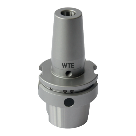
- Page 1 Montage- und Betriebsanleitung Installation and Operating Instructions Schrumpff utter Shrink chuck...
- Page 3 I I n n h h a a l l t t s s v v e e r r z z e e i i c c h h n n i i s s Z Z i i e e l l d d e e r r M M o o n n t t a a g g e e - - u u n n d d B B e e t t r r i i e e b b s s a a n n l l e e i i t t u u n n g g ................................................... . 4 4 K K o o n n t t a a k k t t .
- Page 4 Ausführung abweichen. K K o o n n t t a a k k t t WTE Präzisionstechnik GmbH Gewerbegebiet an der B95, .2a A A d d r r e e s s s s e e...
- Page 5 • Bei langen, auskragenden und schweren Werkzeugen oder beim Einsatz von Verlängerungen muss die maximale Be- triebsdrehzahl gemäß den individuellen Gegebenheiten reduziert werden. • Das Abweichen der Vorschriften kann zu Verletzungen oder Beschädigungen von Maschinen und Zubehör führen, für die WTE keine Haftung übernimmt. Montage- und Betriebsanleitung Montage- und Betriebsanleitung...
- Page 6 • Das Schrumpffutter darf nur vollständig abgekühlt eingesetzt werden. • Das Schrumpffutter und seine Komponenten dürfen nicht verändert und für andere Anwendungen erschlossen werden. • Zusätzliche Bohrungen, Gewinde und Anbauten dürfen nur nach schriftlicher Genehmigung durch WTE angebracht wer- den.
- Page 7 Die Grenzbelastbarkeit der maschinenseitigen Schnittstelle nach z. B. VDMA 34181 und des gewählten Werkzeuges beachten. Treten Unregelmäßigkeiten während der Bedienung auf, das Schrumpffutter aus Sicherheitsgründen nicht mehr ein- setzen und es zur Überprüfung oder zur Reparatur an WTE senden. Montage- und Betriebsanleitung Montage- und Betriebsanleitung...
- Page 8 3 3 . . 5 5 . . 1 1 G G e e f f a a h h r r e e n n d d u u r r c c h h H H i i t t z z e e - - u u n n d d W W ä ä r r m m e e e e n n t t w w i i c c k k l l u u n n g g W W A A R R N N U U N N G G V V e e r r b b r r e e n n n n u u n n g g s s g g e e f f a a h h r r b b e e i i m m S S c c h h r r u u m m p p f f v v o o r r g g a a n n g g ! ! Das erhitzte Schrumpffutter und heiße austretende Gase können schwere Verletzungen und Verbrennungen verursachen.
- Page 9 3 3 . . 5 5 . . 2 2 M M e e c c h h a a n n i i s s c c h h e e G G e e f f a a h h r r e e n n W W A A R R N N U U N N G G V V e e r r l l e e t t z z u u n n g g s s g g e e f f a a h h r r d d u u r r c c h h B B e e s s c c h h ä...
- Page 10 H H I I N N W W E E I I S S E E i i n n s s a a t t z z v v o o n n S S c c h h ä ä f f t t e e n n m m i i t t A A u u s s n n e e h h m m u u n n g g e e n n ! ! Der Einsatz von Schäften mit Form B und E (DIN 1835) oder Schäfte mit Form HB und HE (DIN 6535) kann zu ungenau- em Rundlauf und ungenauer Wuchtgüte des Gesamtsystems führen.
- Page 11 A A l l l l g g e e m m e e i i n n e e I I n n f f o o r r m m a a t t i i o o n n e e n n 4 4 .
- Page 12 L L e e g g e e n n d d e e Anschlagschraube zur axialen Werkzeuglängen- einstellung Längeneinstellschraube des Schrumpffutters L L e e g g e e n n d d e e Kühlmittelübergaberohr (optional) Blindschraube (optional) Kühlmittelübergaberohr und Blindschrauben Montage- und Betriebsanleitung Montage- und Betriebsanleitung...
- Page 13 L L e e g g e e n n d d e e Wiederverschließbare Kühlkanalbohrungen Anschlagschraube (optional) Wiederverschließbare Kühlkanalbohrungen 4 4 . . 2 2 B B e e n n ö ö t t i i g g t t e e W W e e r r k k z z e e u u g g e e , , H H i i l l f f s s - - u u n n d d B B e e t t r r i i e e b b s s s s t t o o f f f f e e •...
- Page 14 • Innensechskantschlüssel bzw. -Bit zum Einstellen der Anschlagschraube zur axialen Werkzeuglängeneinstellung S S p p a a n n n n d d u u r r c c h h m m e e s s s s e e r r S S p p a a n n n n d d u u r r c c h h m m e e s s s s e e r r S S c c h h l l ü...
- Page 15 Treten Unregelmäßigkeiten während der Bedienung auf, das Schrumpffutter aus Sicherheitsgründen nicht mehr ein- setzen und es zur Überprüfung oder zur Reparatur an WTE senden. • Allgemeine technische Daten: Werkstoff: Hitzebeständiger Werkzeugstahl für Warmarbeit 1 1 . . 6 6 0 0 0 0 N N / / m m m m ² ²...
- Page 16 Maximale Betriebsdrehzahl 5 5 0 0 . . 0 0 0 0 0 0 U U / / m m i i n n (Beachtung: Maximale Betriebsdrehzahl Schnittstelle; zusätzliche Feinwuch- tung empfohlen). Spannbar: Zylinderschäfte – Schaftdurchmessertoleranz h h 6 6 . Ein- und Ausschrumpfen von HM- und HSS-Werkzeugen bei Verwendung der entsprechenden Schrumpfgeräte.
- Page 17 • Technische Daten [m m m m ] Z Z u u l l . . ü ü b b e e r r t t r r a a g g b b a a r r e e s s D D r r e e h h m m o o m m e e n n t t b b e e i i S S p p a a n n n n d d u u r r c c h h m m e e s s s s e e r r M M i i n n d d e e s s t t e e i i n n s s p p a a n n n n t t i i e e f f e e S S c c h h a a f f t t K K l l e e i i n n s s t t m m a a ß...
- Page 18 • Technische Daten [Z Z o o l l l l ] Z Z u u l l . . ü ü b b e e r r t t r r a a g g b b a a r r e e s s D D r r e e h h m m o o m m e e n n t t b b e e i i S S p p a a n n n n d d u u r r c c h h m m e e s s s s e e r r M M i i n n d d e e s s t t e e i i n n s s p p a a n n n n t t i i e e f f e e S S c c h h a a f f t t K K l l e e i i n n s s t t m m a a ß...
- Page 19 B B e e d d i i e e n n u u n n g g d d e e s s S S c c h h r r u u m m p p f f f f u u t t t t e e r r s s 5 5 .
- Page 20 V V O O R R S S I I C C H H T T S S c c h h a a r r f f e e S S c c h h n n e e i i d d k k a a n n t t e e n n a a m m W W e e r r k k z z e e u u g g ! ! Scharfe Schneidkanten können Schnittverletzungen verursachen.
- Page 21 I I N N F F O O R R M M A A T T I I O O N N Für Handlungsschritt 3 wird ein Längenvoreinstelladapter empfoh- len. Die Anschlagschraube zur axialen Werkzeuglängeneinstellung ist nicht gegen Herausfallen gesichert. Stellen Sie das Schrumpffutter auf die Werkzeuglänge ein.
- Page 22 Erwärmen Sie das Schrumpffutter mit Hilfe eines geeigneten Schrumpf- geräts. Die Aufnahmebohrung für das Werkzeug weitet sich. Schrumpffutter mit Schrumpfgerät erwärmen Führen Sie den Werkzeugschaft bis zur Anschlagschraube in die Aufnah- mebohrung des Schrumpffutters ein. Werkzeug in Aufnahmebohrung einführen Montage- und Betriebsanleitung Montage- und Betriebsanleitung Installation and Operating Instructions...
- Page 23 Kühlen Sie das Schrumpffutter mit Werkzeug ab. E E R R G G E E B B N N I I S S Das Werkzeug ist nun vollständig eingeschrumpft und das Schrumpffutter kann eingesetzt werden. Schrumpffutter mit Werkzeug abkühlen 5 5 . . 2 2 A A u u s s s s c c h h r r u u m m p p f f e e n n e e i i n n e e s s W W e e r r k k z z e e u u g g s s W W A A R R N N U U N N G G V V e e r r b b r r e e n n n n u u n n g g s s g g e e f f a a h h r r b b e e i i m m S S c c h h r r u u m m p p f f v v o o r r g g a a n n g g ! ! Das erhitzte Schrumpffutter und heiße austretende Gase können schwere Verletzungen und Verbrennungen verursachen.
- Page 24 Erwärmen Sie das Schrumpffutter mit Hilfe eines geeigneten Schrumpf- geräts. Die Aufnahmebohrung für das Werkzeug weitet sich. Entnehmen Sie das Werkzeug aus dem Schrumpffutter. Lassen Sie das Schrumpffutter und das Werkzeug abkühlen. E E R R G G E E B B N N I I S S Das Werkzeug ist nun ausgeschrumpft und befindet sich nicht mehr im Schrumpffutter.
- Page 25 5 5 . . 3 3 K K ü ü h h l l m m i i t t t t e e l l ü ü b b e e r r g g a a b b e e r r o o h h r r d d u u r r c c h h B B l l i i n n d d s s c c h h r r a a u u b b e e e e r r s s e e t t z z e e n n Das optionale Kühlmittelübergaberohr kann bei Bedarf durch eine Blindschraube ersetzt werden.
- Page 26 5 5 . . 4 4 K K ü ü h h l l k k a a n n a a l l b b o o h h r r u u n n g g e e n n v v e e r r s s c c h h l l i i e e ß ß e e n n Die Kühlkanalbohrungen können mit separat erhältlichen Anschlagschrauben verschlossen werden.
- Page 27 ändern. Die Gewindestifte (mit Schraubensicherung gesichert) dichten dann jeweils die Bohrung zur alterna- tiven Kühlmittelzufuhr ab. Bei der Umstellung steht Ihnen auch der WTE Kundenservice zur Verfügung. 5 5 . . 5 5 . . 1 1 G G r r u u n n d d e e i i n n s s t t e e l l l l u u n n g g F F o o r r m m A A D D b b z z w w . . J J D D n n a a c c h h D D I I N N I I S S O O 7 7 3 3 8 8 8 8 Falls keine andere Bestellung vorliegt, werden die Werkzeughal- ter in F F o o r r m m A A D D ausgeliefert.
- Page 28 5 5 . . 5 5 . . 2 2 N N a a c c h h F F o o r r m m A A F F b b z z w w . . J J F F u u m m s s t t e e l l l l e e n n Umstellung von der Grundeinstellung nach Kühlmittelzuführung F F o o r r m m A A F F .
- Page 29 Entfernen Sie die Klebstoffreste an den Gewindestiften und Gewindeboh- rungen. Schrauben Sie in den abgekühlten Werkzeughalter an „Pos. 2“ die Ge- windestifte mit Schraubensicherung (Klebstoff) mittelfest ein (siehe Abb. 15: Kühlmittelzuführung F F o o r r m m A A F F / / J J F F Entfernen Sie eventuelle Klebstoffreste.
- Page 30 5 5 . . 5 5 . . 3 3 N N a a c c h h F F o o r r m m A A D D b b z z w w . . J J D D u u m m s s t t e e l l l l e e n n Umstellung der Kühlmittelzuführung von der Form AF nach Form AD.
- Page 31 Wuchtgewindebohrungen zur Verfügung. I I N N F F O O R R M M A A T T I I O O N N Bei Fragen zum Feinwuchten des Schrumpffutters wenden Sie sich bitte an den WTE Service. Montage- und Betriebsanleitung...
- Page 32 E E n n t t s s o o r r g g u u n n g g Nachdem das Gebrauchsende des Schrumpffutters erreicht ist, muss das Schrumpffutter einer umweltgerechten Entsorgung zugeführt werden. Das Schrumpffutter kann zur fachgerechten Entsorgung auch an WTE gesendet werden. Montage- und Betriebsanleitung...
- Page 33 T T a a b b l l e e o o f f c c o o n n t t e e n n t t s s P P u u r r p p o o s s e e o o f f t t h h e e I I n n s s t t a a l l l l a a t t i i o o n n a a n n d d O O p p e e r r a a t t i i n n g g I I n n s s t t r r u u c c t t i i o o n n s s ........................................3 3 4 4 C C o o n n t t a a c c t t .
- Page 34 C C o o n n t t a a c c t t WTE Präzisionstechnik GmbH Gewerbegebiet an der B95, Nr.2a A A d d d d r r e e s s s s...
- Page 35 • By long, protruding and heavy tools or when an extension is used the max. operating speed is to be reduced in accord- ance with the individual factures. • Failure to observe these instruction can result in injuries or damage to machines and accessories for which WTE assumes no liability.
- Page 36 The shrink chuck including all its components and accessories must not be modified or used for non-authorised applica- tions. Any modification to the shrink chuck or any unauthorised use will void all and any warranty claims against WTE. WTE expressly declines any liability for accidents or damage resulting from the use of damaged tools or damaged machine parts.
- Page 37 Observe the maximum load limit for the machine-side connection in accordance with e.g. VDMA 34181 and the selected tool. If irregularities occur during operation, do not use the shrink chuck further for safety reasons and send it to WTE for inspection or repair.
- Page 38 W W A A R R N N I I N N G G R R i i s s k k o o f f i i n n j j u u r r y y d d u u e e t t o o e e x x p p l l o o s s i i o o n n o o r r m m a a t t e e r r i i a a l l s s s s h h o o o o t t i i n n g g o o u u t t o o f f t t h h e e s s h h r r i i n n k k c c h h u u c c k k d d u u r r i i n n g g t t h h e e s s h h r r i i n n k k i i n n g g p p r r o o c c e e s s s s ! ! When heating during the shrinking process, closed liquid-filled areas, such as cooling channel bores, can lead to the ex- plosion of the shrink chuck or to the loosening of the shank from the location bore.
- Page 39 N N O O T T E E T T o o o o l l l l e e n n g g t t h h a a d d j j u u s s t t m m e e n n t t w w i i t t h h t t h h e e t t o o o o l l c c l l a a m m p p e e d d ! ! Performing an axial tool length adjustment while the tool is completely clamped will result in damage to the shrink chuck.
- Page 40 G G e e n n e e r r a a l l i i n n f f o o r r m m a a t t i i o o n n 4 4 . . 1 1 R R e e p p r r e e s s e e n n t t a a t t i i o o n n o o f f a a s s h h r r i i n n k k c c h h u u c c k k K K e e y y Location bore...
- Page 41 K K e e y y Stop screw for axial tool length adjustment Length adjustment screw of the shrink chuck K K e e y y Coolant delivery tube (optional) Blanking plug (optional) Coolant delivery tube and blanking plugs Montage- und Betriebsanleitung Montage- und Betriebsanleitung Installation and Operating Instructions Installation and Operating Instructions...
- Page 42 K K e e y y Resealable cooling channel bores Stop screw (optional) Resealable cooling channel bores 4 4 . . 2 2 T T o o o o l l s s a a n n d d m m a a t t e e r r i i a a l l s s r r e e q q u u i i r r e e d d •...
- Page 43 • Hex-wrench or bit for adjusting the stop screw for axial tool length adjustment C C l l a a m m p p i i n n g g d d i i a a m m e e t t e e r r C C l l a a m m p p i i n n g g d d i i a a m m e e t t e e r r W W r r e e n n c c h h s s i i z z e e S S W W C C l l a a m m p p i i n n g g s s c c r r e e w w s s i i z z e e...
- Page 44 Nach dem Erwärmen warten, bis der Gewindestiftbereich abgekühlt ist. selected tool. If irregularities occur during operation, do not use the shrink chuck further for safety reasons and send it to WTE for inspection or repair. Erwärmen Sie die Gewindestifte bzw. den Gewindestiftbereich, bis sich die •...
- Page 45 Suitable for clamping: Cylindrical shanks – shank diameter tolerance h h 6 6 . Shrinking and unshrinking carbide and HSS tools on the usage of corresponding shrink units. • Indicative values for operating speed limits for shrink chucks with HSK connection N N o o m m i i n n a a l l s s i i z z e e M M a a x x .
- Page 46 • Technical data [m m m m ] P P e e r r m m i i s s s s i i b b l l e e t t r r a a n n s s f f e e r r r r a a b b l l e e t t o o r r q q u u e e f f o o r r s s h h a a n n k k C C l l a a m m p p i i n n g g d d i i a a m m e e t t e e r r M M i i n n i i m m u u m m c c l l a a m m p p i i n n g g d d e e p p t t h h h h 6 6 m m i i n n i i m m u u m m s s i i z z e e...
- Page 47 • Technical data [i i n n c c h h ] P P e e r r m m i i s s s s i i b b l l e e t t r r a a n n s s f f e e r r r r a a b b l l e e t t o o r r q q u u e e f f o o r r s s h h a a n n k k C C l l a a m m p p i i n n g g d d i i a a m m e e t t e e r r M M i i n n i i m m u u m m c c l l a a m m p p i i n n g g d d e e p p t t h h h h 6 6 m m i i n n i i m m u u m m s s i i z z e e...
- Page 48 O O p p e e r r a a t t i i n n g g t t h h e e s s h h r r i i n n k k c c h h u u c c k k 5 5 .
- Page 49 C C A A U U T T I I O O N N S S h h a a r r p p c c u u t t t t i i n n g g e e d d g g e e s s o o n n t t h h e e t t o o o o l l ! ! Sharp cutting edges may cause cutting injuries.
- Page 50 I I N N F F O O R R M M A A T T I I O O N N For step 3, a length pre-adjuster adapter is recommended. The stop screw for axial tool length adjustment is not secured to prevent it from falling out.
- Page 51 Heat the shrink chuck using a suitable shrink unit. The location bore for the tool expands. Heat the shrink chuck with shrink unit Insert the tool shank into the location bore to the stop screw of the shrink chuck. Insert tool into the location bore Montage- und Betriebsanleitung Montage- und Betriebsanleitung...
- Page 52 Cool the shrink chuck with tool. R R E E S S U U L L T T The tool is now fully shrunk and the shrink chuck and can be used. Cool the shrink chuck with tool 5 5 . . 2 2 U U n n s s h h r r i i n n k k i i n n g g a a t t o o o o l l W W A A R R N N I I N N G G R R i i s s k k o o f f b b u u r r n n s s d d u u r r i i n n g g t t h h e e s s h h r r i i n n k k i i n n g g p p r r o o c c e e s s s s ! !
- Page 53 Heat the shrink chuck using a suitable shrink unit. The location bore for the tool expands. Remove the tool from the shrink chuck. Leave the shrink chuck and the tool to cool down. R R E E S S U U L L T T The tool has now been unshrunk and is no longer in the shrink chuck.
- Page 54 5 5 . . 3 3 R R e e p p l l a a c c i i n n g g t t h h e e c c o o o o l l a a n n t t d d e e l l i i v v e e r r y y t t u u b b e e w w i i t t h h a a b b l l a a n n k k i i n n g g p p l l u u g g The optional coolant delivery tube can be replaced with a blanking plug if required.
- Page 55 5 5 . . 4 4 C C l l o o s s i i n n g g t t h h e e c c o o o o l l i i n n g g c c h h a a n n n n e e l l b b o o r r e e s s The cooling channel bores can be closed with stop screws that are available separately.
- Page 56 The threaded pins (secured with thread locking compound) then seal off the bore for the alternative coolant supply. WTE After-sales Service is also at your disposal for the changeover. 5 5 . . 5 5 . . 1 1 N N o o r r m m a a l l s s e e t t t t i i n n g g F F o o r r m m A A D D o o r r J J D D t t o o D D I I N N I I S S O O 7 7 3 3 8 8 8 8 Unless otherwise indicated in the purchase order, the tool hold- ers are delivered in F F o o r r m m A A D D .
- Page 57 5 5 . . 5 5 . . 2 2 C C h h a a n n g g e e o o v v e e r r t t o o F F o o r r m m A A F F o o r r J J F F Change over of the normal setting to coolant supply F F o o r r m m A A F F .
- Page 58 Screw the threaded pins with medium-strength thread locking com- pound (adhesive) into the cooled tool holder at “Pos. 2” (see Fig. 15: Coolant Supply F F o o r r m m A A F F / / J J F F Remove any adhesive residues.
- Page 59 5 5 . . 5 5 . . 3 3 C C h h a a n n g g e e o o v v e e r r t t o o F F o o r r m m A A D D o o r r J J D D Change over of the coolant supply from Form AF to Form AD.
- Page 60 I I N N F F O O R R M M A A T T I I O O N N If you have any questions about fine balancing of the shrink chuck, please contact WTE Service. Montage- und Betriebsanleitung...
- Page 61 Once the shrink chuck reaches the end of its service life, it must be disposed of with due care for the protection of the envi- ronment. The shrink chuck can also be sent to WTE for proper disposal. Montage- und Betriebsanleitung...
- Page 64 © WTE Präzisionstechnik GmbH Kein Teil dieser Anleitung darf in irgendeiner Form (Druck, Fotokopie, Mikrofilm oder einem anderen Verfahren) ohne schriftliche Zustimmung der Firma WTE Präzisionstechnik GmbH, Ehrenfriedersdorf, Germany reproduziert oder unter Verwendung elektronischer Systeme verarbeitet werden. No part of this manual is allowed to be copied or processed using electronic systems, in any form (print, photocopy, microfilm or any other method) without the written approval of WTE Präzisionstechnik GmbH, Ehrenfriedersdorf, Germany.
Need help?
Do you have a question about the WTE and is the answer not in the manual?
Questions and answers