Advertisement
Quick Links
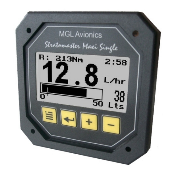
Stratomaster Maxi Single
FF-3
Dual sender fuel management system
Fuel flow, fuel range, fuel endurance, fuel level, accumulated
fuel burn, differential flow measurement. 13 modes of operation.
The FF-3 fuel management computer is a 3.5" instrument intended for efficient monitoring of fuel
related information onboard small aircraft and related applications.
The FF-3 unit can connect to one or two fuel flow senders, one or two fuel level senders or both.
Full functionality is available with both senders or only with a fuel flow sender using calculated
fuel levels based on fuel usage. Differential fuel flow calculations are also supported for fuel
return systems.
Standard automotive fuel level senders can be used, even with odd shaped tanks thanks to a
comprehensive, multi point calibration system.
Most fuel flow senders can be used and the K-factor of the sender can be entered into the system
for simple calibration. MGL Avionics supplies a lightweight dual range fuel flow sender that is
ideally suited for the FF-3 unit.
Advertisement

Subscribe to Our Youtube Channel
Related Manuals for MGL Avionics Stratomaster Maxi Single FF-3


Summary of Contents for MGL Avionics Stratomaster Maxi Single FF-3
- Page 1 Most fuel flow senders can be used and the K-factor of the sender can be entered into the system for simple calibration. MGL Avionics supplies a lightweight dual range fuel flow sender that is ideally suited for the FF-3 unit.
-
Page 2: The Main Display
The main display Fuel endurance Fuel range hours:minutes Fuel low Fuel flow alarm level Fuel level Remaining fuel Mode F+CT (Single Fuel flow, single Tank, calculated level) Mode F+PT (Single Fuel flow, single Tank, level sender) Mode DF+CT (Differential Fuel flow, single Tank, calculated level) Mode DF+PT (Differential Fuel flow, single Tank, level sender) Alternate main display for the above modes only –... - Page 3 Mode F (Single Fuel flow) Mode FF (Dual Fuel flow) Mode PT (Single Tank, level sender) Mode PTT (Dual Tank, level senders) Mode DF (Differential Fuel flow) Note: This mode is used to show the flow of both forward flow and return flow senders. The calculation at the bottom of the screen shows how the fuel flow is derived.
- Page 4 Setting up the FF-3 Press the Menu key to enter the menu. You can move forward and backwards in the menu by using the + and – keys. To change or select a menu item, move the highlight to the desired item and then press the Select (Enter) key.
- Page 5 Speed Enter your aircrafts cruising speed. This value will be used to calculate the fuel range, i.e. how far you can fly with remaining fuel at zero wind speed. For this calculation, your current remaining fuel, your current fuel flow and the speed entered here are taken into account. You can easily change the speed during flight to reflect changes in ground speed or cruising speed.
- Page 6 The K-Factor is the number of pulses generated by the fuel flow sender for one liter of fuel. The dual range fuel flow sender supplied by MGL Avionics has a K-Factor of 7000 in the low flow mode (jet installed) and 1330 for the high flow mode (no jet installed).
- Page 7 For example, assume we need 26 liters to get back to the previously marked fuel level. This means the the fuel level should have been at 24 liters as we started with a value of 40 liters. This example would mean that our fuel flow sender is under reading by four liters as it has not measured the correct quantity of fuel.
- Page 8 Calibrate 1, Calibrate 2 This function enters the fuel level sender calibration menu. The fuel level sender needs to be calibrated before it can be used with this system. The calibration allows the system to learn the shape of your tank as well as any errors your fuel level sender or installation has. Note: You only need this function if you are using your FF-3 with physical fuel level senders, there is no need for this function if you are using calculated fuel levels using the fuel flow senders.
- Page 9 If you see the number changing then everything is well. Once it has stabilized and the highlight is on the 0 Lt position, press the “Menu” key to transfer the reading from the sender to the calibration point. Now you are ready for the next step. Add the required amount of fuel to get to the next level (In our case 9 Lt –...
- Page 10 We recommend that measures are taken to prevent voltage transients in excess of this limit. MGL Avionics recommends the fitment of a fuse in line with a 33V transorb (available from MGL Avionics at low cost) to protect electronic instruments, radios and intercom systems. Only one such arrangement is required for a cluster of instruments.
- Page 11 Operation of this instrument is the sole responsibility of the pilot in command (PIC) of the aircraft. This person must be proficient and carry a valid and relevant pilots license. This person has to make him/herself familiar with the operation of this instrument and the effect of any possible failure or malfunction.
- Page 12 Connecting the senders Negative supply (airframe ground) Braid from senders Fuel flow sender 2 Blue wire from senders Fuel level sender 1 Red wire from senders Fuel flow sender 1 Terminal strip (not supplied) To other instruments Brown Blue Power Fuel level Yellow switch...
- Page 13 Please observe the installation notes supplied with the fuel flow sender. Should you install a different fuel flow sender to that supplied by MGL Avionics, ensure that you enter the K-factor relevant for your sender. Some senders require a pull-up resistor to the 12V supply line. We find most installations of these senders require a 4K7 pull-up resistor.
Need help?
Do you have a question about the Stratomaster Maxi Single FF-3 and is the answer not in the manual?
Questions and answers