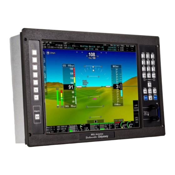
Summary of Contents for MGL Avionics EFIS G2
- Page 1 MGL Avionics EFIS G2 and iEFIS Guide to using the MGL RDAC CAN interface with the UL Power engines...
-
Page 2: Data Connections
General The RDAC CAN interface forms the bridge between the UL Power ECU and an MGL Avionics G2 EFIS system and iEFIS systems. The RDAC CAN interface provides the following: a) CAN bus Interface to ULP ECU A with fallback to ECU B on ECU A failure b) Interface to ULP ECU system via RS232 port c) 2 fuel level sender inputs with internal pullups suitable for resistive senders. -
Page 3: Throttle Position
Fuel flow rate Please configure your EFIS for a K-factor of 7000 using the “turbine” option. Manifold air pressure No EFIS configuration is needed. Please set manifold calibration to zero unless you have an accurate reference source. In that case you may use the calibration as needed. Note: This item requires an optional engine monitoring module available from UL Power. -
Page 4: Connector Pins
Functions provided by the RDAC CAN The RDAC CAN provides a number of additional sensor monitoring inputs on the D-25 connector. Fuel level sender inputs These inputs are marked “FL1” and “FL1”. These are intended for connection to resistive fuel level senders. The RDAC CAN provides internal pullup resistors (470 ohms to 3.6V). -
Page 5: Led States
10,11,14-20 No connection 21-25 Ground (same ground as power supply ground on DB 9). LED states The RDAC CAN has a LED lamp next to the DB-9 connector. This LED can be used do diagnose fault and connection issues. The LED has a two second period in which it flashes once, twice or three times depending on condition. - Page 6 Power supply requirements for the RDAC CAN Nominal 12V DC. Range: 8.5V to 36V. Voltages above 16V may only be applied short term (less than 30 seconds below 20V, less than 5 seconds to 36V). Power supply must be filtered and free of surges, spikes and noise. Current consumption: 50mA typical, maximum 70mA with fuel level senders grounded and pull up resistors switched on.
- Page 7 RDAC CAN dipswitch assignment The RDAC CAN may be assigned as RDAC 1,2,3 or 4 by means of DIP switches 1 and 2. Note: Odyssey/Voyager support only RDAC 1 and 2. Switch RDAC 1,2 RDAC 3,4 off or on DIP switch 2 is used to select RDAC 3 or 4 unless “Both ECUs” is selected Switch Send data as RDAC 1 or 3 (depending on switches 1,2) Send data as RDAC 2 or 4 (depending on switches 1,2)
-
Page 8: Status Led
If ECU B data fails, no data is sent on ECU B. Status LED The RDAC CAN has a greed status LED indicator. Single flash: RDAC CAN is powered and working but there is not data received on the ECU CAN bus. - Page 9 UL Power ECU diagnostics The UP Power ECU transmits various status messages. These can be observed in the “RDAC CAN ECU status information” in the diagnostics menu. The engine type identification number in the ECU diagnostics is "100". Device status 1 right most byte: (ULP ignition status) 00000000 all on...
- Page 10 CAN bus primer The CAN bus (Controller Area Networking) was defined in the late 1980 by Bosch, initially for use in automotive applications. It has been found to be very useful in a wide variety distributed industrial systems and is becoming popular in avionics applications due its robustness and ease of use.
- Page 11 SINGLE LOCATION ONLY. This prevents creating a “ground loop” which can cause EMI issues. Basic wiring checks You can use a volt meter to perform basic checks on a CAN connection. With at least one device connected and powered you should be able to measure voltages of around 1.0 –...


Need help?
Do you have a question about the EFIS G2 and is the answer not in the manual?
Questions and answers