Table of Contents
Advertisement
Quick Links
Introduction
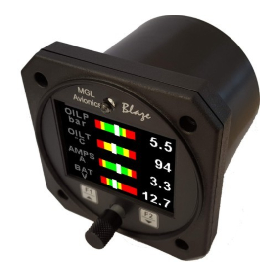
The TP-4 is a 3 1/8" (80mm) sunlight readable 4 channel universal analog input color display instrument. Each channel
can be individually programmed to display either pressure, temperature, current or volts from a universal analog input that
can interface to many sensors such as oil temperature, coolant temperature, oil pressure, fuel pressure, manifold
pressure, boost pressure and many more.
The TP-4 can display any combination of 1 to 4 analog channels in a horizontal / vertical bargraph or a numeric display
format.
Pressure can be measured using standard automotive resistive senders (e.g. VDO 2, 5 and 10 Bar), Rotax 4-20mA
senders as well as voltage output pressure senders (e.g. UMA). Temperature can be measured using standard
automotive resistive senders (e.g. VDO, Westach) as well as the MGL Avionics precision LM335 semiconductor sensor.
In addition the temperature, pressure and current inputs can be programmed to a user defined curve for custom senders.
All analog channels have a programmable low and high alarm. This results in a contact closure that is typically used to
switch a warning lamp on. The TP-4 also records the minimum and maximum values reached for each channel in
permanent memory.
The TP-4 can also be interfaced via the CAN bus to an external RDAC unit (Remote Data Acquisition Computer). This
allows for easier installation as the RDAC unit is normally mounted in the engine compartment.
Blaze TP-4
4 Channel Universal Analog input
(Pressure / Temperature / Current / Volts)
indicator
Operating Manual – English 1.04
Advertisement
Table of Contents

Subscribe to Our Youtube Channel
Related Manuals for MGL Avionics Blaze TP-4


Summary of Contents for MGL Avionics Blaze TP-4
- Page 1 (e.g. UMA). Temperature can be measured using standard automotive resistive senders (e.g. VDO, Westach) as well as the MGL Avionics precision LM335 semiconductor sensor. In addition the temperature, pressure and current inputs can be programmed to a user defined curve for custom senders.
- Page 2 Temperature can be measured using standard automotive resistive senders (e.g. VDO, Westach) as well as the MGL Avionics precision LM335 semiconductor sensor • Current can be measured using the MGL Avionics Magnetic Closed Loop Current Sensor (Sold Separately) • High accuracy: Built in linearization curves for common senders •...
-
Page 3: Main Displays
Blaze TP-4 Operating Manual Page 3 2 Layout Ambient light sensor 3 1/8” (80mm) enclosure. Can be front or rear mounted Sunlight readable color graphic display: The backlight can automatically adjust to the ambient light or it can be manually... -
Page 4: Horizontal Display
Blaze TP-4 Operating Manual Page 4 3.1 Horizontal display The below images show the horizontal display mode displaying 1,2,3 and 4 channels 3.2 Vertical display The below images show the vertical display mode displaying 1,2,3 and 4 channels 3.3 Numeric display The below images show the numeric display mode displaying 2,3 and 4 channels 3.4 Maximum Values display... -
Page 5: Exiting The Menu System
Blaze TP-4 Operating Manual Page 5 4 Menu System Press the rotary control button during the normal display mode to enter the menu system. Use the rotary control to navigate through the menu system. 4.1 Exiting the menu system Press the F1/Up button to exit the menu system when the “EXIT” soft key is shown. All changes made during navigation of the menu system will be saved in non-volatile memory upon exiting. -
Page 6: Pressure Setup
Blaze TP-4 Operating Manual Page 6 4.2 CH1 to CH4 Setup (Analog Channel Setup) The 4 analog channels are universal analog input channels that can be used for pressure, temperature, current or volts. Only “CHANNEL 1” Setup is shown below, follow the same steps for Channel 2, 3 & 4 4.2.1 Pressure Setup... - Page 7 Blaze TP-4 Operating Manual Page 7 Model: Select which VDO pressure sender you are using. A selection between a VDO 2, 5 or 10 Bar can be selected. If the “VOLTAGE” pressure sender is selected Sender: Select the type of voltage sender you are using. Select “UMA” for UMA senders, "0.5-4.5V" for voltage senders, or “USER”...
- Page 8 Blaze TP-4 Operating Manual Page 8 High Caution: Enter the pressure value for the high caution. This is the lower value of the upper yellow band. Low Caution: Enter the pressure value for the low caution. This is the upper value of the lower yellow band.
-
Page 9: Temperature Setup
Blaze TP-4 Operating Manual Page 9 4.2.2 Temperature Setup Mode: Select the function for the analog channel. Options are “PRESSURE”, “TEMP”, “CURRENT”, “VOLTS” or “OFF”. Sender: Select what type of sender you are using. Select “VDO 120” for a VDO 120 degree NTC sender, Select “VDO 150” for a VDO 150 degree NTC sender, “WESTACH”... - Page 10 Blaze TP-4 Operating Manual Page 10 Select the maximum temperature that you want the bargraph to show. This can give you increased display resolution. Display Min: Select the minimum temperature that you want the bargraph to show. This can give you increased display resolution.
- Page 11 Blaze TP-4 Operating Manual Page 11 4.2.4 Current Setup (MGL Avionics agnetic Closed Loop Current Sensor required) Mode: Select the function for the analog channel. Options are “PRESSURE”, “TEMP”, “CURRENT”, “VOLTS” or “OFF”. Label: Enter a label to suit your current channel so you can identify it easily.
-
Page 12: Zero Sensor
Adjust the gain factor until the current is reading correctly. It will be best if a multimeter can be inserted in series with the current supplying conductor and the gain calibration adjusted until the TP-4 matches that of the multimeter. Please see the MGL Avionics Closed Loop Current Sensor documentation for more information. Data: Select the data source of the current signal. - Page 13 Blaze TP-4 Operating Manual Page 13 4.2.5 Volts Setup Mode: Select the function for the analog channel. Options are “PRESSURE”, “TEMP”, “CURRENT”, “VOLTS” or “OFF”. Label: Enter a label to suit your volts channel so you can identify it easily.
-
Page 14: Protocol Format
Blaze TP-4 Operating Manual Page 14 4.3 COMM Setup (Communication Setup) Serial Out: Select “ON” to enable the RS232 serial output. Unit Address: Enter the unit address. Baud Rate: Select the desired baud rate of the serial output. The transmission format is set to 8 data bits, No parity, 1 stop bit. The baud rate can be changed in the Communication Menu. - Page 15 Blaze TP-4 Operating Manual Page 15 4.3.2 Data payload Message type=8 Data Length=10 bytes Output Rate=1Hz Analog Channel Type: Unsigned Int (16 bits) CH4 (4 bits), CH3 (4 bits), CH2 (4 bits), CH1 (4 bits) 0=Off 1=Pressure 2=Temperature 3=Current 5=Volts...
-
Page 16: Security Setup
Blaze TP-4 Operating Manual Page 16 4.4 MISC Setup (Miscellaneous Setup) Backlight: Select manual or automatic backlight control. Use the rotary control in manual mode to adjust the backlight brightness. Allow 3 seconds for the display to adjust to the ambient lighting conditions when using the automatic backlight mode. -
Page 17: Loading Factory Default Settings
Blaze TP-4 Operating Manual Page 17 Information: This menu option displays information about the unit. Default Settings: Select this menu option to reset all the settings to factory defaults. 5 Loading factory default settings Press and hold the F1/Up button and rotary control during power up to load the pre- programmed factory default settings. -
Page 18: Error Messages
Blaze TP-4 Operating Manual Page 18 6 Error Messages Unit settings CRC error. Load default settings to restore to factory defaults. If the error message still persists then it could possibly be a non-volatile memory failure in which case the instrument will then have to be returned to the factory. -
Page 19: Specifications
Blaze TP-4 Operating Manual Page 19 7 Specifications Operating Temperature Range -10ºC to 60ºC (14ºF to 140ºF) Storage Temperature Range -20ºC to 80ºC (-4ºF to 176ºF) Humidity <85% non-condensing 8 to 30Vdc SMPS (switch mode power supply) with built in 33V over... -
Page 20: Firmware Upgrading
User defined senders: The TP-4 has a user sender calibration feature that can be customized for senders not listed above Current Sensors MGL Avionics Magnetic Closed Loop Current Sensor Voltage measurement range Up to 32Vdc Voltage resolution 0.1V 8 Operating the alarms The alarm output can be used to switch an external alarm indicator. -
Page 21: Installation
Blaze TP-4 Operating Manual Page 21 10 Installation 10.1 Temperature senders VDO Resistive senders: The TP-4 supports the VDO 120ºC and 150ºC thermistor automotive senders. The internal pull up resistor dip switch for the resistive temperature sender input must be in the “ON” position. - Page 22 Blaze TP-4 Operating Manual Page 22 10.3 Senders that are grounded in the engine block Single wire senders require that their mounting arrangement (thread) has a very good electrical contact with the engine block. Avoid the use of any sealant or tapes as these may cause a bad electrical connection. Further to this it is very important that the engine block has a good electrical connection to the negative supply terminal of the TP-4.
- Page 23 Page 23 10.6 Closed Loop Current Sensor The MGL Avionics magnetic closed loop current sensor provides a 0.5V to 4.5Vdc output voltage which is proportional to a 50A bi-directional input current. Advantages of closed loop current sensors over conventional current measurements techniques is that they provide the highest accuracy, are ideal for noisy electrical environments and they provide complete electrical isolation f rom the current carrying conductor.
-
Page 24: Cable Connections
Blaze TP-4 Operating Manual Page 24 10.8 Cable connections Main connector (D15HD connector: Unit Female, Cable Male) D15HD Pin Wire Color Function 8-30Vdc power via power switch / circuit breaker and fuse. Black Ground. Connect the ground to the engine block, and the engine block to the battery negative. -
Page 25: Connection Diagram
Blaze TP-4 Operating Manual Page 25 10.10 Connection Diagram The use of an external 1A fuse is recommended. Connect the supply terminals to your aircrafts power supply. The TP-4 can be used on both 12V and 24V without the use of any pre-regulators. Ensure that the supply voltage will not drop... - Page 26 Blaze TP-4 Operating Manual Page 26 11 Dimensions...
-
Page 27: Warranty
IMPORTANT NOTICE: You must make your own determination if the products sold by MGL Avionics are safe and effective for your intended applications. MGL Avionics makes no representations or warranties as to either the suitability of any of the products we sell as to your particular application or the compatibility of any of the products we sell with other products you may buy from us or anywhere else, and we disclaim any warranties or representations that may otherwise arise by law. - Page 28 Blaze TP-4 Operating Manual Page 28 Other instruments in the Stratomaster Blaze series AHRS-2 Artificial Horizon and Magnetic Compass Indicator AHRS-4 Self contained Artificial Horizon and Magnetic Compass Indicator ALT-6 Altimeter and Vertical Speed Indicator (VSI) ALT-7 Altimeter and Vertical Speed Indicator (VSI) with a transponder compatible RS232 &...
Need help?
Do you have a question about the Blaze TP-4 and is the answer not in the manual?
Questions and answers