Advertisement
Quick Links
IEFIS G4 user manual
This document details the user interface for an iEFIS panel. The generation 4 (G4) refers to
the processor core hardware. Much of this document is also applicable to G1, G2 and G3
systems as the firmware is based on these generations.
Document date: 28 October 2024
Additional references (more on the MGL Avionics website):
iEFIS GPS manual
iEFIS alteration guide
iEFIS G4 installation manual
iEFIS G4 diagnositics manual
iEFIS User Screen designer
iEFIS Ground proximity and flap overspeed setup
iEFIS Navigation manual
iEFIS Autopilot manual
iEFIS Plates, iEFIS PocketFMS plates
iEFIS Mode-s/ADS-B
iEFIS I/O – Using inputs,outputs and alarms
Page 1
Advertisement

Subscribe to Our Youtube Channel
Related Manuals for MGL Avionics IEFIS G4


Summary of Contents for MGL Avionics IEFIS G4
- Page 1 Much of this document is also applicable to G1, G2 and G3 systems as the firmware is based on these generations. Document date: 28 October 2024 Additional references (more on the MGL Avionics website): iEFIS GPS manual iEFIS alteration guide...
-
Page 2: Table Of Contents
Table of Contents General............................5 IEFIS capabilities........................6 Full systems including iBOX....................6 “Lite” systems........................7 IEFIS documentation......................... 8 The G4 system.......................... 9 The G4 CPU card........................10 The Linux operating system....................10 Main differences G4 to G3 and earlier.................11 The iEFIS panel in detail......................12 Touch screen........................ - Page 3 Canceling an active flight plan..................... 37 The Flightplan popup......................38 The menu system........................42 Supplementary Waypoint editor..................42 Primary Navidata waypoint viewer..................43 Secondary Navidata waypoint viewer................. 43 Flightplan tool........................43 Information system menu....................43 Common Tasks........................43 Install Tasks.........................44 System setup menu......................44 3D View setup........................44 File manager........................
- Page 4 Install NaviData database(s)....................62 Install supplementary waypoint file..................63 Install weight and balance files.................... 63 Install or remove raster maps....................63 Delete current screen files in screens folder...............63 Install screen files to screen folder..................64 Install World image (Map)....................64 Install sound file from SD/MMC card................... 64 Common tasks menu.......................
-
Page 5: General
General The iEFIS panels are available in two versions – a “full” version which includes one or two iBOX units that contain all interfacing or a “lite” version which has built in sensors and some interfaces. The two versions are not compatible with each other and are not used mixed in the same aircraft. -
Page 6: Iefis Capabilities
Traffic systems compatible with ARINC 735 (TIS, TCAS, ADSB with TIS output) Traffic systems: ADS-B receivers with GDL90 protocol, FLARM, XRX PCAS Transponders requiring greycode (gillman code) altitude encoder can be connected, using the iBOX altimeter as alticoder source. These transponders are not supported by “Lite” systems. Older navigation systems (VOR/ILS) using +/-150mV differential outputs to drive indicators can be connected as navigation source (iBox systems only).. -
Page 7: Lite" Systems
EFIS controlled COM radios, NAV radios and transponders, both mode-c and mode-s may be fitted for a complete, cost effective solution. Each iEFIS panel may be connected to video sources such as taxi or night vision cameras as standard. The modular concept of iEFIS allows not just a tailormade solution, if desired each panel can be customised by the owner using a freely available “screen design”... -
Page 8: Iefis Documentation
MGL Autopilot manual. iEFIS G4 Installation manual iEFIS G4 Alteration guide (needed if custom screen designs are to be attempted) In addition please refer to the manuals related to individual devices and interfaces. Manuals are available on the MGL Avionics home website: www.MGLAvionics.co.za... -
Page 9: The G4 System
The G4 system The “G4” refers to the MGL Avionics G4 CPU board that replaces the previous G3 system. It can also be used to upgrade older G1 and G2 systems. The G4 uses Linux as operating system (previous versions used the MGL “FlightOps”... -
Page 10: The G4 Cpu Card
The G4 CPU card The G4 is based on the ST Microsystems STM32MP157 processor. It provides two ARM Cortex A7 cores, one Cortex M4 core and a Vivante graphics processor (GPU) as well as a rich collection of peripherals on a single chip. The remainder of the CPU card provides a 2MByte battery backed memory chip, a 512MByte DDR3 memory chip, SD card holder, 16Mbyte flash memory and power supply circuits. -
Page 11: Main Differences G4 To G3 And Earlier
For details on how the use the built-in screen design facility please refer to the document “iEFIS G4 user screen designer”. For more details on screen designs in general please view the document “iEFIS Alteration guide”. -
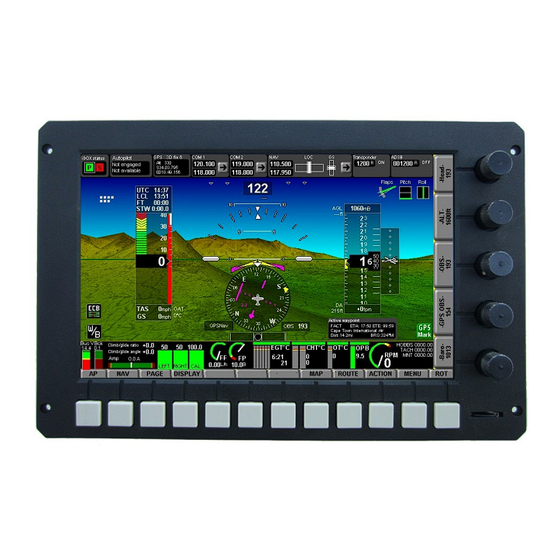
Page 12: The Iefis Panel In Detail
The iEFIS panel in detail This image shows the Explorer panel. The Challenger panel has identical controls but a slightly different screen layout. The MX2 does not have the button array but mimics the buttons using the touch screen and has four instead of five rotary controls. -
Page 13: Rotary Controls
Rotary controls The 5 rotary controls have strong indents during rotation to allow positive selection of a desired value. Many rotary functions have a dual level. The second level can be obtained by pressing the rotary control towards the panel while turning. For example, this is used when selecting a COM frequency: First select the MHZ, then press and turn to select the KHZ. - Page 14 The above image shows a typical small dual panel system with a single iBOX. The above image shows a typical “Lite” system. The “Lite” system does not have an ibox. Instead the panels themselves are fitted with pressure senders for altimeter and airspeed with some models also providing an AOA sensor.
-
Page 15: Iefis Default Screens
IEFIS default screens Default screens refer to screen layouts that are “built-in” to a panel. Various types of default screens and parts of default screens can be chosen in the system setup. Layouts refer to the general organization of a screen while details refer to parts of a screen. A detail may relate to the monitoring for a particular engine type or a fuel system setup. - Page 16 Reveal hidden icons Some of the interaction with the touch screen is via hidden icons. Some icons that are not used often are hidden. Tapping the hidden icons field will reveal these icons and they will then remain visible for a number of seconds.
-
Page 17: Adjusting Local Pressure (Qnh Or Baro Pressure)
This field shows UTC time from GPS, your local time (kept in the iBOX), flight time if a flight is active and also a stop watch. Tap in this field to bring Tap here when done This pop up allows you to start, stop and reset the stopwatch. Further to this you have a count down timer. - Page 18 Tap in this area to increase local pressure by two digits Tap in this area to increase local pressure by one digit Tap in this area to decrease local pressure by one digit Tap in this area to decrease local pressure by one digit The altimeter is setup to show a tape, digital readout, local pressure (shown here in millibar), elevation above ground level (AGL) , density altitude (DA) and vertical speed (VSI).
- Page 19 Two heading displays are available, the top, larger heading display is derived from GPS ground track, corrected for local magnetic variation. GPS track (magnetic) The smaller readout below if derived from the magnetic compass sensor (if available in your installation). In still air (no wind) and with the aircraft not slipping, the two numbers should be very similar.
-
Page 20: Additional Touch Functions
Simulator and Screen Designer application. The image file is typically created using a standard image editor on a PC and converted to MIF format using the MGL Avionics MIF converter application. You can also use standard JPEG image files so no conversion is needed. - Page 21 Typical Weight and Balance calculator image. Stations and their functions are selected in the Weight and Balance editor accessible from the weight and balance function display screen. Stations refer to points that are a certain distance from a datum point on the aircraft. Consult your aircraft manual for the location of the datum point.
-
Page 22: Radio And Status Panel
Radio and Status panel Some screen layouts may provide a partial or full Radio panel. The example screen layout provides a full panel on top of the screen. All panel items are touch sensitive and provide localized functionality or open larger “pop up” devices as described here. -
Page 23: Ibox Status Pop Up
forced changeover due to a system fault or maintenance or setup is performed on the standby iBOX (in this case it must become the active iBOX so it becomes possible to perform certain operations. IBOX status pop up Tapping the iBOX status will open the iBOX status dialog. This dialog gives more detailed information and allows you to select master or standby iBOX for setup or maintenance work to be performed. -
Page 24: Raim Information
- 3D fix This is followed by the number of satellites tracked RAIM information If RAIM is enabled, the ALT field will alternate between: ALT GPS altitude if 3D fix Rm RAIM status RAIM status gives you the current RAIM error limit estimate as follows: Rm OFF - The RAIM system is not operating. -
Page 25: Gps Status Dialog
Please consult the separate manual “iEFIS GPS.pdf” available from the MGL Avionics website. Also consult the manual “ModeS-ADSB.pdf” from the MGL Avionics website which has details on the various GPS sources and how to use them in the ADS-B context. -
Page 26: Com Radio Dialog
COM radio dialog Flip Main Enter frequency into standby Standby Names, functions if exist Select a frequency From a list Radio setup (MGL radios only) Tapping the frequencies will flip main and standby frequency. Entering frequencies using the numeric keypad requires entering of 6 digits, for example, 123450 will set frequency 123.450 MHZ. - Page 27 120.01 test 1 121.02 test 2 121.03 test 3 121.04 test 4 121.05 test 5 121.06 test 6 121.07 test 7 121.08 test 8 121.09 test 9 ;---end of file (this text is not required to be in the file ---- Copy this text file into your panels “Other”...
-
Page 28: Nav Radio
NAV radio The NAV radio is based on the capabilities of the connected navigation system. For example, if you have a Garmin SL30 NAV/COM connected your will be able to use dual VOR navigation or ILS/Glideslope. Even if you have no NAV radio connected, the NAV radio is still functional. Using the navigation database and the GPS it can emulate a real VOR navigation system. -
Page 29: Transponder
Note: If a NAV radio is connected and navigation is flagged valid, emulated GPS based VOR navigation is automatically suppressed. Transponder If you have a remote controlled transponder connected to the system, you can tap on the transponder display to open the transponder dialog: Tap to activate Ident Enter the sqwauk code... -
Page 30: Transponder Setups
Setup for mode-c transponder Setup for mode-s transponder Transponder setups Please select the relevant entries depending on the transponder type. Select the type of squat switch you would like to use. Squat switch tells your transponder if you are on the ground or airborne. Selections: Use EFIS flight detect, Use external input on iBOX or iEFIS Extender, or “in flight”... -
Page 31: Adsb
ADSB The iEFIS system supports ADS-B receivers as well as ADS-B transceivers (978Mhz UAT). Any ADS-B receiver supporting the GDL-90 communications standard for ADS-B can be used. The ADS-B status display and dialog is only relevant for ADS-B transceivers (“ADS-B out”). Tap on the ADS-B status display to open the ADS-B dialog. - Page 32 Please note the “Slave ADSB” in the ADSB setup menu. This allows you to synchronize the ADSB transceiver with your transponder if you have a remote control transponder connected to your iEFIS system. If synchronization is activated, transponder and ADSB will transmit the same sqwauk codes. Ident is also synchronized.
-
Page 33: Waypoint Information
Waypoint information If a GPS waypoint is active, the waypoint information box is visible: Information available in this display is: Short and long waypoint names, Estimated time of arrival assuming a great circle line flight to the destination at current ground speed, estimated time en-route. Distance to go and magnetic bearing to destination complete the information. -
Page 34: Gps Mark Position
GPS mark position You can mark the current position at any time. Tap the GPS mark position and you will be presented with a waypoint editor: Here you may edit the newly created waypoint. You may want to give it a name. Finally select where you would like to save the waypoint to. -
Page 35: Flight Plans
Flight plans Flight Plans are managed via the FPLAN button. If no flight plan is current active you will be taken to the Flight Plan manager. If a Flightplan is active you will see the active Flightplan popup. If the Flightplan popup is showing tapping the FPLAN button will hide the Flighplan (it remains active). -
Page 36: Activate Flightplan, Activate Flightplan In Reverse
Flight plans are files with a name that usually describes the flight plan. Note that you should not use names longer than 30 characters (plus the file extention) with the G4 – it will truncate longer names for brevity. Once you have activated an external flight plan you can reuse it from internal disk storage. Activate Flightplan, Activate Flightplan in reverse These two functions are very similar. -
Page 37: View Or Edit A Flightplan
View or Edit a Flightplan You will be be presented with a menu allowing you to choose a flightplan from your internal disk storage (The Flightplan folder you can also access via the built in file manager). Once you selected your flight plan it will be loaded and you will be taken to the flight plan tool where you can view and edit the flight plan. -
Page 38: The Flightplan Popup
The Flightplan popup The Flightplan popup shows if you tap the FPLAN button while a flight plan is active. To hide the Flightplan simply tap the FPLAN again. If you tap the FPLAN twice rapidly (within a second) and the flight plan popup is not showing you will be taken to the Flightplan manager. The Flightplan popup shows the next and previous waypoints of the active flight plan in bottom to top order (i.e. - Page 39 each waypoint based on your current ground speed from your GPS. If you tap on any of the waypoints in the list you will select that waypoint for further action (if any). The waypoint selected will have a PURPLE background. At the same time the context of the touch fields at the bottom of the display changes: This will remain for a short while before reverting back to the normal display.
- Page 40 INFO will show available information for the selected waypoint such as frequencies or other information as defined in your navigation database. Example: FUEL changes the popup into Fuel consumption mode: Assuming you have a fuel flow sender installed and configured the MX1 will calculate the fuel needs for every leg in your flight plan and also give you required fuel totals.
- Page 41 MANAGE will lead you to the flight plan manager. Waypoints behind are not forgotten Here you can see an example of waypoints that are behind you. The current waypoint here is FAFK and we still have a few minutes to go. At the same time we can see the last waypoints we passed and also see distances and course information should we need to return.
-
Page 42: The Menu System
The menu system Press the “Menu” softkey button to activate the menu system. The menu itself occupies most of the screen to allow sure use of the touch screen to select items. A smaller part of the screen is dedicated to a screen design showing essential flight instruments. -
Page 43: Primary Navidata Waypoint Viewer
waypoints that the system can use in addition to those provided in the navidata file(s). Please consult the “iEFIS Navigation manual” for detailed information on this function. Primary Navidata waypoint viewer The primary navidata file contains navigation data provided either by a third party such as Jeppesen or you can also create and maintain your own navidata file using the MGL Central application. -
Page 44: Install Tasks
Install Tasks This is a collection of automated installation functions you can choose to copy data files to the system such as map and terrain files. System setup menu This is the entry point to a comprehensive system setup menu. This is described in detail in the iEFIS installation documentation. -
Page 45: The Flightplan Tool
The Flightplan Tool The Flight plan tool starts with the option of creating a new route or editing an exiting route using the FPLAN button from any page display. Move (PAN) the map by tapping on the location you want the map to be centered at the cross hairs. -
Page 46: Add Waypoint
Flight plans are stored in your internal drive in the folder “Fplan”. Flight plans files can be copied using the file manager. You can also use the “Flightplan manager” and seldom will need to access these files directly. Once a route is open the right hand pane shows the route details. You can navigate the Flight plan using the touch screen. -
Page 47: Add Map Position
"KLAX 503010N08923W" as entry would define two waypoints. KLAX (Los Angeles International) to a point at N50:30:10 W89:23:00. You can enter multiple points on one line, up to 250 characters at a time. If you use an identifier (such as KLAX) and this cannot be found in any database (including your supplementary database) the import stops at that item with a message. -
Page 48: Map Options
Map options Here you select which navigation database waypoints to display as well as airspace types. Note that every zoom level has its own settings. Select the zoom level you would like to change before tapping the Map Options button. Page 48... -
Page 49: Working With Maps
Working with maps Typical map view – here we have a “track up” display Track Range ring Range ring Time to reach Distance At current speed Track line: RED: not enough fuel GREEN: enough fuel to Get to waypoint At current performance Your position Your... -
Page 50: Mode
Tap on the map and you get: Mode Allows you to select the map in either track up or north up modes. You can also select from several different installed map styles if you have more than one style installed. Note: Every page that has a map maintains its own settings and these are remembered if the system is switched off. -
Page 51: Divert
Divert This function allows you to define a multipoint divert and even create a flight plan from your entries. You need to have an active waypoint. This has a track leading to it. You can add up to 20 points anywhere on the map and reshape the track to follow your divert. You can also save your divert as a new Flightplan. -
Page 52: Retrack
This is what it looks like after we activated our Divert. In effect it has created a flight plan with three waypoints – we created two along the Divert and the third one is our original waypoint. With the Divert now active, tapping on the map gets us: Note that a DivEnd button has been added. -
Page 53: Map Information Mode
Map information mode Tapping on the map twice from normal soft key mode gets you: Page 53... -
Page 54: Airport
In this mode tapping any location on the map does two things: A yellow line shows the track between the current aircraft position and the point you touched on the map. A grey popup at the touch location shows the distance to that point and how long it would take you to get there at current ground speed. -
Page 55: Panning The Map
time out – it will return to normal mode after a few seconds). Panning the map Sometimes it is required to view the map in locations that are not visible on the screen. Most touch screen devices like your mobile phone allow dragging of maps with your finger. In a cockpit environment with typical mounting positions of an EFIS system this does not work well. -
Page 56: P-Off
P-off Switch off PAN mode and revert to normal map mode with the map location centered at current position. P-hold This suspends PAN node at the current PAN location allowing you to touch the map without moving it. In PAN hold mode all the normal map touch functions work such as obtaining information on airspaces, distances and time to a map point as well as activating a GOTO. -
Page 57: Map Display In Panning Mode
Map Display in Panning mode Page 57... - Page 58 Page 58...
-
Page 59: The Rotary Controls
The rotary controls Rotary controls work in pages. Simply flip through the available pages using the “ROT” softkey below the rotary control column. Airspace display selections Base map items selected for display Waypoint types selected for display Certain of the rotary control pages are automatically selected if you open specific devices. For example, if you open a COM radio, the corresponding radio controls are selected. -
Page 60: Waypoint Selection System
Waypoint selection system The EFIS contains a common structure to view or select waypoints. Depending on the context, the function operates in slightly differing ways. Here we start with the most common – using the “Direct goto” function to select a waypoint. There are several ways to activate this function: This icon is available after tapping the reveal icon on the standard EFIS screens. - Page 61 database you can search for this. Note the “Types” button. Tap this to bring up a popup where you can select which types of waypoints to include in the list. Waypoint types are “Airports”, “Navaids”, “intersections”, etc. You may select a waypoint that is included on any flight plans you have stored on your system.
-
Page 62: The Installation Tasks Menu
There are also free databases available, for example the data used for North America is supplied by the MGL Avionics user forum based on the regular FAA data release. You can also create your own data using the MGL Central application. -
Page 63: Install Supplementary Waypoint File
This installs the files WB.MIF and WB.DAT. The WB.MIF file is an image file created by the MGL BMP to MIF converter (available for download from the MGL Avionics website). The WB.DAT file defines your weight and balance stations and related information. This file is created in your MX1 Screen designer and simulator application. -
Page 64: Install Screen Files To Screen Folder
The sound file is named SOUNDS.ESD and is created by the Enigma Voice application available for download on the MGL Avionics website. It converts standard 8-bit, 8Khz sample rate, monaural sounds in WAV format. MGL Avionics offers two of these files for download on their website: A male and a female voice version. -
Page 65: Common Tasks Menu
This function allows you to extract this data onto an external SD card. It can be viewed in the IEFIS flight data recording viewer. This application is a free download from the MGL Avionics Page 65... -
Page 66: 3D View Setup
website. 3D View setup This menu contains items that affect your horizon display. Page 66... -
Page 67: Attitude Graticule Display
Attitude graticule display This allows you to switch the pitch and roll displays on or off. View uses pressure altitude Here you can select if your forward view should use pressure altitude (with local barometric correction) or altitude from your GPS. The recommendation is to use pressure altitude unless you are flying in an area that has wide area GPS augmentation coverage that can significantly reduce vertical errors of the GPS position. -
Page 68: Show 3D Highway In The Sky
would not select this if you are flying a three axis aircraft. Show 3D highway in the sky Select if you would like to make use of the 3D highway in the sky. This shows you green boxes you “fly” through to stay on track and on altitude. Here you see a highway in the sky and we are getting close to the waypoint. -
Page 69: Pitch Ladder Banks
Pitch ladder banks Select if you would like your pitch ladder to bank or to remain vertical regardless of roll attitude. Enable 2D traffic on SV This function, if enabled will show you nearby traffic as symbols centered around the center of your horizon display. - Page 70 detected is very slightly above your finger rather than underneath. This is a personal preference but you can calibrate the screen any way you like. You will find the touch screen calibration function towards the end of the System Setup menu. You can also activate the touch screen calibration function by holding down the top right rotary control (press towards the panel, past the “click”...
-
Page 71: The System Setup Menu
The System setup menu is perhaps the most important menu in your system. Here you will find all of the setups to customize your system to you aircraft and mission. The system setup menu is described in detail in the iEFIS G4 installation manual. The Diagnostics menu The last item in the main menu is the System Diagnostic menu.
Need help?
Do you have a question about the IEFIS G4 and is the answer not in the manual?
Questions and answers