Table of Contents
Advertisement
Quick Links
Introduction
The AV-2 is a 3 1/8" instrument that can be used as a display interface for an artificial horizon reference system (AHRS),
an advanced digital compass, or both depending on which MGL Avionics sensor packages is connected to the AV-2.
The AV-2 can be setup to display the following:
•
Compass with five different displays (requires MGL Avionics SP-2 sensor package)
•
Horizon with or without slip indicator (requires MGL Avionics SP-3/4/5 sensor package)
•
Turn and bank indicator (requires MGL Avionics SP-3/4/5 sensor package)
•
Combined compass and horizon display with bank indicator and optional slip indicator (requires MGL Avionics
SP2 & SP-3/4/5 sensor package)
You can also share sensor packages between various different sizes of instrument e.g. Infinity 2 1/4" AV-1 units. For
example you may want a 3 1/8" horizon display but a 2 1/4" compass/turn and bank indicator.
1 Features
•
Artificial horizon reference system (AHRS) display unit with slip indication as well as turn and bank
indication
•
Advanced magnetic compass with course steering feature
•
Can be setup as an individual compass display, artificial horizon or both
•
The AV-2 is connected to the sensor packages by a simple 2 wire communication link. This allows for the
optimum placement of the sensor package in the aircraft
•
More then one AV-2 can be connected onto an airtalk link. This allows the compass, artificial horizon and
the turn and bank indicator to be displayed on different AV-1/2 units
•
Standard 3 1/8" aircraft enclosure (can be front or rear mounted)
•
Rotary control plus 2 independent buttons for easy menu navigation and user input
•
A red LED illuminates when the artificial horizon sensor range has been exceeded
•
Large backlit graphic LCD with adjustable contrast
•
Wide input supply voltage range of 8 to 30V DC with built in voltage reversal and over voltage protection
for harsh electrical environments
•
Light weight design
•
Field upgradeable firmware
•
1 year limited warranty
AV-2
Artificial horizon and advanced
magnetic compass indicator
Operating Manual – English 1.00
Advertisement
Table of Contents

Related Manuals for MGL Avionics AV-2


Summary of Contents for MGL Avionics AV-2
- Page 1 Introduction The AV-2 is a 3 1/8” instrument that can be used as a display interface for an artificial horizon reference system (AHRS), an advanced digital compass, or both depending on which MGL Avionics sensor packages is connected to the AV-2.
-
Page 2: Main Display
This allows you to use any combination of horizon, turn and bank or compass displays. You can connect further AV-2 or AV-2 units should you require this for a dual cockpit layout. Up to six AV units can be configured to give you 2 x... -
Page 3: Turn And Bank Indicator
AV-2 Operating Manual Page 3 3.1 Artificial Horizon with Compass 10 degree pitch bars Magnetic (M) or true heading (T) indicator Mini turn and bank indicator (can be switched on or off in the menu system) Magnetic true heading reading... -
Page 4: Digital Compass
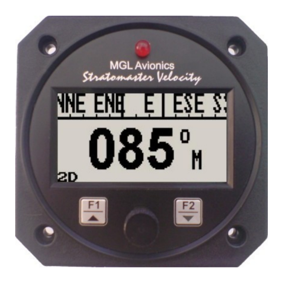
AV-2 Operating Manual Page 4 Extended range of operation Bank operates over a full 360 degree range allowing unlimited use of the horizon for aerobatics, provided that maximum published bank, pitch and yaw rates are not exceeded. Maximum rates under normal operation are approximately 165 degrees per second, valid for all three axis simultaneously. - Page 5 AV-2 Operating Manual Page 5 3.3.3 Cardinal 1 compass display The heading tape shows headings as major and minor cardinal points: N, NNE, ENE, E, ESE, SSE, S, SSW, WSW, W, WNW, and NNW Magnetic (M) or true (T) North indicator Please see the table under section 4.4 for...
- Page 6 Each measurement interval of 0.5 seconds consists of a computational evaluation of 12.000 individual measurements of the magnetic field at the magnetometer sensors. 3.4 Sensor communication error Should the AV-2 lose communication with the SP-X instrument for the duration of 5 seconds or more, the AV-2 will display the following message:...
-
Page 7: Menu System
Page 7 4 Menu System Pressing the rotary control button during the normal display mode will cause the AV-2 to enter the menu system. Use the up/down keys or the rotary control to navigate through the menu system. 4.1 Exit Menu Pressing the rotary control on this menu item will cause the AV-2 to exit the menu system. -
Page 8: Compass Setup
AV-2 Operating Manual Page 8 Move the highlight over the “DONE” menu item and press the rotary control to return to the main menu Select if you would like to enable the slip indicator to be shown underneath the horizon display. - Page 9 AV-2 Operating Manual Page 9 Select whether you want the mini compass to be shown on the horizon display screen Select the desired compass display mode as described in section 3.4 above Select whether you would like the instrument to display magnetic or true heading. If you select true heading, you need to enter the correct magnetic variation for your location.
- Page 10 AV-2 Operating Manual Page 10 Using the deviation calibration feature When you install your compass sensor package, it may be surrounded by several items or materials that in some way change the strength and/or direction of the earth magnetic field that your sensors are measuring. If left unattended, this may contribute to considerable errors in the heading as indicated by your instrument.
- Page 11 AV-2 Operating Manual Page 11 the compass. This may be a legally required procedure in your country for your aircraft class. Please check your relevant regulations. Deviation compensation and compass swing may need to be repeated from time to time as the magnetic properties of metals in your aircraft may change over time.
-
Page 12: Loading Factory Default Settings
• If you have a digital compass from the MGL Avionics range, set it to 2D or 3D-A mode and use the course steering function to help you maintain a straight path. This way you have a backup should the horizon become invalid for whatever reason. -
Page 13: Installation
12V and 24V without the use of any pre-regulators. Ensure that the supply voltage will not drop below 8V during operation as this may result in incorrect displays. Should you be installing more than one AV-2 unit, use standard RCA splitter cables to create more nodes on the airtalk-cable. - Page 14 AV-2 Operating Manual Page 14 10.2 AV-2 DB9 Cable connections DB 9 Pin Color Function Black Ground RCA (Inner cable) Airtalk communication link 8-30Vdc power...
-
Page 15: Warranty
AV-2 Operating Manual Page 15 11 Warranty This product carries a warranty for a period of one year from date of purchase against faulty workmanship or defective materials, provided there is no evidence that the unit has been mishandled or misused. Warranty is limited to the replacement of faulty components and includes the cost of labour.
Need help?
Do you have a question about the AV-2 and is the answer not in the manual?
Questions and answers