Table of Contents
Advertisement
Quick Links
Introduction
The FF-1 fuel management computer is a 2.25" instrument intended for efficient monitoring of fuel related information for
single or dual fuel tanks onboard small aircraft and related applications.
The FF-1 unit can connect to one or two fuel flow senders, one or two fuel level senders or both. Full functionality is
available with both senders or only with a fuel flow sender using calculated fuel levels based on fuel usage. Differential
fuel flow calculations are also supported for fuel return systems. Fuel injector systems are also supported. Standard
automotive fuel level senders can be used, even with odd shaped tanks due to a comprehensive, multi-point calibration
system. Most fuel flow senders can be used and the K-factor of the sender can be entered into the system for simple
calibration. MGL Avionics supplies a lightweight dual range fuel flow sender that is ideally suited for the FF-1.
In addition, the FF-1 can use the airspeed (via the airtalk cable connected to a Infinity ASI-1/ASX-1 indicator) or actual
ground speed (by using the optional FF-1 to RS232 GPS cable connected to a RS232 NMEA enabled GPS receiver) to
determine fuel range.
1 Features
•
Advanced fuel computer with 17 different modes of operation
•
Supports single or dual fuel tanks
•
The FF-1 can connect to one or two fuel flow senders, fuel level senders or fuel injectors
•
Differential fuel flow calculations are also supported for fuel return systems
•
The FF-1 has the ability to connect to an ASI-1/ASX-1 or a NMEA enabled GPS receiver for range based
calculations. It can also accept a manually entered estimate cruising speed if an ASX-1/GPS is not
available.
•
Standard automotive fuel level senders can be used, even with odd shaped tanks due to a comprehensive,
multi-point calibration system
•
Bilingual support (English and French)
•
Standard 2.25" aircraft enclosure (can be front or rear mounted)
•
Rotary control plus 2 independent buttons for easy menu navigation and user input
•
Alarm output as well as a red LED illuminates when the fuel level is below the fuel level alarm value
•
Large backlit graphic LCD with adjustable contrast
•
On board voltage reversal and over voltage protection for harsh electrical environments
•
SMPS (switch mode power supply) for use in both 12V and 24V systems as well as for reduced power
consumption
•
1 year limited warranty
FF-1
Fuel management computer for
single or dual fuel tanks
Operating Manual – English 1.10
Advertisement
Table of Contents

Related Manuals for MGL Avionics FF-1


Summary of Contents for MGL Avionics FF-1
- Page 1 The FF-1 unit can connect to one or two fuel flow senders, one or two fuel level senders or both. Full functionality is available with both senders or only with a fuel flow sender using calculated fuel levels based on fuel usage. Differential fuel flow calculations are also supported for fuel return systems.
-
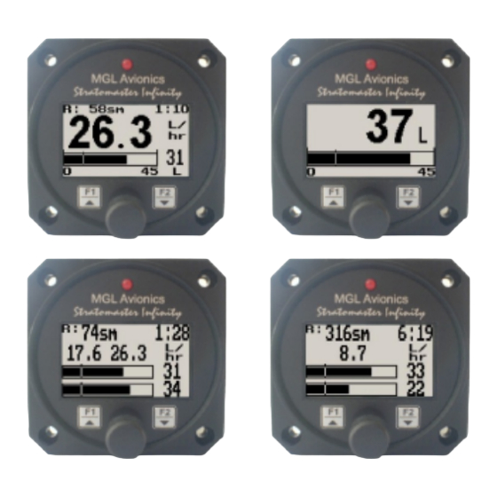
Page 2: Main Displays
3 Main Displays The FF-1 has 17 different modes of operation. The display modes can be selected in the fuel setup menu by selecting different configurations of the number of fuel flow/level senders installed. The FF-1 will automatically adjust the display... - Page 3 FF-1 Operating Manual Page 3 3.1 Single fuel flow and calculated tank level (single tank) Single fuel flow and fuel level sender (single tank) Differential fuel flow and calculated tank level (single tank) Differential fuel flow and fuel level sender (single tank)
- Page 4 FF-1 Operating Manual Page 4 3.2 Dual fuel flow and calculated tank levels (dual tank) Dual fuel flow and dual fuel level senders (dual tank) Fuel flow 2 Fuel range value Fuel endurance hours:minutes Fuel flow 1 value Fuel flow unit...
- Page 5 FF-1 Operating Manual Page 5 3.5 Dual fuel flow indicator This mode is displayed if both fuel flow 1and fuel flow 2 are selected and the fuel mode is selected for dual flow. Both fuel level senders are disabled. Fuel flow 1...
- Page 6 FF-1 Operating Manual Page 6 3.8 Differential/Summed fuel flow This mode is displayed if both fuel flow 1 and fuel flow 2 are selected and the fuel mode is selected for either differential or summed. Differential (fuel flow 1 minus fuel flow 2)
-
Page 7: Menu System
4 Menu System Pressing the rotary control button during the normal display mode will cause the FF-1 to enter the menu system. Use the up/down keys or the rotary control to navigate through the menu system. Note: (“ADC Values” menu item is only visible when powering up the unit and pressing the rotary control). -
Page 8: Display Setup
Select this menu option to adjust the display contrast. Select this menu option to turn the backlight on or off. Select your preferred language for the FF-1. English or French. 4.4 Fuel Setup This menu will customize itself to the various options you choose. The full fuel setup menu is shown. - Page 9 The K-Factor is the number of pulses generated by the fuel flow sender for one liter of fuel. The dual range fuel flow sender supplied by MGL Avionics has a K-Factor of 7000 in the low flow mode (jet installed) and 1330 for the high flow mode (no jet installed). The Flowscan 201A-6 has a K-Factor of 8454.
- Page 10 Select if fuel tank 1 has a physical fuel level sender connected to it or if the FF-1 must use a calculation based virtual fuel tank. If you do not want any fuel level information then set this parameter to off.
- Page 11 FF-1 Operating Manual Page 11 4.4.1 Calibrating the fuel level senders The fuel level sender needs to be calibrated before it can be used with this system. The calibration allows the system to learn the shape of your tank as well as any errors your fuel level sender or installation has.
- Page 12 If you do not know the cause of your error it is best to start from scratch. It should be remembered that accuracy in the fuel tank calibration is extremely important to enable your FF-1 to display the correct data.
-
Page 13: Loading Factory Default Settings
8 RS232 NMEA enabled GPS receiver message The Infinity FF-1 has the ability to be connected to a NMEA enabled RS232 GPS receiver to allow the FF-1 to use the actual ground speed in determining the fuel range. For this calculation, your current remaining fuel, your current fuel flow and the ground speed information are taken into account. -
Page 14: Installation
11.1 Connection Diagram The use of an external 1A fuse is recommended. Connect the supply terminals to your aircrafts power supply. The FF-1 can be used on both 12V and 24V without the use of any pre-regulators. Ensure that the supply voltage will not drop... - Page 15 11.2 Fuel flow sender installation The fuel flow sender allows the FF-1 to provide instantaneous readouts of hourly fuel usage, and both time and distance estimates on remaining fuel in flight. You can also verify the performance of your fuel pump during the pre-takeoff engine run up –...
- Page 16 30 liters per hour. This would apply to most small two and four stroke engines. The FF-1 is shipped with the fuel flow sender calibration set for the jet installed. In a good installation you can expect about +/- 3% maximum flow reading error with this factor.
- Page 17 Using other Flow Senders It is quite possible to use flow senders other than the MGL Avionics fuel flow sender. In this case ensure that the sender outputs a 5V TTL square wave or a similar signal. The FF-1 interface electronics will adapt to a variety of different voltages and pulse shapes as it contains a Schmitt-trigger input stage.
- Page 18 GPH), divided by 10, is written on a label attached to sensor. Multiply this number on the label by 10, which should give a value of approximately 32,000. The FF-1 requires a litre per hour K factor. Take the gallon per hour K factor, and divide it by 3.785 (which yields a K-Factor of approximately 8454).
- Page 19 In particular, select a model that does not have any metal parts that can rust. The FF-1 can interface to a large variety of these fuel level senders. It does not matter if the sender resistance increases or decreases with the fuel level as long as it changes.
- Page 20 After you have connected the system as shown below you can proceed to set up the system. (don’t forget that you need a connection from the FF-1 ground terminal to the engine block (at the same potential as the battery negative).
-
Page 21: Cable Connections
FF-1 Operating Manual Page 21 11.5 Cable connections DB 9 Pin Color Function Black Ground Orange Fuel level 1 sender Green Fuel level 2 sender RCA (Inner cable) Airtalk communication Used for firmware upgrading and airtalk speed message (ASI-1/ASX-1) Blue... - Page 22 FF-1 Operating Manual Page 22 Stratomaster Infinity Other instruments in the series ALT-1 Precision encoding altimeter and vertical speed indicator ALT-2 Precision encoding altimeter and vertical speed indicator with a serial RS232 transponder output ASI-1 Airspeed indicator (ASI) with automatic flight log...
Need help?
Do you have a question about the FF-1 and is the answer not in the manual?
Questions and answers