Advertisement
Quick Links
Introduction
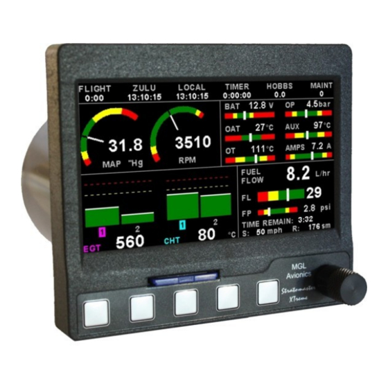
The XTreme-EMS is a compact universal engine monitoring system. The XTreme-EMS, which fits a standard 3 1/8"
(80mm) instrument panel hole, contains all the necessary functionality to replace several engine monitoring instruments.
All information is displayed in an easy to read format on a high resolution wide viewing angle 4.3" 1000cd/m2 sunlight
readable color display.
All engine sensors are connected to a RDAC (Remote data acquisition unit) which is normally mounted behind the firewall
of the aircraft and then just a simple CAN communication link is necessary to connect the XTreme-EMS to the RDAC.
The XTreme-EMS light weight, small size and high level of functionality makes it an excellent choice for all types of non-
certified aircraft.
XTreme - EMS
Universal Engine Monitoring System
Operating Manual – English 2.05
Advertisement

Related Manuals for MGL Avionics XTreme - EMS


Summary of Contents for MGL Avionics XTreme - EMS
- Page 1 XTreme - EMS Universal Engine Monitoring System Operating Manual – English 2.05 Introduction The XTreme-EMS is a compact universal engine monitoring system. The XTreme-EMS, which fits a standard 3 1/8” (80mm) instrument panel hole, contains all the necessary functionality to replace several engine monitoring instruments.
- Page 2 XTreme-EMS Operating Manual Page 2 1 Features • 4.3” high resolution 480x272, sunlight readable, wide viewing angle, 1000cd/m2 TFT LCD display • LED backlight (brightness can be adjusted for low light flying conditions) • Fits standard 3 1/8” (80mm) aircraft instrument panel hole •...
- Page 3 2x Auxiliary analog channel displays which are universal and can be configured to measure Pressure, Temperature or Current • Current measurement requires a MGL Avionics Closed Loop Current Sensor • Pressure can be measured using standard automotive resistive senders (e.g. VDO 2, 5 and 10Bar), Rotax 4-20mA senders as well as voltage output pressure senders (e.g.
- Page 4 XTreme-EMS Operating Manual Page 4 Current • Uses the MGL Avionics Closed Loop Current Sensor to measure the aircrafts current load. • Records maximum and minimum current reached in permanent memory UL Power ECU Display • Displays engine information from the UL Power ECU (Engine Control Unit) via the RS232 port •...
- Page 5 XTreme-EMS Operating Manual Page 5 2 XTreme-EMS Layout 4.3” high resolution (480x2720, Sunlight readable, wide viewing 2.1 Front layout Angle, 1000cd/m2 LCD display Rotary control. Press to access the quick SD card slot select menus and main menu Press for the previous display screen Press to advance to the Press to display the EGT...
- Page 6 XTreme-EMS Operating Manual Page 6 3 Display Screens Press the left or right most soft keys to cycle through the display screens. EMS DISPLAY GPS DISPLAY (External GPS receiver required) CHECKLIST / INFORMATION DISPLAY...
- Page 7 XTreme-EMS Operating Manual Page 7 3.1 EMS Display 3.1.1 Information bar FLIGHT: The flight time is automatically reset to zero when a new flight is started (manual or automatic flight detection). The “:” will flash when a flight is active. The flight timer can be started in the quick select menu (Manual flight mode). ZULU: GMT or Zulu time display.
- Page 8 XTreme-EMS Operating Manual Page 8 A maximum of 999 hours can be entered as a maintenance interval. A reminder message will appear on startup when zero hours are remaining. The reminder message will automatically disappear after 10 seconds or if the pilot presses any key. Engine running time for the purpose of the maintenance timer is defined as the run time where the engine RPM is greater than the “HOBBS MINIMUM RPM”...
- Page 9 XTreme-EMS Operating Manual Page 9 3.1.2.1 Magneto Check Function Activate the magneto check function in the sub-menu once you have reached your normal run-up RPM. The display will show the RPM deviation from when the magneto function was activated. Any RPM drops will be displayed as a negative RPM value, a positive reading indicates an increase in RPM.
- Page 10 XTreme-EMS Operating Manual Page 10 3.1.4.2 Dual fuel flow and calculated tank levels (dual tank) Dual fuel flow and dual fuel level senders (dual tank) 3.1.4.3 Single fuel flow and dual fuel level senders (dual tank) Single fuel flow, single fuel level sender, single calculated tank Differential fuel flow and dual fuel level senders (dual tank) Differential flow, single fuel level sender, single calculated tank Summed fuel flow and dual fuel level senders (dual tank)
- Page 11 XTreme-EMS Operating Manual Page 11 3.1.4.6 Dual fuel flow indicator This mode is displayed if both fuel flow 1 and fuel flow 2 is selected and the fuel mode is selected for dual flow. Both fuel level senders are disabled. 3.1.4.7 Single tank level indicator This mode is displayed if either fuel level 1 or fuel level 2 is selected.
- Page 12 XTreme-EMS Operating Manual Page 12 3.1.4.10 Calculated Fuel Tanks Calculated fuel tanks will have the text “CALC” in the fuel bar to indicate that the fuel level is calculated from fuel flow and that it is not a physical measure of the fuel tank. 3.1.4.11 Fuel Pressure The fuel pressure bar will be displayed when the fuel pressure has been enabled in the menu system.
- Page 13 XTreme-EMS Operating Manual Page 13 3.1.5 EGT / CHT display section The XTreme supports up to 12 thermocouples for EGT / CHT. The EGT / CHT section will automatically try and maximize the display area according to the number of EGT / CHT selected. The EGT / CHT parameters can be configured in the “EGT SETUP”...
- Page 14 XTreme-EMS Operating Manual Page 14 3.2 EMS Quick Select Menu System Press the rotary control when the EMS screen is displayed to access the EMS quick select menu. START FLIGHT: Select this option to manually start/stop a flight. This menu option is only shown if the XTreme-EMS is setup to select the manual flight option under the “FLIGHT LOG”...
- Page 15 XTreme-EMS Operating Manual Page 15 LEAN MODE: EGT information is also very useful for fuel mixture control. As the fuel mixture is leaned, so the exhaust gasses get hotter. This rise in temperature is a sign of increased combustion efficiency as the optimum mixture setting is approached. If the leaning progresses past a certain point however, the temperature will begin to drop.
- Page 16 XTreme-EMS Operating Manual Page 16 TIMER: Select this menu option to configure the timer. Use the rotary control to adjust the timers reset value. Press the “UP/DOWN” soft key to select whether the timer must count up or down, the “START/STOP” soft key to start or stop the timer and the “ON/OFF”...
- Page 17 XTreme-EMS Operating Manual Page 17 3.3 GPS Display (External RS232 GPS receiver required) The GPS page show the GPS information in an easy to read format. Sunrise/sunset times as well as the magnetic variation is shown. 3.4 GPS Quick Select Menu System Press the rotary control when the GPS screen is shown to access the GPS quick select menu.
- Page 18 XTreme-EMS Operating Manual Page 18 3.5 Information/Checklist Display The Information / Checklist page shows checklists and graphic information pages which are loadable from the SD card. The last checklist or graphic information page is automatically loaded as startup. 3.5.1 Graphic information pages The graphic information page allows you to display any type of image on the XTremes high resolution graphics display.
- Page 19 XTreme-EMS Operating Manual Page 19 3.5.2 Checklists A checklist file is simply a text file created in a word processing program and saved with a .ECL extension. The name of the file does not matter but we suggest calling it something familiar so you can easily identify it. The length of each text line must not be more then 60 characters and must be terminated with an Enter (CR).
- Page 20 XTreme-EMS Operating Manual Page 20 4 Main Menu System To access the main menu system, press the rotary control knob, scroll down to the “MENU” option and press the rotary control knob again. Use the rotary control to navigate the menu system.
- Page 21 XTreme-EMS Operating Manual Page 21 4.2 Flight Log NOTE: The Flight log is stored in RAM and is updated every minute. If the power is turned off to the XTreme-EMS before the flight has ended then the flight information after the last minute update will be lost. EXPORT FLIGHT LOG TO SD CARD : Use this function to export the current flight logs stored in the XTreme-EMS to a SD card.
- Page 22 XTreme-EMS Operating Manual Page 22 The XTreme uses the following algorithm to determine if a flight is in progress ( “AUTOMATIC” mode): If the ground speed is greater than the preset “FLIGHT DETECT MIN GROUND SPEED” value or the RPM 1 & 2 is greater than the preset “FLIGHT DETECT MINIMUM RPM1 2”...
- Page 23 XTreme-EMS Operating Manual Page 23 4.3 EMS Setup...
- Page 24 XTreme-EMS Operating Manual Page 24 4.3.1 RPM 1 Setup RPM DISPLAY: Select if you want the RPM to be displayed in “RPM” or “PERCENT” .If you do not want any RPM information then set this parameter to "OFF". If the rotor RPM is set to "RPM" or "PERECENT" then the engine RPM display will automatically be enabled.
- Page 25 XTreme-EMS Operating Manual Page 25 PULSES/REV: Enter the number of pulses per RPM. For engines with an uneven number of cylinders like three cylinder four stroke engines you can enter values containing fractions (usually 1.5 in this example). Most four stroke engines would generate one pulse for every two revolutions per cylinder.
- Page 26 XTreme-EMS Operating Manual Page 26 4.3.2 RPM 2 Setup RPM DISPLAY: Select if you want the RPM 2 to be displayed in “RPM” or “PERCENT” .If you do not want any RPM 2 information then set this parameter to off. If the RPM 2 is set to "RPM" or "PERECENT" then the engine RPM display will automatically be enabled.
- Page 27 XTreme-EMS Operating Manual Page 27 LABEL: Enter a label to suit your RPM 2 channel so you can identify it easily. POSITION: Select which side of the analog dials the RPM 1 / RPM 2 must be displayed on. Style Select this menu option to change the graphic style of the RPM 1 and RPM 2 display.
- Page 28 XTreme-EMS Operating Manual Page 28 4.3.3 EGT/CHT Setup EGT / CHT CHANNELS: Select the number of EGT or CHT channels you want to use. Choices are from 1 to 12. The temperature display will configure itself to make best possible use of the available display size. Please note that the minimum number of EGT & CHT channels that can be displayed is 1 and the maximum number of EGT and CHT channels that can be displayed is EGT / CHT DISPLAY MAX: Select the maximum temperature that you want the EGT/CHT bargraph to show.
- Page 29 Select if you are using a K-type, J-type or E-type thermocouple probe for the EGT/CHT group. All probes supplied by MGL Avionics are K-Type. J-types are sometimes used with American made CHT probes. All EGT probes are K-type. E- type probes are seldom used.
- Page 30 The K-Factor is the number of pulses generated by the fuel flow sender for one liter of fuel. The dual range fuel flow sender supplied by MGL Avionics has a K-Factor of 7000 in the low flow mode (jet installed) and 1330 for the high flow mode (no jet installed).
- Page 31 XTreme-EMS Operating Manual Page 31 Fuel level setup. (Only tank 1 setup is shown, follow the same steps for tank 2 setup) TANK 1 / TANK 2: Select if the fuel tank has a physical fuel level sender connected to it or if the Xtreme must use a calculation based virtual fuel tank.
- Page 32 XTreme-EMS Operating Manual Page 32 Adjusting calibration points automatically Select “SENDER” for the “MODE” menu item. Once you have installed a fuel level sender into your tank, make sure the float can travel all the way from empty to full position without hindrance of any kind. The calibration procedure should be carried out with your aircraft in flight attitude.
- Page 33 XTreme-EMS Operating Manual Page 33 Adjusting calibration points manually You may want to set individual calibration points manually. For example you may find that your fuel level over reading at a specific fuel level. Correcting the tank level reading for this area can be simply done by adjusting calibration point.
- Page 34 XTreme-EMS Operating Manual Page 34 FUEL PRESSURE SETUP: (MGL Avionics RDAC-XF / MAP Required) Select this menu item to setup the fuel pressure input. FUEL PRESSURE DISPLAY: This enables or disables the fuel pressure display on the EMS display screen TYPE: Select if you are using a resistive, voltage or a current output pressure sender.
- Page 35 XTreme-EMS Operating Manual Page 35 Pressure @ 20mA: Enter the pressure specified at 20mA output. Menu options for all sender types If the “USER" pressure sender is selected CALIBRATE SENDER: If the sender type is set to “USER”, then use this menu option to calibrate your pressure sender. See section 4.4.9 for more information.
- Page 36 XTreme-EMS Operating Manual Page 36 4.3.5 Manifold Setup (MGL Avionics RDAC-XF MAP required) MAP DISPLAY: This enables or disables the manifold pressure display on the EMS displays screens MAP UNIT: Select if you want the manifold pressure displayed in mB (millibars) or “Hg (inches of mercury).
- Page 37 XTreme-EMS Operating Manual Page 37 FILTER: This function can be used to select the signal filter time constant. Selections are "NONE", “FAST” or “SLOW”. This selection influences the rate at which your manifold pressure can change its reading. MAP CALIBRATION FACTOR: The sender in the RDAC is shipped uncalibrated.
- Page 38 XTreme-EMS Operating Manual Page 38 4.3.6 Oil Temperature Setup OIL TEMPERATURE DISPLAY: This enables or disables the oil temperature display SENDER: Select what type of sender you are using. Select “VDO 120C” or "VDO 150C" for a VDO resistive sender, “WESTACH” for Westach thermistor type senders, “MGL”...
- Page 39 XTreme-EMS Operating Manual Page 39 TEMPERATURE UNIT: Select whether you want the temperature to be displayed in degrees Celsius (ºC) or in degrees Fahrenheit (ºF). DISPLAY MAX: Select the maximum temperature that you want the oil temperature bargraph to show. This can give you increased display resolution.
- Page 40 XTreme-EMS Operating Manual Page 40 4.3.7 Oil Pressure Setup OIL PRESSURE DISPLAY: This enables or disables the oil pressure display TYPE: Select if you are using a resistive, voltage or current output pressure sender. If the “RESISTIVE” pressure sender is selected SENDER: Select what type of resistive pressure sender you are using.
- Page 41 XTreme-EMS Operating Manual Page 41 Pressure @ 4mA: Enter the pressure specified at 4mA output. Pressure @ 20mA: Enter the pressure specified at 20mA output. Menu options for all sender types If the “USER" pressure sender is selected CALIBRATE SENDER: If the sender type is set to “USER”, then use this menu option to calibrate your pressure sender.
- Page 42 XTreme-EMS Operating Manual Page 42 4.3.8 Auxiliary Analog 1, 2 Setup The analog AUX 1,2 channels on the RDAC are general purpose channels that can be used for pressure, temperature or current. FUNCTION: Select the function for the analog channel. Options are “PRESSURE”, “TEMPERATURE”, “CURRENT” or “OFF”. If the “PRESSURE”...
- Page 43 XTreme-EMS Operating Manual Page 43 If the “VOLTAGE” pressure sender is selected Sender: Select the type of voltage sender you are using. Select “UMA” for UMA senders, "0.5-4.5V" for voltage senders, or “USER” for a custom voltage sender. Model: For UMA senders select the UMA model number. If the “CURRENT”...
- Page 44 XTreme-EMS Operating Manual Page 44 HIGH CAUTION: Enter the pressure value for the high caution. This is the lower value of the upper yellow band. LOW CAUTION: Enter the pressure value for the low caution. This is the upper value of the lower yellow band. LOW ALARM: This enables or disables the pressure low alarm.
- Page 45 XTreme-EMS Operating Manual Page 45 Menu options for all sender types LABEL: Enter a label to suit your temperature channel so you can identify it easily. TEMPERATURE UNIT: Select whether you want the temperature to be displayed in degrees Celcius (ºC) or in degrees Fahrenheit (ºF). DISPLAY MAX: Select the maximum temperature that you want the bargraph to show.
- Page 46 ZERO CURRENT SENSOR: Select this function to indicate to the Xtreme-EMS that zero current is flowing through the MGL Avionics Closed Loop Current sensor. This is best done with the MGL Closed Loop Current sensor disconnected from the main current supplying conductor.
- Page 47 XTreme-EMS Operating Manual Page 47 4.3.10 Volts Setup VOLTS DISPLAY MAX: Select the maximum value that you want the volts bargraph in the EMS display to show. This can give you increased display resolution. VOLTS DISPLAY MIN: Select the minimum value that you want the volts bargraph in the EMS display to show. This can give you increased display resolution.
- Page 48 ZERO CURRENT SENSOR: Select this function to indicate to the Xtreme-EMS that zero current is flowing through the MGL Avionics Closed Loop Current sensor. This is best done with the MGL Closed Loop Current sensor disconnected from the main current...
- Page 49 Adjust the gain factor until the current is reading correctly. It will be best if a multimeter can be inserted in series with the current supplying conductor and the gain calibration adjusted until the Xtreme-EMS matches that of the multimeter. Please see the MGL Avionics Closed Loop Current Sensor documentation for more information.
- Page 50 XTreme-EMS Operating Manual Page 50 4.3.12 OAT Setup OAT DISPLAY: Select to enable or disable the OAT display. OAT TEMPERATURE UNIT: Select whether you want the OAT to be displayed in degrees Celsius (ºC) or in degrees Fahrenheit (ºF). OAT DISPLAY MAX: Select the maximum temperature that you want the OAT bargraph in the EMS display to show.
- Page 51 Select the ECU that is connected to the Xtreme-EMS. Select “NONE” for standard functionality, “ROTAX 912is” or “UL POWER”. 4.3.13.1 ROTAX 912IS Setup (MGL Avionics RDAC CAN required) The Rotax ECU transmits various status messages. These can be observed in the Rotax ECU status and Rotax ECU...
- Page 52 XTreme-EMS Operating Manual Page 52 The Xtreme-EMS must be setup as follows: RPM 1: PULSES/REV: 1.0 Fuel Flow: K-FACTOR 1: 3500 MODE: FLOW SENDER Manifold Air Pressure: No change needed Oil Pressure: TYPE: Resistive SENDER: User CALIBRATE SENDER: POINTS: 2 DISPLAY 1: 0.0 bar ADC 1: 0000 DISPLAY 2: 10.0 bar...
- Page 53 4.3.13.2 UL Power ECU Setup Connect the UL Power Engine to the XTreme-EMS using the RS232 port 1. The MGL Avionics RDAC can be used to measure CHT, EGT and MAP. The Xtreme-EMS also supports the UL Power Aux box.
- Page 54 XTreme-EMS Operating Manual Page 54 UL Power recommended settings: Oil Pressure : max 8 bar (115psi) - normal 2 to 5 bar (30 – 75 psi) above 2000rpm - minimum 0.7 bar Oil Temperature: Max 120°C (248°F) - Min 50°C (122°F) - Normal between 80°C and 100 °C (175°F – 212°F) Fuel Pressure: max 3.8 bar (55psi) - normal 3 bar (43,5 psi) - minimum 2.4 bar (35 psi) MAP: Max 1.1 bar (33 inch/kg) –...
- Page 55 XTreme-EMS Operating Manual Page 55 4.4 GPS Setup GPS: Select “OFF” to disable the GPS information screen or select "EXTERNAL" if you have an external NMEA compatible GPS connected to the XTreme-EMS. If an external GPS is used then it must output the following NMEA sentences •...
- Page 56 XTreme-EMS Operating Manual Page 56 4.5 Timers Setup SET UTC DATE & TIME: Use the rotary control to set the UTC date & time in the internal RTC. UTC OFFSET: Enter the UTC offset for your location. The UTC offset can be adjust in half an hour increments. SET HOBBS TIME: This function allows you to set the engine Hobbs meter to any value.
- Page 57 XTreme-EMS Operating Manual Page 57 CHANGE HOBBS CODE: This menu option allows you to change the Hobbs access code. You will first be prompted to enter the current code followed by entering in a new code followed by re-entering the new code. If the new code and the re-entered code is the same, then the Hobbs access code will be changed.
- Page 58 XTreme-EMS Operating Manual Page 58 4.6 Data Recording Setup The XTreme-EMS has the ability to act as a black box recorder, recording flight data directly onto an inserted SD card for later playback and investigation. Data is logged to s SD card in a Comma Separated Values (.CSV) file that can easily be opened in a spreadsheet or text viewer type program.
- Page 59 XTreme-EMS Operating Manual Page 59 Analog Channel 1: Pressure in psi Temperature in Degrees C Current in A Analog Channel 2 Type: 0=Off 1=Pressure 2=Temperature 3=Current Analog Channel 2: Pressure in psi Temperature in Degrees C Current in A Analog 3 Channel Type: 0=Off 1=Pressure 2=Temperature...
- Page 60 XTreme-EMS Operating Manual Page 60 TC12: Thermocouple channel 12 in Degrees Celsius Fuel Flow 1: Fuel Flow 1 in Liters per Hour Fuel Flow 2: Fuel Flow 2 in Liters per Hour Fuel Level 1: Fuel Level 1 in Liters Fuel Level 2: Fuel Level 2 in Liters Fuel Pressure:...
- Page 61 XTreme-EMS Operating Manual Page 61 4.7 Miscellaneous Setup AIRCRAFT REGISTRATION: Enter your aircraft registration. A maximum of 8 characters can be entered. The aircraft registration is displayed on the start up (Splash) screen. SAVE SETTINGS TO SD CARD: Select this option to save all the XTreme-EMS settings to the SD card. This is useful when setting up the instrument on the PC simulator and then later transferring the settings on the instrument itself.
- Page 62 XTreme-EMS Operating Manual Page 62 INFORMATION: This displays information about the Xtreme-EMS unit. 4.8 ADC Values These values are mainly used for debugging purposes.
- Page 63 XTreme-EMS Operating Manual Page 63 5 Startup (Splash) Screen Creating your own Startup (Splash) Screen: You will need: ·A bitmap picture of your choice (*.BMP, 480x272 pixel resolution) ·The BMP to MIF converter tool (can be downloaded free of charge from http://www.mglavionics.co.za or can be found on the XTreme SD card).
- Page 64 XTreme-EMS Operating Manual Page 64 6 Loading factory default settings Press and hold the left and right most soft keys simultaneously on power up to load default factory settings. The following message will be displayed: 7 Alarm condition If an alarm condition occurs the following will happen: •...
- Page 65 XTreme-EMS Operating Manual Page 65 9 Specifications Operating Temperature Range -10ºC to 50ºC (14ºF to 122ºF) Storage Temperature Range -20ºC to 80ºC (-4ºF to 176ºF) 8 to 30Vdc SMPS (switch mode power supply) Power Supply Built in 33V over voltage and reverse voltage protection Current Consumption Approx.
- Page 66 XTreme-EMS Operating Manual Page 66 10 Installation 10.1 Connection Diagram The use of an external 1A fuse is recommended. Connect the supply terminals to your aircraft’s power supply. The XTreme-EMS can be used on both 12V and 24V without the use of any pre-regulators. Ensure that the supply voltage will not drop below 8V during operation as this may result in incorrect readings.
- Page 67 No Connection NC = Not Connected The XTreme-EMS has a D15 Female connector. The connecting cable must have a D15 male connector attached to it. 10.3 MGL Avionics RDAC-XF, RDAC-XF MAP and RDAC-XG RDAC-XF / RDAC-XF (MAP) RDAC-XG Please see the RDAC-XF / RDAC-XG documentation for installation and usage.
- Page 68 XTreme-EMS Operating Manual Page 68 10.3.1 Connecting the RDAC-XF / RDAC-XG / RDAC-CAN to the Xtreme-EMS Observe the polarity of the two CAN wires. One of the lines is called “CAN L” and the other “CAN H”. It is recommended that a twisted pair wire is used for this connection using two wire colors for ease of identification.
- Page 69 XTreme-EMS Operating Manual Page 69 11 Firmware upgrades The XTreme-EMS firmware can be upgraded in the field to the latest version via the SD card. This will keep your XTreme- EMS up to date with bug fixes and new features. The name of the firmware file must be called XTREME.FW and it must reside in the root directory of the SD card.
- Page 70 XTreme-EMS Operating Manual Page 70 12 Dimensions 12.1 Front view...
- Page 71 XTreme-EMS Operating Manual Page 71 12.2 Side view (Version 1) 12.3 Top view (Version 1)
- Page 72 XTreme-EMS Operating Manual Page 72 12.4 Side view (Version 2) 12.5 Top view (Version 2)
- Page 73 IMPORTANT NOTICE: You must make your own determination if the products sold by MGL Avionics are safe and effective for your intended applications. MGL Avionics makes no representations or warranties as to either the suitability of any of the products we sell as to your particular application or the compatibility of any of the products we sell with other products you may buy from us or anywhere else, and we disclaim any warranties or representations that may otherwise arise by law.
Need help?
Do you have a question about the XTreme - EMS and is the answer not in the manual?
Questions and answers