Advertisement
Quick Links
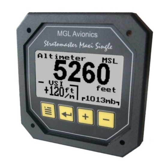
Stratomaster Maxi Single
ALT-3, ALT-4, ALT-5
ALT-3: Wide range precision aviation altimeter
ALT-4: Encoding altimeter with Gillman code transponder output
ALT-5: Encoding altimeter with serial output, compatible with
IIMorrow, Garmin/Trimble or MGL RS232 protocols.
The ALT-3 altimeter is a 3.5" instrument that can be used as absolute or relative altimeter.
In addition, it offers a wide range VSI (vertical speed) indicator as standard option.
ALT-4 and ALT-5 models include a gillman code and serial transponder interface.
The altimeter conforms to ANSI standard atmosphere rules from –700 ft up to a minimum of
40.000 ft. Accuracy is ensured by thermal compensation of the laser trimmed pressure sensor.
High resolution is made possible by stable and sensitive electronics.
The altimeter can display altitude in feet or meters, local pressure can be set in millibars or inches
or mercury.
Advertisement

Subscribe to Our Youtube Channel
Related Manuals for MGL Avionics Stratomaster Maxi Single ALT-3


Summary of Contents for MGL Avionics Stratomaster Maxi Single ALT-3
- Page 1 Stratomaster Maxi Single ALT-3, ALT-4, ALT-5 ALT-3: Wide range precision aviation altimeter ALT-4: Encoding altimeter with Gillman code transponder output ALT-5: Encoding altimeter with serial output, compatible with IIMorrow, Garmin/Trimble or MGL RS232 protocols. The ALT-3 altimeter is a 3.5” instrument that can be used as absolute or relative altimeter. In addition, it offers a wide range VSI (vertical speed) indicator as standard option.
- Page 2 Absolute mode / Relative mode Reference altitude Absolute mode: Altitude relative to sea level (MSL) Relative mode: Altitude relative to some other altitude Switching between absolute and relative modes is done using the “Enter” key when you see the main screen. As you switch from absolute to relative mode you can set the current altitude as the new reference altitude.
- Page 3 Contrast … This function allows you to change the display contrast to your liking. You can select values from about 20 to 45. (can vary depending on display type). Backlight … This function allows you to switch the display backlight on or off. The backlight is normally left on.
- Page 4 The electronic VSI generally has much less drift compared to a mechanical VSI and this function will only be used very occasionally. Ensure that you perform this function when no pressure changes due to wind or other reasons are occuring. It is normal for the VSI to show short, small positive or negative readings when your aircraft is standing still on the ground.
- Page 5 ALT+10500C+10500L1013+0000XBAcr The message starts with “ALT” followed by six characters altitude. The first character is either a “+” or “-“ if the altitude is negative. This altitude is relative to a local pressure of 1013mB. This is followed by the character “C” and a further six character altitude. This altitude is corrected for the current local pressure setting of the instrument.
- Page 6 Connecting the Gillman code transponder interface (ALT-4 only) The connection to the transponder consists of 10 or 11 connections, many transponders accept only codes A1 to C4, in this case you will leave signal D4 unconnected. This example shows the required connection to a Microair T2000 transponder.
- Page 7 Should you use the included D15 connector harness the layout of the signals on the grey ribbon cable is as follows: This signal is on the cable with the red marker band Ground Ground Ground Ground Ground The ALT-4 altimeter will measure altitudes typically to around 42000 ft, however, this requires a transponder that uses signal D4.
-
Page 9: Technical Specifications
We recommend that measures are taken to prevent voltage transients in excess of this limit. MGL Avionics recommends the fitment of a fuse in line with a 33V transorb (available from MGL Avionics at low cost) to protect electronic instruments, radios and intercom systems. Only one such arrangement is required for a cluster of instruments. - Page 10 The ALT-4 encoding altimeter is uncertified equipment and may normally only be used in uncertified aircraft, homebuilt aircraft and microlights (ultralights). Special operations permits for other aircraft may be required. Please be very aware that any wiring mistake related to the application of Gillman codes to your transponder will result in incorrect altitudes broadcast by your transponder.
- Page 11 Installing the ALT-3, 4 or 5 altimeter To other instruments Power Connect static port switch to suitable static line on aircraft. Fuse Positive supply Note: leaving this port (+12V from battery) unconnected may lead to altitude errors as cabin Negative supply pressure chages due to airflow or other factors (airframe ground)
- Page 12 Connect the supply terminals to your aircrafts power supply (you need a dropping resistor or pre- regulator for 24/28V systems). Without pre-regulator the voltage on the power supply connector should not exceed 18V. Internal protection will cause high current flow if voltage exceeds 33V as the instrument will attempt to dump excess voltage.
Need help?
Do you have a question about the Stratomaster Maxi Single ALT-3 and is the answer not in the manual?
Questions and answers