Advertisement
Quick Links
Advertisement

Subscribe to Our Youtube Channel
Related Manuals for MGL Avionics Stratomaster Enigma


Summary of Contents for MGL Avionics Stratomaster Enigma
- Page 1 Stratomaster Enigma Preliminary installation documentation...
-
Page 2: Electrical Installation
General This document describes the installation requirements for a single Enigma panel. This document is work in progress and still very incomplete. Please check on our website for any updates to the Enigma installation documentation. Electrical installation This image shows typical wiring for an Enigma panel. In this case a small backup battery is used. - Page 3 output. Maximum permitted current draw from these terminals is 0.5A. Under no circumstances connect transceivers or lighting to these terminals. Recommended backup battery types are 12V sealed lead acid with capacities ranging from 1Ah to 2.5Ah. In case of a dual panel installation, it is permissible to connect both panels to a single backup battery.
- Page 4 Install ferrite beads close to the source of interference. It does not help much if there is two meters of cable between source and ferrite bead. Distances as shown in the photo are correct. Multiple wires may share a single ferrite bead with the exception of the GPS aerial antenna which requires a ferrite on its own.
- Page 5 AOA port types Photo of an experimental single port AOA probe mounted next to the pitot tube on the wing strut of our Jora aircraft. This probe, made from wood, works very well indeed.
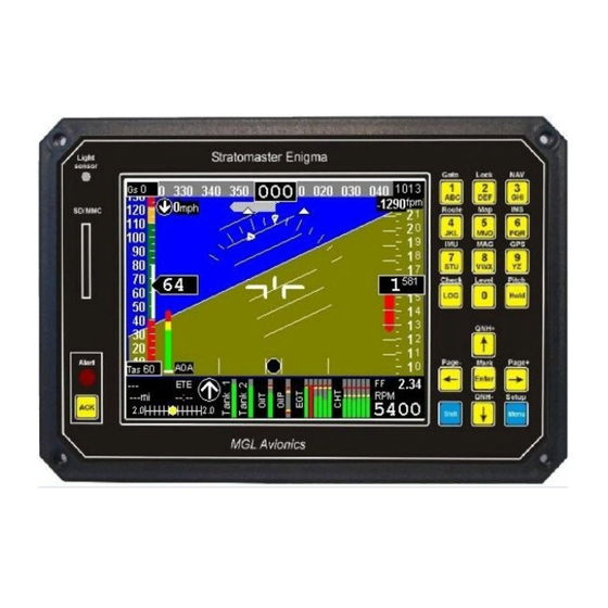
- Page 6 Ergonomical considerations Enigma contains a very advanced LCD display that is able to perform well in direct sunlight conditions. In order to achieve this and further ensure low power consumption, the display contains a “light director”. This focuses the major part of available light towards the viewer, creating a brighter image but also reducing the effect of ambient light falling at an angle onto the display surface.
- Page 7 Transponder interface wiring The transponder interface produces Gillman (Gray) coded altitude information suitable for connection to a mode C transponder. Connections using the standard code identifiers are shown here. If your transponder does not support signals D4 and D2, leave them unconnected. At least one of the ground wires should be connected to the corresponding ground terminal of your transponder.
- Page 8 Transponder connections for popular models...
- Page 9 Transponder interface wiring for Microair T2000 (ignore pin numbers on DB15 connector). Also line “Encoder power” is not used with Enigma.
Need help?
Do you have a question about the Stratomaster Enigma and is the answer not in the manual?
Questions and answers