Table of Contents
Advertisement
Quick Links
Advertisement
Table of Contents

Subscribe to Our Youtube Channel
Related Manuals for Westermo Lynx L210-F2G-EX


Summary of Contents for Westermo Lynx L210-F2G-EX
- Page 1 Lynx L210-F2G-EX Industrial Ethernet 10-port Switch...
- Page 2 6643-22601...
-
Page 3: General Information
Under no circumstances shall Westermo be responsible for any loss of data or income or any special, incidental, and consequential or indirect damages howsoever caused. -
Page 4: Safety And Regulations
Safety and Regulations Warning signs are provided to prevent personal injuries and/or damages to the product. The following levels are used: Level of warning Description Consequence Consequence personal injury material damage Indicates a potentially Possible death or Major damage to the hazardous situation major injury product... -
Page 5: Before Installation
WARNING - PROTECTIVE FUSE It must be possible to disconnect manually from the power supply. Ensure compliance to national installation regulations. Replacing the internal fuse must only be performed by Westermo qualified personell. WARNING - POWER SUPPLY CONNECTION There are safety regulations on which power sources that shall be used in conjunction with the product. - Page 6 WARNING - REDUCE THE RISK OF FIRE To reduce the risk of fire, use only telecommunication line cords with a cable diameter of AWG 26 or larger. Regarding power cable dimensions, see Interface Specifications. CAUTION - CLASS 1 LASER PRODUCT Do not look directly into a fibre optical port or any connected fibre, although the product is designed to meet the Class 1 Laser regulations and complies with 21 CFR 1040.10 and 1040.11.
-
Page 7: Product Disposal
If the product is used in a manner not according to specification, the protection provided by the equipment may be impaired. If the product is not working properly, contact the place of purchase, nearest Westermo distributor office or Westermo technical support. -
Page 8: Atex Certification
ATEX certification ATEX certification number Baseefa12ATEX0119X Standards EN 60079-0, EN 60079-15 Certification code Ex nA IIC T3 Gc (-40°C ≤ Ta ≤ +70°C) ATEX code II 3G Specific Conditions of Use The equipment must be installed in an area of not more than pollution degree 2 in accordance with IEC/EN 60664-1, and in an enclosure that provides a minimum degree of protection of at least IP54 and complies with the relevant requirements of EN 60079-0 and EN 60079-15. - Page 9 SFP option approved transceivers SFP Transceivers, 100 Mbit 1100-0131 MLC2, Multimode, LC-Connector, 2 km, 1310 nm 1100-0132 SLC20, Singlemode, LC-Connector, 20 km, 1310 nm 1100-0133 SLC40, Singlemode, LC-Connector, 40 km, 1310 nm 1100-0134 SLC80, Singlemode, LC-Connector, 80 km, 1550 nm 1100-0140 SLC120, Singlemode, LC-Connector, 120 km, 1550 nm BiDi Transceivers, 100 Mbit 1100-0145 SLC15-BiDi-A, Singlemode, BiDi, 20 km, 1310 nm TX, 1550 nm RX...
- Page 10 ATEX-Zertifizierung ATEX-Zulassungsnummer Baseefa12ATEX0119X Standards EN 60079-0, EN 60079-15 Zertifizierungscode Ex nA IIC T3 Gc (-40 °C ≤ Ta ≤ +70 °C) ATEX-Code II 3G Spezifische Einsatzbedingungen Die Geräte müssen in einem Bereich welcher einem maximalen Verschmutzungsgrad der Stufe 2 gemäß IEC/EN 60664-1 entspricht und in einem Gehäuse, das einen Schutzgrad von mindestens IP54 bietet und die relevanten Anforderungen von N 60079-0 und EN 60079-15 erfüllt, installiert werden.
- Page 11 Für SFP-Option zugelassene Transceiver SFP-Transceiver, 100 Mbit 1100-0131 MLC2, Multimode, LC-Anschluss, 2 km, 1310 nm 1100-0132 SLC20, Singlemode, LC-Anschluss, 20 km, 1310 nm 1100-0133 SLC40, Singlemode, LC-Anschluss, 40 km, 1310 nm 1100-0134 SLC80, Singlemode, LC-Anschluss, 80 km, 1550 nm 1100-0140 SLC120, Singlemode, LC-Anschluss, 120 km, 1550 nm BiDi-Transceiver, 100 Mbit 1100-0145 SLC15-BiDi-A, Singlemode, BiDi, 20 km, 1310 nm TX, 1550 nm RX 1100-0146 SLC15-BiDi-B, Singlemode, BiDi, 20 km, 1550 nm TX, 1310 nm RX...
- Page 12 Certification ATEX Numéro de certification ATEX Baseefa12ATEX0119X Normes EN 60079-0, EN 60079-15 Code de certification Ex nA IIC T3 Gc (-40°C ≤ Ta ≤ +70°C) Code ATEX II 3G Conditions spéciales d'utilisation L'équipement doit être installé dans une zone où le degré de pollution ne dépasse pas le degré...
- Page 13 Transmetteurs optionnels SFP certifiés Transmetteurs SFP, 100 Mbit 1100-0131 MLC2, multimode, connecteur LC, 2 km, 1310 nm 1100-0132 SLC20, monomode, connecteur LC, 20 km, 1310 nm 1100-0133 SLC40, monomode, connecteur LC, 40 km, 1310 nm 1100-0134 SLC80, monomode, connecteur LC, 80 km, 1550 nm 1100-0140 SLC120, monomode, connecteur LC, 120 km, 1550 nm Transmetteurs Bi-Di, 100 Mbit 1100-0145 SLC15 Bi-Di A, monomode, Bi-Di, 20 km, 1310 nm TX, 1550 nm, RX...
-
Page 14: Agency Approvals And Standards Compliance
Agency approvals and standards compliance Type Approval / Compliance EN 61000-6-1, Immproducty residential environments EN 61000-6-2, Immproducty industrial environments EN 61000-6-4, Emission industrial environments EN 50121-4, Railway signalling and telecommunications apparatus IEC 62236-4, Railway signalling and telecommunications apparatus Safety UL 62368-1, Safety Communication Technology Marine DNV GL rules for classification - Ships and offshore products EN 60079-0, EN 60079-15... -
Page 15: Declaration Of Conformity
Declaration of Conformity Hereby, Westermo declares that this product is in compliance with applicable EU directives. The full EU declaration of conformity and other detailed information is available at www.westermo.com/support/product-support. Description Lynx is an industrial switch made for harsh enviroments. The switch can be used in ether 100 Mbit or Gigabit networks due to our multi-rate SFP solution. -
Page 16: Hardware Overview
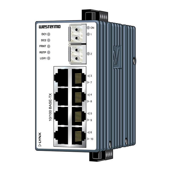
Hardware Overview Location of interface ports and LEDs LED Indicators Power connection SFP transceivers Ethernet connection TX (8 ports) Position Signale Direction Description Input/output values No.1 In/Out Transmitted/Received data No. 2 In/Out Transmitted/Received data No. 3 In/Out Transmitted/Received data Per port: No. -
Page 17: Interface Specifications
Interface specifications Power Operating voltage Rated: 24 to 48 VDC Operating: 19 to 60 VDC Rated current 240 mA @ 24 VDC 120 mA @ 48 VDC Rated frequency Inrush current, I 22.7·10 s @ 48 VDC Startup current* 2 x Rated current Polarity Reverse polarity protected Redundant power input... - Page 18 Tightening torque, screw flange 0.3 Nm Console Electrical specification TTL-level Data rate 115.2 kbit/s Data format 8 data bits, no parity, 1 stop bit, no flow control Circuit type SELV Connection 2.5 mm jack, use only Westermo cable 1211-2027 6643-22601...
-
Page 19: Sfp Transceivers
SFP Transceivers The product supports UL and IEC certified transceivers only. See Westermo's modular transceivers datasheets 100 Mbit and 1 Gbit for supported SFP transceivers, which can be downloaded from the product support pages at www.westermo.com/support/ productsupport. Each SFP slot can hold one SFP transceiver. See "Transceiver User Guide 6100-0000"... -
Page 20: Type Tests And Environmental Conditions
Type tests and environmental conditions Environmental phenomena Basic standard Description Test levels EN 61000-4-2 Enclosure Contact: ±6 kV Air: ±8 kV Fast transients EN 61000-4-4 Power port ±2 kV Signal ports Earth port ±1 kV Surge EN 61000-4-5 Power port L-E: ±2 kV, 42 Ω, 0.5 μF, 1.2/50 μs L-L: ±2 kV, 42 Ω, 0.5 μF, 1.2/50 μs L-E: ±2 kV, 12 Ω, 9 μF, 1.2/50 μs... -
Page 21: Connection To Console Port
The following steps needs to be taken 1. Connect the serial diagnostic cable to the console port (use only Westermo cable 1211-2027). 2. Connect cable to your computer (USB port, if drivers are needed they can be downloaded from our Web page). -
Page 22: Connector Information
Connector Information Power connection Product 4-position Direction Description Input values marking No. 1 +DC1 Input Supply voltage input DC1 = (19 - 60) VDC No. 2 +DC2 Input Supply voltage input DC2 = 240 mA @ 24 VDC No. 3 -COM Input Common... -
Page 23: Led Indicators
LED indicators Status Description Product has no power. GREEN All OK, no alarm condition. Alarm condition, or until product has start- ed up. (Alarm conditions are configurable, see ''WeOS Management Guide''). BLINK Location indicator ("Here I am!"). Activated when connected to IPConfig Tool, or upon request from Web or CLI. - Page 24 Mounting This product should be mounted on 35 mm DIN-rail, which is horizontally mounted inside an apparatus cabinet or similar. It is recommended that the DIN-rail is connected to ground. Snap on the product to the DIN-rail according to the figure. Mounting Lynx with integrated DIN-clip: Removal This product has an integrated DIN-clip.
-
Page 25: Getting Started
This product runs Westermo Operating System (WeOS) which provides several management tools that can be used for configuration of the product. • WeConfig tool This is a custom Westermo tool used for discovery of attached Westermo products. • Web Configuration of the product using the web browser. -
Page 26: Referring Documents
Referring documents Type Description Document number Management Guide Westermo OS management guide 6101-3201 Factory default on L210-F2G EX It is possible to set the product to factory default settings by using two straight standard Ethernet RJ-45 cables. 1. Power off the switch and disconnect all Ethernet cables (copper and fibre). - Page 27 Dimensions Measurements are stated in millimeters. 96 ±1 52 ±1 92 ±1 6643-22601...
- Page 28 Westermo • SE-635 35 Stora Sundby, Sweden Tel +46 16 42 80 00 Fax +46 16 42 80 01 E-mail: info@westermo.com www.westermo.com REV.I 6643-22601 2020-12 Westermo Network Technologies AB, Sweden...
Need help?
Do you have a question about the Lynx L210-F2G-EX and is the answer not in the manual?
Questions and answers
How to reset the switch? without connecting to the web
To reset the Westermo Lynx L210-F2G-EX switch to factory default settings without connecting to the web, follow these steps:
1. Power off the switch and disconnect all Ethernet cables (both copper and fiber).
2. Connect one Ethernet cable between Ethernet ports 3 and 10.
3. Connect another Ethernet cable between Ethernet ports 6 and 7.
4. Power on the switch.
5. Wait for the factory reset process to complete. The ON LED will flash RED initially and then turn solid GREEN when the reset is complete.
6. To skip the factory reset, simply wait for approximately 30 seconds after the ON LED starts flashing RED without unplugging the Ethernet cables.
Do not power off the switch during the reset process.
This answer is automatically generated