Dell PowerVault MD3000 Hardware Owner's Manual
Raid enclosure
Hide thumbs
Also See for PowerVault MD3000:
- Information update (94 pages) ,
- Update instructions (92 pages) ,
- Getting started manual (43 pages)

Related Manuals for Dell PowerVault MD3000


Summary of Contents for Dell PowerVault MD3000
- Page 1 Dell™ PowerVault™ MD3000 RAID Enclosure Hardware Owner’s Manual w w w . d e l l . c o m | s u p p o r t . d e l l . c o m...
-
Page 2: Notes, Notices, And Cautions
Reproduction in any manner whatsoever without the written permission of Dell Inc. is strictly forbidden. Trademarks used in this text: Dell, the DELL logo, PowerEdge, and PowerVault are trademarks of Dell Inc.; Microsoft, Windows, and MS-DOS are registered trademarks of Microsoft Corporation; Red Hat is a registered trademark of Red Hat Inc.; UNIX is a registered trademark of The Open Group in the United States and other countries. -
Page 3: Table Of Contents
........Enclosure Features Modular Disk Storage Manager Other Information You May Need Hardware Features . - Page 4 Virtual Disk Migration and Disk Roaming Advanced Features Storage Partitions Host Types ....... . .
- Page 5 Installing Enclosure Components Recommended Tools ....... Removing and Replacing the Front Bezel Removing and Installing Physical Disks Removing Physical Disks from the Enclosure Installing SAS Physical Disks in the Enclosure...
- Page 6 Obtaining Assistance Online Services AutoTech Service Automated Order-Status Service Support Service Dell Enterprise Training Problems With Your Order Product Information Returning Items for Warranty Repair or Credit Before You Call ........
-
Page 7: About Your System
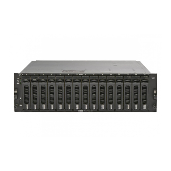
The Dell™ PowerVault™ MD3000 is a 3U rack-mounted external Redundant Array of Independent Disks (RAID) enclosure capable of accommodating up to 15 3.0-Gbps, Serial-Attached SCSI (SAS) disks. Connectivity between the RAID enclosure and the host server is provided by Dell SAS 5/E Host Bus Adapters (HBAs). -
Page 8: Modular Disk Storage Manager
The Getting Started Guide provides an overview of enclosure features, setting up your enclosure, and technical specifications. • Setting Up Your PowerVault MD3000 provides an overview of setting up and cabling your storage array. • The PowerVault MD3000 Installation Guide provides installation and configuration instructions for both software and hardware. -
Page 9: Hardware Features
Updates are sometimes included to describe changes to the enclosure, software, and/or documentation. NOTE: Always check for updates on support.dell.com and read the updates first because they often supersede information in other documents. • Release notes or readme files are included to provide last-minute updates to the enclosure or documentation or advanced technical reference material intended for experienced users or technicians. -
Page 10: Front-Panel Indicators And Features
Steady amber: Power is on and enclosure is in reset state. Steady blue: Power is on and enclosure status is OK. Flashing blue: Enclosure LED is being blinked by MD Storage Manager. Flashing amber: Enclosure is in fault state. - Page 11 Figure 1-2. Front-Panel Features enclosure status LED enclosure mode switch (unused) Table 1-2. Front-Panel Components Component Icon Enclosure status LED (blue/amber) Power LED (green) Split mode LED (green) power LED physical disks (15) Condition Steady amber: Power is on and enclosure is in reset state. Steady blue: Power is on and enclosure status is OK.
- Page 12 Table 1-2. Front-Panel Components (continued) Component Icon Enclosure mode switch NOTE: This system does not support user-customizable operating modes. Therefore, the split mode LED and enclosure mode switch are not functional. Physical Disk Carrier LED Indicators Each physical disk carrier in your enclosure has two LEDs: an activity LED (green) and a bicolor (green/amber) status LED (see Figure 1-3).
-
Page 13: Back-Panel Indicators And Features
Table 1-3. Physical Disk Carrier Status LEDs (continued) Status LED Green flashing On 400 ms Off 100 ms Amber flashing (125 ms) Flashing green, amber, and off Green 3 seconds, amber 3 seconds, and off 3 seconds Back-Panel Indicators and Features Figure 1-4 shows the back-panel features of the enclosure. - Page 14 One SAS Out port connector (not used) • Debug port (Dell support only) For a description of each component on the front panel of the RAID controller module, see Table 1-4. For an explanation of how to connect the enclosure using the RAID controller module ports, see "Cabling Your RAID Enclosure"...
- Page 15 Off: Ethernet connection is not active. Provide a 10/100 Mbps Ethernet connection for out-of-band management of the enclosure. Green: Ethernet connection is operating at 100BASE-T. Off: Ethernet connection is operating at 10BASE-T or is not active. Dell support only. Not used. About Your System...
-
Page 16: Cache Functions And Features
Write Through for all virtual disks. When the battery is replaced, Write Back is reenabled. The RAID controller module logs the age of the battery and issues a replacement reminder message approximately six weeks before expiration. After replacing the battery, you must use MD Storage Manager to reset the battery age. -
Page 17: Power Supply And Cooling Fan Features
Write-Back Cache Write-back cache is a caching strategy whereby write operations result in a completion signal being sent to the host operating system as soon as the cache receives the data to be written. The target physical disk will receive the data at a more appropriate time in order to increase controller performance. In dual- active controller configurations with write-back caching enabled, the write data is always copied to the cache of the second controller before completion status is issued to the host initiator. - Page 18 Figure 1-7. Power Supply and Cooling Fan Module LED Features and Indicators DC power LED cooling fans (2) Table 1-5. Power Supply/Cooling Fan Module LED Indicators Type Color DC power Green Power Amber supply/cooling fan fault AC power Green About Your System Power supply/cooling fan fault on/off switch Icon...
-
Page 19: Cabling Your Raid Enclosure
Cabling Your RAID Enclosure This section provides the following information: • Procedures for connecting your RAID enclosure to a host system • A description of redundant, nonredundant, and clustering configurations, including cabling diagrams for each Before You Begin Before connecting your RAID enclosure, ensure that the following are available: •... -
Page 20: Cabling The Enclosure
RAID controller module results in loss of host access to storage on the RAID enclosure. Redundancy is established by installing separate data paths between the host and the storage array, in which each path is to different RAID controller modules. Redundancy protects the host from losing access to data in the event of path failure, because both RAID controllers can access all the disks in the storage array. - Page 21 Figure 2-1. Cabling a Single Host Using Redundant Data Paths dual-HBA host server MD3000 RAID Enclosure single-HBA host server MD3000 RAID Enclosure Cabling Your RAID Enclosure...
-
Page 22: Nonredundant Configurations
Figure 2-3 through Figure 2-5 show two, three and four hosts, each connected to only one RAID controller module. The hosts can share storage space but without redundant paths, if one path were to fail, the server on that path would be disconnected from the storage array. - Page 23 Figure 2-3. Cabling Two Hosts with Nonredundant Data Paths Figure 2-4. Cabling Three Hosts with Nonredundant Data Paths single-HBA host server single-HBA host server MD3000 RAID Enclosure single-HBA host server single-HBA host server single-HBA host server MD3000 RAID Enclosure Cabling Your RAID Enclosure...
-
Page 24: Cluster Configurations
Figure 2-5. Cabling Four Hosts with Nonredundant Data Paths Cluster Configurations Figure 2-6 through Figure 2-8 show redundant, two-node cluster configurations using a single RAID enclosure. Cabling Your RAID Enclosure single-HBA host server single-HBA host server single-HBA host server single-HBA host server MD3000 RAID Enclosure... - Page 25 Figure 2-6. Cabling a Two-Node Cluster (Single HBA, Nonredundant Data Paths from each Node) Figure 2-7. Cabling a Two-Node Cluster (Single HBA, Redundant Data Paths from each Node single-HBA host server single-HBA host server MD3000 RAID Enclosure single-HBA host server single-HBA host server MD3000 RAID Enclosure Cabling Your RAID Enclosure...
- Page 26 Figure 2-8. Cabling a Two-Node Cluster (Dual HBA, Redundant Data Paths from each Node For a more detailed discussion of redundancy and nonredundancy, as well as alternate path software, see "Hardware Redundancy and Failover" on page 40. Cabling Your RAID Enclosure dual-HBA host server dual-HBA host server MD3000 RAID Enclosure...
-
Page 27: Using Your Raid Enclosure
255 virtual disks that can be assigned to hosts. Physical Disks Only Dell-supported 3.0-Gbps SAS physical disks are supported in the storage array. If the RAID controller module detects unsupported physical disks, it marks the disk as unsupported and the drive becomes unavailable for all operations. -
Page 28: Self-Monitoring Analysis And Reporting Technology (Smart)
The RAID controller monitors all attached drives and notifies users when a predicted failure is reported by a physical disk. Virtual Disks and Disk Groups When configuring a storage array, you would normally proceed in this order: • Organize the physical disks into disk groups. -
Page 29: Supported Raid Levels
Unconfigured capacity is comprised of the available physical disk space that is not already assigned in the storage array. Free capacity is the space in a disk group that has not been assigned to a virtual disk. -
Page 30: Raid 5
This leaves the remaining half of the physical disk capacity for actual storage. RAID 10 is automatically used when a RAID level of 1 is chosen with four or more physical disks. -
Page 31: Segment Size
128 KB. Hot Spares and Rebuild A valuable strategy to protect data is to assign available physical disks in the storage array as hot spares. A hot spare adds another level of fault tolerance to the storage array. -
Page 32: Rebuild
RAID software automatically attempts to rebuild the data to restore redundancy. If no hot spares are available, an automatic rebuild occurs when a new physical disk is installed. You can use MD Storage Manager to select a specific physical disk on which the rebuild should occur. -
Page 33: Virtual Disk Operations
NOTE: Dell recommends that you run data consistency checks on a redundant array at least once a month. This allows detection and automatic replacement of unreadable sectors. Finding an unreadable sector during a rebuild of a failed physical disk is a serious problem, since the system does not have the redundancy to recover the data. -
Page 34: Disk Group Operations
(RAID 0) by converting it to a RAID 5 set. Select the virtual disk that you want to change and select the type of RAID level to which you want to migrate. MD Storage Manager provides information about RAID attributes to assist you in selecting the appropriate level. You can perform a RAID level migration while the system is still running and without rebooting, which maintains data availability. - Page 35 (the segment size multiplied by the number of physical disks in the disk group used for data storage). In this case, multiple disks are used for the same request, but each disk is only accessed once. Virtual Disk Capacity Expansion When you configure a virtual disk, you select a capacity based on the amount of data you expect to store.
-
Page 36: Raid Background Operations Priority
NOTE: Setting a high priority level will impact storage array performance. It is not advisable to set priority levels at the maximum level. Priority should also be assessed in terms of impact to host access and time to complete an operation. -
Page 37: Advanced Features
To create a storage partition, you first define a host or host group, then define a host-to-virtual disk mapping. -
Page 38: Host Types
Not every operating system will have the same number of LUNs available for use. Host Types Generally, a host is a server that accesses a storage array, is mapped to the virtual disks, and uses one or more HBA ports. In general, hosts have the following attributes: •... -
Page 39: Snapshot Repository Virtual Disk
When you create a snapshot virtual disk, it automatically creates a snapshot repository virtual disk. A snapshot repository is a virtual disk created in the storage array as a resource for a snapshot virtual disk. A snapshot repository virtual disk contains snapshot virtual disk metadata and copy-on-write data for a particular snapshot virtual disk. -
Page 40: Using Snapshot And Disk Copy Together
Using Snapshot and Disk Copy Together You can use the Snapshot Virtual Disk and Virtual Disk Copy premium features together to back up data on the same storage array, or to restore the data on the snapshot virtual disk to its original source virtual disk. -
Page 41: Host Bus Adapters
You can have multiple SAS HBA host ports-to-array connections for each host. When setting up host mapping, you must select the HBA host ports from the list of Known HBA host ports in MD Storage Manager. Add all of the HBA host ports to the list of Selected HBA host port identifiers/aliases for the host for which you are defining the LUN mapping. -
Page 42: Host Cabling For Redundancy
Host Cabling for Redundancy To make sure that the RAID storage array will remain accessible to the host, establish a minimum of two physical paths from each host to the RAID controller modules. The following examples show host cabling for redundancy. - Page 43 Figure 3-2. One Host with Four Cable Connections RAID controller module 0 This cabling topology, when used with alternate path software, ensures a redundant path from the host to the virtual disks. If any component (HBA, HBA port, cable, RAID controller module port, or RAID controller module) fails, the host can still access the virtual disks through an alternate path.
-
Page 44: When A Raid Controller Module Is Replaced Or Removed
• Controller-based Auto Virtual Disk Transfer (AVT) Host-based uses a multi-path driver installed on the host server to access the storage array. If required, the multi-path driver will issue an explicit command to transfer ownership from the RAID controller module that owns the virtual disk to its peer RAID controller module. -
Page 45: Raid Enclosure Thermal Shutdown
RAID controller module while the other RAID controller module's firmware is upgraded. Also check the MD Storage Manager to see if it lists both RAID controller modules as optimal. Downloading firmware when either or both controllers are non-optimal may result in unsynchronized firmware and cause you to have to run the download again after restoring the RAID controller module(s) to optimal condition. -
Page 46: Physical Disk Firmware
Physical Disk Firmware NOTE: Dell recommends stopping all I/O to the array when downloading physical disk firmware. You can also download physical disk packages containing the latest firmware files. Ensure that the firmware files you select are compatible with the physical disks. -
Page 47: Installing Enclosure Components
Installing Enclosure Components This section explains how to install the following components: • Front bezel (optional) • Physical disks and disk carriers • RAID controller modules • Battery backup unit • Power supplies • Control panel • Enclosure midplane Recommended Tools The procedures in this section require the use of one or more of the following tools: •... -
Page 48: Removing And Installing Physical Disks
NOTICE: To avoid data loss when removing a physical disk, Dell recommends that you verify with MD Storage Manager that the appropriate disk is being removed. Removing an Assigned physical disk could result in data loss. -
Page 49: Installing Sas Physical Disks In The Enclosure
CAUTION: Always wear a wrist grounding strap when handling equipment with static-sensitive components. 1 Wait until the LED indicators on the physical disk carrier stop flashing. 2 Squeeze the release mechanism on the front of the physical disk carrier (see Figure 4-2). Figure 4-2. - Page 50 Position the replacement physical disk into the disk carrier with the disk’s controller board facing the rear of the carrier. From the rear of the carrier, slide the physical disk into the carrier until it contacts the stop tab at the front of the carrier.
-
Page 51: Removing And Installing A Raid Controller Module
4 Rotate the carrier handle to the closed position while continuing to push the carrier into the slot. The status LED indicator (see Table 1-3 for description) will display a steady green if the physical disk is inserted properly. If the indicator is not illuminated, see "Troubleshooting SAS Physical Disks" on page 64. -
Page 52: Installing A Raid Controller Module
Figure 4-4. Removing and Installing a RAID Controller Module release tab Installing a RAID Controller Module 1 Carefully insert the RAID controller module into the empty module slot. 2 Push the module to the back of the slot until it is firmly seated in the backplane connector (see Figure 4-4). - Page 53 RAID controller modules are hot-pluggable and can be removed and installed without shutting down the enclosure. However, removing a controller module while data traffic is occurring that involves that controller could cause data loss and is not recommended. Use the MD Storage Manager to take the RAID controller module off line before removal.
-
Page 54: Removing And Installing The Power Supply/Cooling Fan Module
8 Reinstall the battery cover. 9 Reinstall the RAID controller module (see "Installing a RAID Controller Module" on page 52). 10 Reset the battery installation date using MD Storage Manager. Removing and Installing the Power Supply/Cooling Fan Module Your enclosure supports two separate modules containing an integrated power supply and two cooling fans per module. -
Page 55: Installing A Power Supply/Cooling Fan Module
Figure 4-6. Replacing the Power Supply power supply on/off switch CAUTION: The power supply/cooling fan modules are heavy. Use both hands when removing. 3 Grasp the handle on the power supply and carefully pull the module out of the bay (see Figure 4-6). NOTICE: The power-supply handle is provided to ease the task of pulling the module from the bay. -
Page 56: Removing And Installing The Control Panel
Removing and Installing the Control Panel The control panel powers the LED indicators on the front panel of the system enclosure. It is connected to the backplane and cannot be removed or replaced unless the system is powered down. CAUTION: Only trained service technicians are authorized to remove the enclosure cover and access any of the components inside the enclosure. -
Page 57: Installing The Control Panel
Figure 4-7. Removing and Replacing the Control Panel faceplate screws (16) 6 Using a Torx T10 driver, remove all 16 screws from the front faceplate of the enclosure as shown in Figure 4-7. 7 Remove the front faceplate from the enclosure and place it on a flat, secure surface. 8 Slide the control panel assembly straight out from its connector on the backplane (see Figure 4-7). -
Page 58: Removing And Installing The Midplane
6 Reconnect power cables to the enclosure and power it back on. 7 Power on the host server. Removing and Installing the Midplane CAUTION: Only trained service technicians are authorized to remove the enclosure cover and access any of the components inside the enclosure. - Page 59 Figure 4-8. Removing and Replacing the Controller/Power Supply Cage Phillips screws (4) controller/power supply cage 5 Slide the controller/power supply cage out of the enclosure and place it aside. 6 Reaching into the enclosure chassis from the back, carefully disconnect the midplane from the control panel and lift it out of the enclosure (see Figure 4-9).
- Page 60 Figure 4-9. Removing and Installing the Midplane midplane Installing Enclosure Components...
-
Page 61: Troubleshooting Your Enclosure
See "Back-Panel Indicators and Features" on page 13 for the back-panel connectors on your enclosure. Action See your storage management documentation. See "Getting Help" on page 69. Troubleshooting Your Enclosure... -
Page 62: Troubleshooting A Wet Enclosure
Troubleshooting a Wet Enclosure Problem • Liquid spilled on the enclosure. • Excessive humidity. Action CAUTION: Only trained service technicians are authorized to remove the enclosure cover and access any of the components inside the enclosure. Before performing any procedure, see your Product Information Guide for complete information about safety precautions, working inside the enclosure and protecting against electrostatic discharge. -
Page 63: Troubleshooting Power Supplies
• RAID controller modules • Enclosure midplane 2 Ensure that all cables are properly connected and that there are no bent pins in the connector. If problems are encountered, see "Getting Help" on page 69. Troubleshooting Power Supplies Problem • Enclosure-status indicators show a problem. -
Page 64: Troubleshooting Enclosure Cooling Problems
This procedure can destroy data stored on the physical disks. Before you continue, back up all files on the disk. Problem • A single physical disk is not seen in MD Storage Manager. Action 1 Remove the physical disk from the enclosure. See "Removing and Installing Physical Disks" on page 48. -
Page 65: Troubleshooting Enclosure Connections
If the problem persists, see "Getting Help" on page 69. Problem • Multiple physical disks are not seen in MD Storage Manager. Action 1 Make sure that all cables are attached correctly according to the enclosure mode you selected. For more information on enclosure modes, see "Cabling Your RAID Enclosure"... -
Page 66: Hard Controller Failures And Lockdown Conditions
RAID controller module completes these initial tests and after the controller is found to be working properly. If the RAID controller module detects a non-Dell supported enclosure, the controller aborts startup. The RAID controller module will not generate any events to alert you in the event of an invalid enclosure, but the enclosure status LED will blink amber to indicate a fault state. -
Page 67: Noncritical Conditions
Noncritical Conditions A noncritical condition is an event or status that will not cause immediate failure, but must be corrected to ensure continued reliability of the storage array. Examples of noncritical events include the following: • One power supply has failed •... - Page 68 Troubleshooting Your Enclosure...
-
Page 69: Getting Help
When prompted by Dell's automated telephone system, enter your Express Service Code to route the call directly to the proper support personnel. If you do not have an Express Service Code, open the Dell Accessories folder, double-click the Express Service Code icon, and follow the directions. -
Page 70: Autotech Service
See the contact information for your region. Automated Order-Status Service To check on the status of any Dell™ products that you have ordered, you can go to support.dell.com, or you can call the automated order-status service. A recording prompts you for the information needed to locate and report on your order. -
Page 71: Dell Enterprise Training
If you need information about additional products available from Dell, or if you would like to place an order, visit the Dell website at www.dell.com. For the telephone number to call to speak to a sales specialist, see the contact information for your region. -
Page 72: Before You Call
If possible, turn on your system before you call Dell for technical assistance and call from a telephone at or near the computer. You may be asked to type some commands at the keyboard, relay detailed information during operations, or try other troubleshooting steps possible only at the computer system itself. - Page 73 Home/Small Business Sales City Code: 1 Home/Small Business Fax Home/Small Business Customer Care Preferred Accounts/Corporate Customer Care Support for XPS Home/Small Business Support for all other Dell computers Preferred Accounts/Corporate Support Switchboard Department Name or Service Area, Website and E-Mail Address ®...
- Page 74 E-mail: la-techsupport@dell.com General Support Belgium (Brussels) Website: support.euro.dell.com International Access Code: 00 Tech Support for XPS Country Code: 32 Tech Support for all other Dell computers City Code: 2 Tech Support Fax Customer Care Corporate Sales Switchboard Bermuda Website: www.dell.com/bm E-mail: la-techsupport@dell.com...
- Page 75 Country (City) International Access Code Country Code City Code Canada (North York, Ontario) Online Order Status: www.dell.ca/ostatus International Access Code: 011 Website: support.ca.dell.com AutoTech (automated Hardware and Warranty Support) Customer Service (Home/Home Office) Customer Service (small/med./large business, government) Customer Service (printers, projectors, televisions,...
- Page 76 City Code: 592 Customer Care E-mail: customer_cn@dell.com Technical Support Fax Technical Support (XPS) Technical Support (Dimension and Inspiron) Technical Support (OptiPlex, Latitude, and Dell Precision) Technical Support (servers and storage) Technical Support (projectors, PDAs, switches, routers, and so on) Technical Support (printers)
- Page 77 Switchboard Denmark (Copenhagen) Website: support.euro.dell.com International Access Code: 00 Technical Support for XPS Country Code: 45 Technical Support for all other Dell computers Customer Care (Relational) Home/Small Business Customer Care Switchboard (Relational) Switchboard Fax (Relational) Switchboard (Home/Small Business) Switchboard Fax (Home/Small Business) Dominica Website: www.dell.com/dm...
- Page 78 International Access Code: 00 Home and Small Business Country Code: 33 Technical Support for XPS City Codes: (1) (4) Technical Support for all other Dell computers Customer Care Switchboard Switchboard (calls from outside of France) Sales Fax (calls from outside of France)
- Page 79 International Access Code: 00 E-mail: tech_support_central_europe@dell.com Country Code: 49 Technical Support for XPS City Code: 69 Technical Support for all other Dell computers Home/Small Business Customer Care Global Segment Customer Care Preferred Accounts Customer Care Large Accounts Customer Care Public Accounts Customer Care...
- Page 80 International Access Code: 001 Technical Support E-mail: support.dell.com.cn/email Country Code: 852 Technical Support (XPS) Technical Support (Dimension and Inspiron) Technical Support (OptiPlex, Latitude, and Dell Precision) Technical Support (servers and storage) Technical Support (projectors, PDAs, switches, routers, and so on) Customer Care...
-
Page 81: Italy (Milan)
Home User Customer Care Small Business Customer Care Corporate Customer Care Technical Support Technical Support for XPS computers only Technical Support for all other Dell computers General Fax/Sales Fax Switchboard U.K. Customer Care (dial within U.K. only) Corporate Customer Care (dial within U.K. only) U.K. - Page 82 Technical Support (Dimension and Inspiron) Technical Support outside of Japan (Dimension and Inspiron) Technical Support (Dell Precision, OptiPlex, and Latitude) Technical Support outside of Japan (Dell Precision, OptiPlex, and Latitude) Technical Support (Dell PowerApp™, Dell PowerEdge™, Dell PowerConnect™, and Dell PowerVault™)
- Page 83 Country (City) International Access Code Country Code City Code Korea (Seoul) E-mail: krsupport@dell.com International Access Code: 001 Support Country Code: 82 Technical Support (XPS) City Code: 2 Support (Dimension, PDA, Electronics, and Accessories) Sales Switchboard Latin America Customer Technical Support (Austin, Texas, U.S.A.)
- Page 84 City Code Malaysia (Penang) Website: support.ap.dell.com International Access Code: 00 Technical Support (XPS) Country Code: 60 Technical Support (Dell Precision, OptiPlex, and Latitude) City Code: 4 Technical Support (Dimension, Inspiron, and Electronics and Accessories) Technical Support (PowerApp, PowerEdge, PowerConnect, and PowerVault)
- Page 85 City Code Netherlands (Amsterdam) Website: support.euro.dell.com International Access Code: 00 Technical Support for XPS Country Code: 31 Technical Support for all other Dell computers City Code: 20 Technical Support Fax Home/Small Business Customer Care Relational Customer Care Home/Small Business Sales...
- Page 86 Website: www.dell.com/kn E-mail: la-techsupport@dell.com General Support St. Lucia Website: www.dell.com/lc E-mail: la-techsupport@dell.com General Support St. Vincent and the Grenadines Website: www.dell.com/vc E-mail: la-techsupport@dell.com General Support Getting Help Department Name or Service Area, Website and E-Mail Address Area Codes, Local Numbers, and...
- Page 87 International Access Code: 005 Website: support.ap.dell.com Country Code: 65 Technical Support (XPS) Technical Support (Dimension, Inspiron, and Electronics and Accessories) Technical Support (OptiPlex, Latitude, and Dell Precision) Technical Support (PowerApp, PowerEdge, PowerConnect, and PowerVault) Customer Care Transaction Sales Corporate Sales Slovakia (Prague) Website: support.euro.dell.com...
- Page 88 Sweden (Upplands Vasby) Website: support.euro.dell.com International Access Code: 00 Technical Support for XPS Country Code: 46 Technical Support for all other Dell products City Code: 8 Relational Customer Care Home/Small Business Customer Care Employee Purchase Program (EPP) Support Technical Support Fax...
- Page 89 Technical Support (servers and storage) Customer Care Transaction Sales Corporate Sales Thailand Website: support.ap.dell.com International Access Code: 001 Technical Support (OptiPlex, Latitude, and Dell Precision) Country Code: 66 Technical Support (PowerApp, PowerEdge, PowerConnect, and PowerVault) Customer Care Corporate Sales Transaction Sales Trinidad/Tobago Website: www.dell.com/tt...
- Page 90 Country (City) International Access Code Country Code City Code U.K. (Bracknell) Website: support.euro.dell.com International Access Code: 00 E-mail: dell_direct_support@dell.com Country Code: 44 Customer Care website: support.euro.dell.com/uk/en/ECare/form/home.asp City Code: 1344 Sales Home and Small Business Sales Corporate/Public Sector Sales Customer Care...
- Page 91 Dell Sales Dell Outlet Store (Dell refurbished computers) Software and Peripherals Sales Spare Parts Sales Extended Service and Warranty Sales Dell Services for the Deaf, Hard-of-Hearing, or Speech-Impaired Department Name or Service Area, Website and E-Mail Address ) for Relationship...
- Page 92 Country (City) International Access Code Country Code City Code U.S. Virgin Islands E-mail: la-techsupport@dell.com General Support Venezuela Website: www.dell.com/ve E-mail: la-techsupport@dell.com General Support Getting Help Department Name or Service Area, Website and E-Mail Address Area Codes, Local Numbers, and Toll-Free Numbers...
-
Page 93: Glossary
RAM. C — Celsius. cache — A fast storage area that keeps a copy of data or instructions for quick data retrieval. When a program makes a request to a physical disk for data that is in the cache, the disk-cache utility can retrieve the data from RAM faster than from the physical disk. - Page 94 DNS — Domain Name System. A method of translating Internet domain names, such as www.dell.com, into IP addresses, such as 143.166.83.200. DRAM — Dynamic random-access memory. A system’s RAM is usually made up entirely of DRAM chips.
- Page 95 ID — Identification. IDE — Integrated drive electronics. A standard interface between the system board and storage devices. integrated mirroring — Provides simultaneous physical mirroring of two drives. Integrated mirroring functionality is provided by the system’s hardware. See also mirroring.
- Page 96 ® MS-DOS — Microsoft Disk Operating System. NAS — Network Attached Storage. NAS is one of the concepts used for implementing shared storage on a network. NAS systems have their own operating systems, integrated hardware, and software that are optimized to serve specific storage needs.
- Page 97 RAID enclosure — A storage enclosure supporting RAID via a modular controller unit. RAID array — Collection of storage disks managed under a RAID solution. The RAID array includes any disks attached to the RAID controller, including those contained in a supported expansion enclosure.
- Page 98 9-pin connector. service tag — A bar code label on the system used to identify it when you call Dell for technical support. simple disk volume — The volume of free space on a single dynamic, physical disk.
- Page 99 UNIX — Universal Internet Exchange. UNIX, the precursor to Linux, is an operating system written in the C programming language. uplink port — A port on a network hub or switch used to connect to other hubs or switches without requiring a crossover cable.
- Page 100 Glossary...
-
Page 101: Index
Index cabling enclosure, 20-26 host, 42-43 consistency check, 33 contacting Dell, 72 control panel installing/removing, 56 cooling fan features, 17 troubleshooting, 64 damaged systems troubleshooting, 62 Dell contacting, 72 disk group about, 27 defragmenting, 35 ECC error, 66 enclosure features, 7... - Page 102 See MD Storage Manager storage management station, 8 support contacting Dell, 72 system cooling troubleshooting, 64 telephone numbers, 72 thermal thresholds, 45 tools needed, 47 troubleshooting, 61 cooling fan, 64 damaged system, 62 enclosure connection, 65 external connections, 61...
Need help?
Do you have a question about the PowerVault MD3000 and is the answer not in the manual?
Questions and answers