Chapters
Table of Contents

Subscribe to Our Youtube Channel
Related Manuals for Omron Sti F3SJ-B N25-01T Series


Summary of Contents for Omron Sti F3SJ-B N25-01T Series
- Page 1 Safety Light Curtain □□□□ F3SJ-B N25-01T Series Quick Installation Manual Relevant manual Cat. No. Safty Light Curtain F3SJ-B-01T User's Manual SCHG-735 © OMRON Corporation 2017-2018 All Rights Reserved. 3125963-5B Original instructions...
-
Page 2: Table Of Contents
"F3SJ-B-01T"). This document is a brief description from wiring to pre-operation checklists / maintenance checklists of F3SJ-B-01T. For details, download and read F3SJ-B-01T operation manual and user's manual from Omron's website. https://industrial.omron.us/en/home Table of Contents 1. What is Included..........................1 2. -
Page 3: System Components
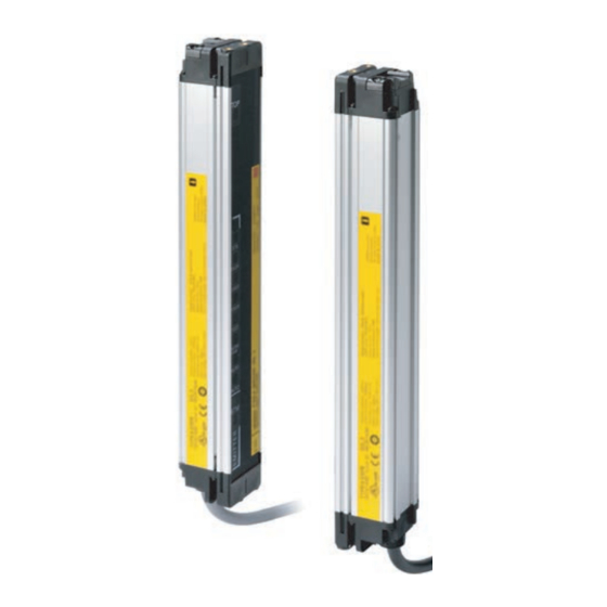
2. System Components Receiver Emitter Beam center-line mark Beam 1. Top-beam-state indicator (Blue) 1. Top-beam-state indicator (Blue) Indicator Receiver 2. Stable-state indicator (Green) 2. Stable-state indicator (Green) Emitter 3. ON/OFF-state indicator (Green/Red) 3. ON/OFF-state indicator (Green/Red) 4. Lockout indicator (Red) 4. -
Page 4: Wiring Examples
Pre-Operation Checklist / Function Selection Wiring Mounting/Beam Alignment Maintenance Checklists 5.Wiring Examples For wiring examples of input/output circuit and other wiring examples than below, refer to F3SJ-B-01T series user's manual. 5-1. Auto reset mode, external test used F39-JD…A-L F39-JD…A-D (Gray) Communication line (+) (Pink) Communication line (-) +24 VDC... -
Page 5: Mounting And Beam Alignment
Pre-Operation Checklist / Function Selection Wiring Mounting/Beam Alignment Maintenance Checklists 6. Mounting and Beam Alignment For brackets other than top/bottom brackets (F39-LJB1) and intermediate brackets (F39-LJB2) as well as external dimensions and mounting, refer to F3SJ-B-01T series user's manual. 6-1. Mutual Interference Prevention ■... -
Page 6: External Dimensions To Attach The Top/Bottom Brackets (F39-Ljb1) And Intermediate Brackets (F39-Ljb2)
Pre-Operation Checklist / Function Selection Wiring Mounting/Beam Alignment Maintenance Checklists 6-4. External dimensions to attach the top/bottom brackets (F39-LJB1) and intermediate brackets (F39-LJB2) ■ Dimensions (Check position) [Backside mounting] Step1 Check Top/Bottom Bracket dia.9 position (F39-LJB1) 2-M8 M3 x 6 screw 4-M5 Step2 Mount... - Page 7 Pre-Operation Checklist / Function Selection Wiring Mounting/Beam Alignment Maintenance Checklists ■ Dimensions (Check position) [Side mounting] Step1 dia.9 Top/Bottom Bracket Check (F39-LJB1) position 2-M8 M3 x 6 screw 4-M5 Step2 Mount Step3 Intermediate Bracket (F39-LJB2) Align beams 2-M5 2-M5 Top/Bottom Bracket (F39-LJB1) M3 x 6 screw <M5 screw fixed>...
-
Page 8: Mounting And Beam Alignment
Pre-Operation Checklist / Function Selection Wiring Mounting/Beam Alignment Maintenance Checklists 6-5. Mounting and Beam Alignment Mounting brackets are not included in the product. You must purchase them separately. Step1 1. Loosen the intermediate mounting bracket bolts. Check position <Backside mounting> Hexagon socket head cap screw (M3 x 12) Loosen... - Page 9 Pre-Operation Checklist / Function Selection Wiring Mounting/Beam Alignment Maintenance Checklists 3. Attach the top/bottom brackets to the case. <Backside mounting> Hexagon socket head cap screws (M3 x 6) Step1 (Recommended tightening torque: 0.54Nm) Tighten lightly Check Loosen position Anti-rotation hexagon socket head cap screw Tighten Step2...
- Page 10 Pre-Operation Checklist / Function Selection Wiring Mounting/Beam Alignment Maintenance Checklists 5. Align beams based on the indicators. Align the unit to the center of the angle where stable indicator (STB) turns ON Align the unit to the center Step1 of the angle where stable Emitter Receiver indicator (STB) turns ON...
-
Page 11: Pre-Operation Checklists / Maintenance Checklists
Pre-Operation Checklist / Function Selection Wiring Mounting/Beam Alignment Maintenance Checklists 7. Pre-Operation Checklists / Maintenance Checklists After wiring, mounting and beam alignment are done, check the operation of the F3SJ-B-01T. Pre-Operation Checklists After installation, the highest level administrator must use the following checklist to verify the operation, plac- ing a check mark in each of the boxes. - Page 12 Pre-Operation Checklist / Function Selection Wiring Mounting/Beam Alignment Maintenance Checklists □ The sensor can detect a test rod wherever it is in the detection zone. In other words, when a test rod is inserted into the detection zone, the stable-state indicators (STB) turn off and the ON/OFF output-state indicators turn red.
-
Page 13: Suitability For Use/Contact Information
Omron Companies shall not be responsible for conformity with any standards, codes or regulations which apply to the combination of the Product in the Buyer’s application or use of the Product. At Buyer’s request, Omron will provide applicable third party certification documents identifying ratings and limitations of use which apply to the Product. This information by itself is not sufficient for a complete determination of the suitability of the Product in combination with the end product, machine, system, or other application or use. - Page 14 □□□□ F3SJ-B N25-01T © OMRON Corporation 2017-2018 All Rights Reserved. Original instructions...
-
Page 15: 同梱物のご確認
本書は F3SJ-B-01T の配線から動作チ ェ ッ ク ま での流れを示 し た簡易説明書です。 詳細については F3SJ-B-01T の取扱説明書、 ユーザーズマニ ュ アルを当社ウ ェ ブサイ ト か ら ダウン ロー ド し 、 よ く お読み く だ さ い。 http://www.fa.omron.co.jp 目次 1. 同梱物のご確認....................................1 2. 各部の名称......................................2 3. -
Page 16: 各部の名称
2. 各部の名称 3. ラ イ ト カ ーテ ン セ ッ ト ア ッ プの流れ ..2 ページ ..3 ページ ..4 ページ ..9 ページ 4. 機能選択フ ローチ ャ ー ト 使用する機能によ... -
Page 17: 配線例
5. 配線例 F3SJ-B-01Tシ リ ーズユーザーズマニ ュ アル 入出力回路および下記以外の配線例については、 を参照し て く だ さ い。 5-1. オー ト リ セ ッ ト モー ド 、 外部テ ス ト 使用 *1 微小負荷用ス イ ッ チ(入力仕様 : 24V、 1.0mA以下)を ご使用 く だ さ い。 *2 K1が未接続で... -
Page 18: 取 り 付け ・ 光軸調整
6. 取 り 付け ・ 光軸調整 F3SJ-B-01Tシ リ ーズユー 上下金具(形F39-LJB1)、 中間金具(形F39-LJB2)以外の金具、 外形寸法および取 り付け方法については、 ザーズマニ ュ アル を参照し て く だ さ い。 6-1. 上下金具 ( 形 F39-LJB1)、 中間金具 ( 形 F39-LJB2) を取 り 付ける場合の外形寸法 ■外形寸法図 (取 り 付け位置確認) [ 背面取 り 付け時 ] [ 単位... - Page 19 ■外形寸法図 (取 り 付け位置確認) [ 側面取 り 付け時 ] [ 単位 : mm ] 寸法A~Eについて 寸法A C+69 寸法B C+42.2 寸法C 形式中の4桁の数字 (検出幅) 寸法D C-45 寸法E 検出幅によ っ て変わ り ます。 下表を確認 く だ さ い。 寸法Eについて 検出幅 中間金具の数 寸法E 0185~1105 1185~1345 C/2以下...
-
Page 20: 取 り 付け方法 と 光軸調整
6-2. 取 り 付け方法 と 光軸調整 取付金具は本体に付属 し ていません。 別途購入いただ く 必要があ り ます。 1. 中間金具のボル ト を緩めます。 2. 中間金具を ケースに仮締め し ます。 中間金具取 り 付け位置、 個数については、 本紙6-1項参照 く だ さ い。 F3SJ-B-01T ク イ ッ ク イ ンス ト ールマニ ュ アル... - Page 21 3. 上下金具を ケースに取 り 付けます。 4. 壁面へ固定 し ます。 壁面 と の取 り 付けネジは付属 し ていません。 F3SJ-B-01T ク イ ッ ク イ ンス ト ールマニ ュ アル...
- Page 22 5. 表示灯を参考に光軸調整を行います。 RECEIVER EMITTER 中間取付金具(形F39-LJB2)の角度調整範囲は±30°です。 6. 仮締め し ていた上下金具、 中間金具の回転止め六角穴付ボル ト (M3 × 8、 M3 × 18) を本締め し ます。 各ネジは1 ヶ 所ずつ締めるのではな く 、 全箇所バラ ン ス よ く 本締め し て く だ さ い。 推奨値を大き く 超え る ト ル ク で固定する と 故障の原因 と な り ます。 F3SJ-B-01T ク...
-
Page 23: 動作チ ェ ッ ク
オムロン 0120-919-066 携帯電話 ・ PHS ・ IP電話な ど ではご利用いただけませんので、 下記の電話番号へおかけ く だ さ い。 055-982-5015 電話 (通話料がかかり ます) ■営業時間:8:00〜21:00 ■営業日:365日 ●FAXやWebページでもお問い合わせいただけます。 055-982-5051 www.fa.omron.co.jp FAX ●その他のお問い合わせ 納期・価格・サンプル・仕様書は貴社のお取引先、または貴社担当オムロン販売員にご相談ください。 オムロン制御機器販売店やオムロン販売拠点は、Webページでご案内しています。 F3SJ-B-01T ク イ ッ ク イ ンス ト ールマニ ュ アル...
Need help?
Do you have a question about the Sti F3SJ-B N25-01T Series and is the answer not in the manual?
Questions and answers