
Related Manuals for Omron F3SN-B P Series


Summary of Contents for Omron F3SN-B P Series
- Page 1 F3SN-B Series セーフティライトカーテン Safety Light Curtain 取扱説明書 Instruction Manual A TYPE 2 日本語 PNP Output Type B ENGLISH Cat.No.SCEE-717...
- Page 2 はじめに このたびは、セーフティライトカーテン形F3SN-Bシリーズ(以下F3SN-Bと呼びます)をお買い上げいただ き、ありがとうございます。 本書はF3SN-Bの使用方法について説明しています。 ご使用に際して、次のことを守ってください。 F3SN-Bは、設置される機械について十分に理解した担当者が取扱ってください。 • F3SN-Bは、設置環境、機械の性能・機能に対応して正しく使われることが前提となっています。関係 • 者によるリスクアセスメントを実施したうえでの設置をお願いします。 ご使用の前に本書をよく読んで十分にご理解の上、正しくご使用ください。 • この取扱説明書は、いつでも参照できるよう、大切に保管してください。 • 法規・規格について センサ単体では、労働安全衛生法第四十四条の二による「型式検定」には申請できず、システムでの申 請が必要となります。したがって、F3SN-Bを日本国内で同法第四十二条で定められた「プレス機械又は シャーの安全装置」としては使用する場合には、システムで検定を受けていただく必要があります。 2. (1) F3SN-Bは、EU(欧州連合)機械指令附属書IV B.安全部品 第1項で指定される電気感知式保護装置 (ESPE:Electro-Sensitive Protective Equipment)です。 (2)F3SN-Bは、以下の海外法規、規格に適合しています。 ①EU法規 - 機械指令 Directive 98/37/EC - EMC指令 Directive 89/336/EEC EN61496-1(タイプ2 ESPE)、prEN61496-2(タイプ2 AOPD) ②欧州規格 IEC61496-1(タイプ2 ESPE)、IEC61496-2(タイプ2 AOPD)...
- Page 3 ご使用に際してのお願い 次に示すような条件や環境でご使用の場合は、 定格、 機能に対して余裕を持った使い方やシステムとしての安 全対策へのご配慮をいただくようお願いいたします。 (1)本書に記載のない条件や環境での使用 (2)特に安全性が要求される装置、設備への使用(原子力制御・鉄道・航空・車両・燃焼設備・医療システ ム・宇宙開発・大型娯楽機械など) 安全上のご注意 安全にご使用いただくための表示と意味について 本書では、F3SN-Bを安全にご使用いただくために、注意事項を次のような表示で示しています。ここで 示した注意事項は、安全に関する重大な内容を記載しています。必ず守ってください。表示と意味は次の とおりです。 警告 誤った取り扱いをすると、人が死亡または重傷を負う可能性が想定される場合を示します。 一般的禁止を示します。 警告 電気的制御による急停止が可能でない機械には適用できません。例えば、フル回転クラッチを用いた機械プレスには使 用しないでください。機械の危険部に到達する前に機械が止まらず、重傷を負う恐れがあります。(2-1章) 検出領域を通過してのみ機械の危険部に到達できるように機械周辺に防護構造物を設置してください。 機械の危険部で作業を行うとき、常に人体の一部が検出領域内に残るように設置してください。 人体が検出されず、重傷を負う恐れがあります。(2-1章) インターロックリセットスイッチは、危険領域全体が見え、かつ危険領域内から操作できない位置に設置してください。 (2-1章) F3SN-Bを引火性、爆発性ガスの雰囲気中で使用しないでください。爆発の恐れがあります。(2-1章) F3SN-Bは、危険領域からの飛来物に対して人体を防護することはできません。別途覆いまたは囲いを設けてください。 (2-1章) F3SN-Bと危険部の間には、必ず安全距離を確保してください。機械の危険部に到達する前に機械が止まらず、重傷を負 う恐れがあります。(2-1章) 光沢面からの影響を受けないように設置してください。検出不能状態となり、重傷を負う恐れがあります。(2-1章) 対向する投光器と受光器は同じセット形式のものをご使用ください。誤った組合せでご使用になると検知不能領域が生 じます。(2-1章) 本体の取りつけ、コードコネクタは確実に締めてください。(2-1章) 複数セットのF3SN-Bを使用するときは、しゃ光板を使用するなどして、相互干渉が発生しないように設置してください (2-1章)。 負荷は出力と0Vラインの間に接続してください(PNP出力)。誤って出力と+24Vラインの間に接続すると、動作モー ドが「しゃ光時ON」に反転して危険です(2-4章)。 出力線を+24Vラインに短絡させないでください。出力が常時ONとなり危険です。 また、出力線の地絡によって出力がONとならないよう、電源の0V側を接地してください。(2-4章) 制御出力は必ず2系統とも使用して安全システムを構成してください。1系統だけで安全システムを構成した場合、出力 回路の故障時に重傷を負う恐れがあります。(2-4章) F3SN-Bの各ラインをDC24V+10%以上のDC電源に接続しないでください。また、AC電源にも接続しないでください。...
- Page 4 警告 F3SN-BがIEC 61496-1およびUL 508を満たすために、DC電源ユニットは下記の項目すべてを満たすようにしてくださ い。(2-4章) • 定格の電源電圧内(DC24V±10%)である • F3SN-Bおよびセーフティコントローラ、 ミューティングセンサなどのF3SN-Bの電気感知式保護機能に関わる装置 専用とし、他の装置・機器には接続しない。また、複数の装置に接続する場合には、各装置の総定格電流に対して 余裕を持たせる。 • EMC指令適合(工業環境) • 一次回路・二次回路間が二重絶縁あるいは強化絶縁 • 過電流保護特性が自動復帰(逆L垂下形) • 出力保持時間が20 ms以上 • UL508で定義されるクラス2回路または制限電圧電流回路の出力特性要求を満たす。(2-4-1 注釈参照) • 本ユニットが使用される国、地域でのEMCと電気機器安全に関する法規・規格に従う電源である。 (例:EUではEMC指令、低電圧指令に適合の電源であること。) 市販のスイッチングレギュレータを使用する場合、FG(フレームグランド端子)を接地してください。接地されません とスイッチングノイズで誤動作することがあります。 F3SN-Bの設置、点検、メンテナンスに際しては、それらが正しく実行されたことを責任者が必ず確認してください。 本体を分解、修理、改造しないでください。本来の安全機能が失われ危険です。 反射形の構成では使用しないでください。検出不能状態になることがあります。ミラーによる光のルートの変更は問題 ありません。(2-1章) 反射板 A-iii...
- Page 5 お願い 次に示す項目は安全を確保するために必ず守ってください。 (1)本書をよく読んで、設置手順、動作確認手順、及びメンテナンス手順を十分にご理解の上、ご使用くだ さい。 (2)負荷は、下記の項目すべてを満たすようにしてください。 短絡させない • 定格以上の電流を流さない • (3)感電保護のために F3SN-B の全ての入出力線は危険電圧(AC230V など)から二重絶縁あるいは強化絶 縁により絶縁してください。 また形 F3SP-B1P との組み合わせて使用する場合、 全てのリレー接点(13-14、 23-24、33-34、41-42)は危険電圧から基礎絶縁により絶縁してください。 (4)廃棄するときは、産業廃棄物として処理してください。 正しい使い方 製品の破損、劣化や、誤動作を避けるため、以下の項目を守ってださい。 設置環境について 次のような場所には設置しないでください。 • - 直射日光など、強い外乱光があたる場所 - 湿度が高く、結露する恐れがある場所 - 腐食性ガスがある場所 - 仕様で定められる以上の振動や衝撃が、本体に伝わる場所 - 水がかかる場所 F3SN-Bの間近で携帯電話やトランシーバを使用しないでください。 • 配線・取りつけについて 配線は、必ず電源OFFの状態で行ってください。故障診断機能により、センサが動作しなくなること • があります。...
- Page 6 ご使用の前に 箱の中に次の部品が揃っていることを確認してください。 梱包には万全を期しておりますが、 万一不足があり ましたら、お近くの当社支店・営業所までお問合わせください。 形F3SN-B□□□□P□□本体×1セット(投光器×1、受光器×1) • 取付金具(上・下)×4セット • M4×8ネジ 上下金具 取付金具(中間) • 取り付け間隔が640mm以上のセンサに付属しています。 センサ全長により、 640mm以内で固定できる 数量(投・受光器各々MAX. 2セット)が付属しています。 M5×8ネジ 中間金具(3) 中間金具(2) M4×6ネジ 中間金具(1) ライトカーテンに挿入済み テストロッド×1本 • 形F3SN-B□□□□P25シリーズ用・・・直径25mm 形F3SN-B□□□□P40シリーズ用・・・直径40mm (形F3SN-B□□□□P70シリーズには付属しません。) エラーモードラベル ×1枚 • 取扱説明書(本書)×1冊 •...
-
Page 7: Table Of Contents
目 次 1章 概要 ................................1 1-1 特長 ................................1 1-2 機能説明 ..............................1 1-2-1 インターロック機能 .........................1 1-2-2 テスト機能 ............................2 1-2-3 補助出力............................2 1-2-4 外部リレーモニタ機能........................3 1-2-5 検出領域............................3 1-2-6 表示灯 ...............................4 1-3 定格/性能 ..............................5 1-3-1 定格/性能表 ............................5 1-3-2 応答時間............................6 2章 配線と取りつけ ............................7 2-1 設置条件 ..............................7 2-1-1 検出領域と侵入経路... -
Page 8: 1章 概要
1章 概要 1章 概要 1-1 特 長 検出距離:10m 最小検出物体 形F3SN-B□□□□P25シリーズ:Φ25mm 形F3SN-B□□□□P40シリーズ:Φ40mm 形F3SN-B□□□□P70シリーズ:Φ70mm 検出幅(センサ長)が多様で装置に必要なサイズの選択が可能です。 形F3SN-B□□□□P25シリーズ:217mm~1822mm[15mm毎], 108仕様 形F3SN-B□□□□P40シリーズ:217mm~1807mm[30mm毎], 54仕様 形F3SN-B□□□□P70シリーズ:277mm~1777mm[60mm毎], 26仕様 上記のセンサには弊社工場におけるカスタマイズ対応品も含まれております。ご発注の際は、 [注]: 弊社営業担当にご相談ください。 センサ外形≒検出幅:一目でカバーしている領域が確認できます。 光量表示モニタ 5個のバーLEDで受光量を表示します。光軸あわせが簡単です。 エラーモードモニタ エラー発生時は、3個のバーLEDの表示状態でエラー内容を示します。 各種安全関連機能を装備 外部テスト(投光停止機能)、外部リレーモニタ機能、インターロック機能 補助出力を装備(ノンセーフティ出力) センサの各種状態をPLCに出力することが可能。 コントロールリレーユニット(形F3SP-B1P)を準備しました。(別売アクセサリ-) センサを使用した安全システム回路が容易に実現できます。 保護構造 IP65(センサのみ) 【形式基準】 ① 検出幅(mm) ① ② ③ ④ ②... -
Page 9: テスト機能
1章 概要 2)マニュアルリセット = スタート/リスタートインターロック 電源投入後、およびセンサをしゃ光した時にインターロック状態となります。 インターロック状態になるとセンサは制御出力をOFF状態のまま保持し、センサが入光状態となっても、 *1 制御出力はON状態となりません。検出領域にしゃ光物体がない状態で、リセット入力 を印加すること によりインターロック状態が解除され制御出力はON状態となります。 *1. リセット入力線に、9V~Vs(公称24V)の電圧を100ms以上印加後、オープンまたは0~1.5Vにします。 マニュアルリセット設定手順: ①インターロック選択入力線を9V~Vs(公称24V)と短絡する。 ②リセット入力線をリセットスイッチ(a接点)を介して、9V~Vs(公称24V)に接続する。 ③リセットスイッチ接点をオープンにしたまま、センサの電源を投入する。 インターロック状態を解除するためのスイッチは、危険領域の外で、かつ危険領域がよく見える [注1]: 位置に設置してください。 センサの非接続線は、他の配線との短絡防止を実施してください。 [注2]: 1-2-2 テスト機能 1)セルフテスト 電源投入時(1秒以下)にセルフテストを実施し異常の有無を確認します。また、動作中にも周期的にセ ルフテスト(1秒周期)を実施します。 2)外部テスト 任意のタイミングで投光を停止させ、出力が正常に ×4以下 ×2以下 OFFとなるか確認する機能です。 (注1) 投光器のテスト入力線に9V~Vsの電圧 を印加す テスト入力 L(オープン) ると投光が停止されます。 印加時間はT の4倍以上必要です。 [注1]: 制御出力... -
Page 10: 外部リレーモニタ機能
1章 概要 1-2-4 外部リレーモニタ機能 機械の危険部を制御する外部リレー(あるいはコンタクタ)の溶着などの動作不良を、そのb接点の動作を モニタすることにより検知する機能です。 受光器の外部リレーモニタ入力線に外部リレーのb接点を接続 *1 しモニタします。制御出力と外部リレーモニタ入力が正しい論理関係でなくなると、センサはただちに ロックアウト状態となり、制御出力をOFF状態とします。リレーの復帰時間により生じる遅れ時間に対し ては、300msまで異常なしと判断します。この機能を正しく使用するために、強制ガイド接点構造を持っ たセーフティリレーやコンタクタを使用してください。 [外部リレーモニタを使用しない場合] 外部リレーモニタを使用しない場合、しゃ光時ON動作設定となっている補助出力を外部リレーモニタ入 力に印加してください。 *1. 外部リレーモニタ入力線に、外部リレーのb接点を介して、9V~Vsの電圧が印加されるように配線します(2-4 参照) 1-2-5 検出領域 [検出幅] 検出幅=センサ全長 [光軸センターラインマーク] キャップの中央に並ぶ2本のラインが光軸中心を示します (下図参照) 。 このラインは安全距離を測定す るときの基準線に相当します。 常に2本ある線の危険領域側のラインを、安全距離の基準線としてくださ い。 光軸センターラインマーク 安全距離 検 出 幅 1 mm... -
Page 11: 表示灯
1章 概要 1-2-6 表示灯 【投光器】 Test Lockout Interlock Power ERROR LEVEL テスト表示灯(橙) ロックアウト表示灯(赤) インターロック表示灯(黄) 受光レベル表示灯(緑) エラーモード表示灯(赤) 電源表示灯(緑) 【受光器】 OFF出力表示灯(赤) エラーモード表示灯(赤) 受光レベル表示灯(緑) ON出力表示灯(緑) ロックアウト表示灯(赤) オプション機能表示灯(緑) Lockout ERROR LEVEL OPT 電源表示灯 :通電時・点灯 インターロック表示灯 :インターロック状態時・点灯 ロックアウト表示灯 :ロックアウト時・点滅 テスト表示灯 :外部テスト時・点灯、30000 時間経過時・点滅 ON出力表示灯 :制御出力ON時・点灯 OFF出力表示灯 :制御出力OFF時・点灯... -
Page 12: 定格/性能
1章 概要 1-3 定 格 /性 能 1-3-1 定格/性能表 形式中の□□□□には、検出幅(mm)が4桁の数字で入ります。 形式 形F3SN-B□□□□P25 形F3SN-B□□□□P40 形F3SN-B□□□□P70 項目 不透明体 不透明体 不透明体 最小検出物体 直径 25mm 直径 40mm 直径 70mm 15 mm 30mm 60mm 光軸ピッチ(P) 13~120 7~60 5~30 光軸数(n) 217 ~ 1822 mm 217 ~ 1807 mm 277 ~... -
Page 13: 応答時間
1章 概要 形式 形F3SN-B□□□□P25 形F3SN-B□□□□P40 形F3SN-B□□□□P70 項目 周囲温度 動作時:-10~55℃(ただし氷結しないこと)、 保存時:-30~70℃ 周囲湿度 動作時:35~95%RH(ただし結露しないこと)、 保存時:35~95%RH 白熱ランプ:受光面照度3,000 Ix以下、 太陽光:受光面照度10,000 Ix以下 使用周囲照度 20MΩ以上(DC500 Vメガにて) 絶縁抵抗 耐電圧 AC1,000V、50/60Hz、1min 保護構造 IP65(IEC60529) 耐振動 誤動作 :10~55Hz、 複振幅0.7mm、 X、Y、Z各方向 20掃引 耐衝撃 誤動作 :100m/s 、 X、Y、Z各方向 1000回 × 4P)、編組シールド付き、許容曲げ半径R36mm 延長コード (別売) *3 UL20276(難燃性)、8芯(0.3mm ケース... -
Page 14: 2章 配線と取りつけ
2章 配線と取りつけ 2章 配線と取りつけ 2-1 設 置 条 件 2-1-1 検出領域と侵入経路 警告 電気的制御による急停止が可能でない機械には適用できません。例えばフル回転クラッチを用いた機械プレスには 使用しないでください。機械の危険部に到達する前に機械が止まらず重傷を負う恐れがあります。 検出領域を通過してのみ機械の危険部に到達できるように機械周辺に防護構造物を設置してください。 機械の危険部で作業を行うとき、常に人体の一部が検出領域内に残るように設置してください。 人体が検出されず、重傷を負う恐れがあります。 インターロックリセットスイッチは、危険領域全体が見え、かつ危険領域内から操作できない位置に設置してくだ さい。 F3SN-Bを引火性、爆発性ガスの雰囲気中で使用しないでください。爆発する恐れがあります。 F3SN-Bは、 危険領域からの飛来物に対して人体を防護することはできません。 別途覆いまたは囲いを設けてください。 本体の取りつけ、コードコネクタは確実に締めてください。 正しい設置 作業中に人体がセンサの検出領 センサの検出領域を通過しての 域内にある み機械の危険部に到達できる 誤った設置 人体がセンサの検出領域と機械 センサの検出領域を避けて機械 の危険部の間にある の危険部に到達できる... -
Page 15: 安全距離
2章 配線と取りつけ 2-1-2 安全距離 警告 F3SN-Bと危険部の間に安全距離(S)を確保してください。 機械の危険部に到達する前に機械が止まらず、重傷を負う恐れがあります。 安全距離とは、 人体や物体が機械の危険部に到達する前に危険部を停止させるため、 F3SN-Bと危険部が最 低限離されなければならない距離のことです。人体がセンサの検出領域に対して垂直に侵入する場合、安 全距離は次に示す考え方によって計算されます。 安全距離(S)=検出領域への侵入速度(K)×機械とセンサの合計応答時間(T) +センサの最小検出物体直径から計算される追加距離(C) ・・・(1)式 安全距離は各国の規格や機械の個別規格によって異なります。 安全距離 また侵入方向がセンサの検出領域に対して垂直ではない場合は計 光軸センター 算式が異なります。必ず関連規格を参照してください。 ラインマーク 危険部 <参考> 欧州規格EN999で規定される安全距離の計算法 (検出領域へ垂直に侵入する場合) 【最小検出物体直径が40mm以下のシステム】 本文中の(1)式に対し、K=2,000mm/s、C=8(d-14mm)として 侵入方向 次のように計算します。 S=2,000mm/s×(Tm+Ts)+8(d-14mm) ・・・(2)式 検出領域 ここで S=安全距離(mm) Tm=機械の応答時間 (s) *1 Ts=センサの応答時間 (s) *2 d=センサの最小検出物体直径... - Page 16 2章 配線と取りつけ <参考> 米国規格ANSI/RIA R15.06で規定される安全距離の計算法(検出領域へ垂直に侵入する場合) 安全距離 Ds = K×(Ts+Tc+Tr)+ Dpf (4式) K=侵入速度:1,600 mm/秒以上 ここで Ts=機械/設備の最大停止時間(秒) Tc=制御システムの最大停止時間(秒) Tr=センサの応答時間(秒)*1 Dpf=追加距離 (mm) 最下部の光軸高さが床面より300mm、最上部の光軸高さが床面より1200mmの位 置になるように設置した場合、Dpf=900 mm となります。 {計算例} 検出領域に対して垂直に侵入、K=1600mm/秒、Ts+Tc=0.06秒、Tr=0.01秒、Dpf=900mm: S= 1600×(0.06+0.01)+900 = 1012 mm センサの応答時間は、ON→OFFへの応答時間です。...
-
Page 17: 光沢面からの距離
2章 配線と取りつけ 2-1-3 光沢面からの距離 警告 光沢面からの反射の影響を受けないように設置してください。検出不能状態となり、重傷を負う恐れがあります。 金属製の壁や床、天井、ワークなどの光沢面(反射率の高い面)から以下に示す距離D以上離して設置し てください。 光沢のある天井 光沢面 投光器 投光器 受光器 受光器 10° 10° 検出領域 光沢のある床面 投光器と受光器の距離 設置許容距離D (検出距離L) 0.27m 0.2~3mのとき L/2 × tan10°= L × 0.087 (m) 3m以上のとき 2-1-4 相互干渉の防止方法 警告 対向する投光器と受光器は同じセット形式のものをご使用ください。誤った組合せでご使用になると検知不能領域 が生じます。 反射形の構成では使用しないでください。検出不能状態になることがあります。ミラーによる光のルートの変更は 問題ありません。 複数セットのF3SN-Bを使用するときは、しゃ光板を使用するなどして、相互干渉が発生しないように設置してくだ さい。 配線等の事情により、2セット以上のセンサを使用する場合、相互干渉が発生しないように配置してくだ... - Page 18 2章 配線と取りつけ 【相互干渉が発生しない設置形態】 ・2セット間で投光方向が異なるようにする(千鳥配置) <正> <正> 受光器1 投光器1 受光器1 投光器2 受光器2 投光器1 受光器2 投光器2 <正> 受光器1 投光器1 受光器2 投光器2 ・2セット間にしゃ光板を設置する <正> 投光器1 受光器1 投光器2 受光器2 ・干渉しない距離まで離して設置する <正> 投光器 受光器 <正> 投光器と受光器の 距離 設置許容距離D 投光器 受光器 (検出距離L) 10° 0.54m 0.2~3mのとき 投光器 受光器...
-
Page 19: 外形寸法図
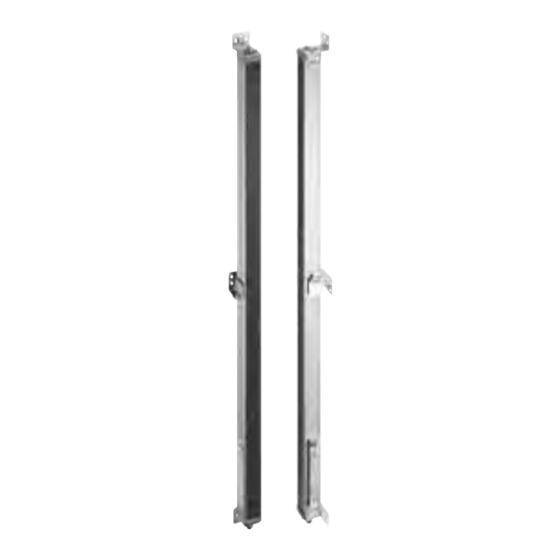
2章 配線と取りつけ 2-2 外 形 寸 法 図 2-2-1 側面取りつけ時(代表例:投光器の場合) 形F3SN-B□□□□P□□ 検出幅(C1) 中間金具使用数 寸法F(注) 寸法C1(検出幅):形式中の4桁の数字 寸法A = C1+64 ~0640 - 寸法B = C1+32 0641~1280 F=B/2 寸法E = C1-37 1281~1822 F=B/3 寸法F:右表参照 上記計算により得られた値Fを使 [注]: 用しない場合は、F=670mm以下としてください。 取付穴加工寸法 2-取付金具 4-M5 φ6.5 2-取付穴 2-M5 2-M5 2-取付穴... -
Page 20: 背面取りつけ時(代表例:投光器の場合
2章 配線と取りつけ 2-2-2 背面取りつけ時(代表例:投光器の場合) 形F3SN-B□□□□P□□ 寸法C1(検出幅):形式中の4桁の数字 検出幅(C1) 中間金具使用数 寸法F(注) 寸法A = C1+64 ~0640 - 寸法B = C1+32 0641~1280 F=B/2 寸法E = C1-37 1281~1822 F=B/3 寸法F:右表参照 上記計算により得られた値Fを使 [注]: 用しない場合は、F=670mm以下としてください。 取付穴加工寸法 2-取付金具 4-M5 φ6.5 2-取付穴 2-M5 2-M5 2-取付穴 中間金具 M5十字穴付 アプセット六角ボルト 光軸... -
Page 21: 取りつけ
2章 配線と取りつけ 2-3 取 り つ け 2-3-1 取りつけ方法 F3SN-Bのコード曲げ半径がR36(mm)以上となるようにしてください。コードの経年劣化により、機 能不良が生じることがあります。 52mm以上 コネクタコード コネクタコード 投光器・受光器の取付金具がとりついた状態を示します。中間金具の組み付け方法及び、取付穴加工位 置が対称になります。 取付穴 取付穴 投光器 受光器 A-14... -
Page 22: 取りつけ金具外形図
2章 配線と取りつけ 2-3-2 取りつけ金具外形図 取りつけ金具(上・下) φ6.50 φ9.00 φ14.2 φ22 8-R2.15 R2以下 材質:鉄 取りつけ金具(中間) 背面取りつけ時の形状 金具固定ネジ(M5×8) φ6.5 中間金具(3) φ9 中間金具(2) センサ取付ネジ(M4×6) 材質:鉄 側面取付時の形状 A-15... - Page 23 2章 配線と取りつけ 付属の取付金具を使用する場合の取付手順 ① 下面金具(電源コネクタ側)を壁面、柱等に固 ① ② ③ 定します。 ② 中間金具(3)を壁面、柱等に固定します。 [注]: 投受光器でアームが上下逆になります。 ③ 中間金具(2)をセンサ背面の中間金具(1)の突 起に合わせ、付属ネジ(M4×6)で仮締めし ます。 ④ ⑤-1 ⑤-2 中間金具(3)と方向が合うよう取り付け [注]: てください。 ④ センサの電源コネクタ部を下面金具に挿入し ます。 ⑤ 中間金具(2)を中間金具(3)と高さの合う位置 まで移動させ(⑤-1)、M4×6ネジを本締 めします(⑤-2)。 [注]: 必ず上面金具(キャップ側)を取り付け ⑥-1 ⑥-2 ⑥-3 る前に行ってください。 ⑥ 中間金具(2)と中間金具(3)をセンサの取付方 向に合わせた後、付属ネジ(M5×8)で仮締 めします。取付状態は、⑥-1,⑥-2,⑥- 3のような3種類ができます。...
-
Page 24: 電源ユニットについて
2章 配線と取りつけ 2-4 配 線 警告 出力線を+24Vラインに短絡させないでください。出力が常時ONとなり危険です。 また、出力線の地絡によって出力がONとならないよう、電源の0V側を接地してください。 負荷は出力と0Vラインの間に接続してください。(PNP出力) 誤って出力と+24Vラインの間に接続すると、動作モードが「しゃ光時ON」に反転して危険です。 制御出力は必ず2系統とも使用して安全システムを構成してください。1系統だけで安全システムを構成した場合、 出力回路の故障時に重傷を負う恐れがあります。 F3SN-Bの各ラインをDC24V+10%以上のDC電源に接続しないでください。また、AC電源にも接続しないでくだ さい。感電の可能性があり危険です。 (正) (誤) 茶 茶 +24 V +24 V 緑、白 F3SN-B F3SN-B 負荷 受光器 受光器 負荷 緑、白 青 青 2-4-1 電源ユニットについて 警告 F3SN-BがIEC 61496-1およびUL 508を満たすために、DC電源ユニットは下記の項目すべてを満たすようにしてく ださい。 • 定格の電源電圧内(DC24V±10%)である... -
Page 25: 配線図
2章 配線と取りつけ 2-4-2 配線図 センサ単体使用時 ・マニュアルリセット、外部リレーモニタ機能使用時の配線 投光器 受光器 投光器用コード 受光器用コード F39-JC□A-L F39-JC□A-D RS-485(A) (灰) RS-485(B) (桃) (注1) (注1) +DC24V 電源 S1:外部テストスイッチ S2:インターロック/ロックアウトリセットスイッチ K1,K2:機械の危険部を制御するリレー等 注1)微少負荷用スイッチを K3:負荷、PLC等(モニター用) ご使用下さい。 ・オートリセット時の配線 投光器 ・外部リレーモニタ不使用時 受光器 (注1) (注1) S3:ロックアウトリセットスイッチ (スイッチが不要な場合、DC24Vに接続) 注2)K3が不要な場合、補助 (注2) 出力は外部リレーモニタ 入力と接続するのみでよ い。 A-18... - Page 26 2章 配線と取りつけ 形F3SP-B1Pとの組み合わせ時 ・マニュアルリセット、外部リレーモニタ機能使用時の配線 投光器 受光器 投光器用コード 受光器用コード F39-JC□B-L F39-JC□B-D S1 (注1) (注1) インターロック リセット テスト 選択 制御出力1 制御出力2 外部リレー 補助 モニタ 出力 F3SP-B1P +DC24V (注2) 電源 S1:外部テストスイッチ S2:インターロック/ロックアウトリセットスイッチ ・オートリセット時の配線 KM1,KM2:機械の危険部を制御するリレー等 K3:負荷、PLC等(モニター用) 注1) 微少負荷用スイッチをご使用下さい。 S1 2) 外部リレーモニタを使用しない場合、T31とT32を短 絡して使用してください。 (注1) (注1) インターロック...
-
Page 27: 配線方法
2章 配線と取りつけ 2-4-3 配線方法 1. 投光器に投光器用コード(別売り:F39-JC□□-L、色:灰)を接続してください。 2. 受光器に受光器用コード(別売り:F39-JC□□-D、色:黒)を接続してください。 3. 電源の 0 Vラインを保護アース(PE)と直接接続してください。 正しく配線してください。F3SN-Bが破損する恐れがあります。コードの色、及びコネクタの樹 [注]: 脂部の色(投光器:灰色・受光器:黒色)を確認してください。色を合わせることで配線ミスが 防止できます。 コネクタ(本体側) 信号名 延長コード ピン 正面図 の線色 受光器 投光器 インターロック選択入力 制御出力2(OSSD2) 白 (INTERLOCK) +24 V(24VDC) +24 V(24VDC) 茶 テスト入力 (TEST) 制御出力1(OSSD1) 緑 補助出力 (AUXILIARY) リセット入力(RESET) 黄... - Page 28 2章 配線と取りつけ 両側コネクタコード:形F3SP-B1Pとの接続および、延長用コード(別売:F39-JC□B) 40.7 44.7 ボディ色:黒 ボディ色:黒 M12防水コネクタ M12防水コネクタ ビニル絶縁丸形コード Φ6.6 8芯(4対) (導体断面積:0.3mm / 絶縁体径:Φ1.15mm) 単位: mm セット形式 投光器用 受光器用 F39-JCR2B F39-JCR2B-L 灰色コード F39-JCR2B-D 黒色コード F39-JC1B F39-JC1B-L F39-JC1B-D 1000 F39-JC3B F39-JC3B-L F39-JC3B-D 3000 F39-JC7B F39-JC7B-L F39-JC7B-D 7000 F39-JC10B F39-JC10B-L F39-JC10B-D 10000 F39-JC15B F39-JC15B-L...
-
Page 29: 調整方法
2章 配線と取りつけ 2-4-4 調整方法 [手順] 1.以下のことを確認してください。 投光器と受光器の光学面が汚れていないこと。 • F3SN-Bの検出領域にしゃ光物体がないこと。 • 2.投光器の光軸を調整する。 受光レベル表示灯を見ながら投光器のねじれ角を調整して、受光レベル表示灯が点灯する角度の中心に 投光器を合わせる。 3.受光器を調整する。 受光レベル表示灯を見ながら受光器のねじれ角を調整して、受光レベル表示灯が点灯する角度の中心に 受光器を合わせる。 4.受光レベル表示灯が5ヶ全て点灯していることを確認してください 5.以上の調整が完了したら、センサの光軸調整状態が変わらないように注意し、すべての金具固定ねじと 取りつけねじを本締めしてください。付属のねじに対する締めつけトルクを以下に示します。 ねじの呼び×長さ 締めつけトルク 取りつけ金具種類 (mm) M4×8 1.2N・m 取りつけ金具 (上・下) M4×6 1.2N・m 取りつけ金具 (中間) M5×8 2.0N・m 6.受光器の角度調整をおこなっても5ヶ全ての受光レベル表示灯が点灯しない場合、投光器の取りつけ面 と受光器の取りつけ面の平行度と、投光器と受光器の取りつけ高さに問題がないか確認してください。 2-5 チ ェ ッ ク リ ス ト 最終責任者がチェックリストに従って□にチェックしてください。... - Page 30 2章 配線と取りつけ 機械が停止している状態で、下記の通り正しく動作するか確認してください。 1.□テストロッド 注1 が変形していないこと。 2.□検出領域に何もない状態とします。 F3SN-Bの電源投入後、1秒以内に電源表示灯、及び受光レベル表示灯が全点灯すること。 3.□テストロッドが、 検出領域内のどの位置にあっても検出できる。 つまり、 テストロッドを検出領域内に侵入させると、受光レベル表示灯が5ヶす べて消灯し、OFF出力表示灯が点灯すること。 検出確認は図のようにテストロッドを移動させて行なってください。 [注1] 形F3SN-B□□□□P70には、テストロッドが付属していません。 4.□外部テスト機能を使用する時: テスト入力ラインを9~24Vに短絡すると、OFF出力表示灯が点灯する。 5.□外部リレーモニタ機能を使用する時: センサをしゃ光し、外部リレーモニタ入力端子をオープンにすると、ロ ックアウト状態となる。 6.□スタート/リスタートインターロック機能を使用する時: センサの電源を投入後、センサを入光状態としても、OFF出力表示灯は点灯したままである。 リセットSWを入力するとON出力表示灯が点灯する。 ON出力表示灯が点灯している状態で、センサをしゃ光し、続けて入光状態に戻しても、OFF出力 表示灯は点灯したままである。リセットSWを入力するとON出力表示灯が点灯する。 機械が動作する状態にし、危険部の停止を以下のように確認してください。 1.□「投光器直前」「受光器直前」「投光器と受光器の中間」の3ヶ所でテストロッドを検出領域内に侵入 させると、危険部はすぐに停止すること。(前記3.に示したように正しいテストロッドを使用してく ださい) 2.□テストロッドが検出領域内にある限り、危険部は停止を続けること。 3.□F3SN-Bの電源をしゃ断すると、危険部が停止すること。 4.□機械全体の応答時間実測値が計算値以下であること。 A-23...
-
Page 31: 3章 入出力回路
3章 入出力回路 3章 入出力回路 表示部 茶 +24V 緑 テスト入力(*1) 投光器 白 主回路 インターロック選択入力(*2) 黄 リセット入力(*2) 青 灰 桃 RS-485(A) RS-485(B) 灰 桃 茶 赤 外部リレーモニタ入力(*2) 受光器 緑 主回路2 制御出力1 負荷 白 制御出力2 受光器 主回路1 負荷 黄 補助出力 負荷 表示部 青 *1. - Page 32 3章 入出力回路 制御出力の出力波形 センサが入光状態にあるとき、出力回路をテストするために、下図のように制御出力は周期的にOFFされ ます。このOFF信号がフィードバックされると、出力回路は正常と診断されます。出力信号にOFFパルス 信号が含まれない場合、受光器は出力回路あるいは配線の異常と診断し、ロックアウト状態になります。 応答時間(ON→OFF) 制御出力1、2 OFF信号 約25μs 160~200μs また、同様にセンサがしゃ光状態にあるときも、出力回路のテストを行います。 センサに接続される機器が、 このOFFパルス信号/ONパルス信号によって誤動作しないよう、 機器の入力 応答時間にご注意ください。 応答時間(ON→OFF) 制御出力1、2 ON信号 約130μs A-25...
-
Page 33: 4章 アプリケーション
4章 アプリケーション 4章 アプリケーション F3SN-Bを使用したモータ制御システムの例を示します。 本システムのEN954-1によるカテゴリ-は2です。 アプリケーション1 投光器 受光器 - 形F3SP-B1Pとの組み合わせて使用 - マニュアルリセットモード - 外部リレーモニタ機能を使用 入光 しゃ光 外部テストスイッチ(S1) リセットスイッチ(S2) 制御出力 K1, K2 a接点 インターロック KM1, KM2 a接点 テスト リセット 補助出力 選択 OSSD1 OSSD2 K1, K2 b接点 KM1, KM2 b接点 外部リレー 補助出力の出力動作モードに... - Page 34 4章 アプリケーション アプリケーション3 - セーフティリレーユニット形G9SA-301と組み合わせて使用 - センサの設定 ・オートリセットモード 投光器 受光器 ・外部リレーモニタ機能無効(配線により) - セーフティリレーユニットの設定 ・マニュアルリセットモード ・フィードバックループを使用 - 非常停止スイッチを使用 RS-485(A) (灰) 入光 RS-485(B) (桃) しゃ光 外部テストスイッチ (S1) リセットスイッチ (S2) 非常停止スイッチ (S3) 制御出力 K1, K2 a接点 KM1, KM2 a接点 +DC24V K1, K2 b接点 KM1, KM2 b接点...
-
Page 35: 5章 メンテナンス
5章 メンテナンス 5章 メンテナンス 警告 必ず、以下の点検が正常に終了してから、 F3SN-B を使用してください。けがや死亡につながることがあります。 本体を分解、修理、改造しないでください。本来の安全機能が失われ危険です。 [お願い] 安全の確保のため、点検結果を記録し保管してください。 F3SN-Bと機械について十分理解した上で、点検をおこなってください。 設置者、設計技術者と使用者が異なる場合は、使用者にメンテナンスに関する指導を十分におこなってく ださい。 5-1 日 常 の 点 検 始業時、作業者交代時には、次の点検項目を確認してください。 1.□F3SN-Bの検出領域以外に機械の危険部への侵入経路がないこと。 2.□機械の危険部で作業を行うとき、体の一部がF3SN-Bの検出領域内に残ること。 3.□安全距離の実測値が計算値以上であること。 4.□F3SN-Bの光学面やスパッタ保護カバ-(形F39-HN、別売)に汚れや傷がないこと。 5.□テストロッドが変形していないこと。 6.□検出領域に何もない状態とし、F3SN-Bの電源を投入します。 オートリセットモード時: 電源投入後、1秒以内に電源表示灯とON出力表示灯が 点灯すること。 マニュアルリセットモード時: 電源投入後、1秒以内に電源表示灯とOFF出力表示灯が 点灯すること。 7.□右図のように検出領域内でテストロッドを移動させたときに、 テストロッドが検出できること。つまり、テストロッドを検出 領域内に侵入させると、受光レベル表示灯が5ヶすべて消灯し、 OFF出力表示灯が点灯すること。 機械が動作する状態にし、危険部の停止を以下のように確認してください。 8.□検出領域に何も存在しない状態で、危険部が可動状態となっていること。 9.□「投光器直前」「受光器直前」「投光器と受光器の中間」の3ヶ所でテストロッドを検出領域内に 侵入させると危険部はすぐに停止すること(正しいテストロッドを使用してください)。... -
Page 36: 6章 トラブルシューティング
6章 トラブルシューティング 6章 トラブルシューティング 6-1 ロ ッ ク ア ウ ト 状 態 センサがロックアウトした場合、エラーモード表示灯が点滅しエラー内容を知らせます。 下表に従って対策を実施してください。 異常内容によっては、投光器または受光器のエラー表示灯しか点滅しません。 [注]: エラーモード 内容 原因 対策 表示灯 A B C インターロック ①リセット入力線とインターロック選 ①~② 択入力線が正しく配線されていない。 配線の異常 オートリセットまたはマニュアルリセ ットの配線になっているか確認する。 ②インターロック選択入力線が断 線またはショートした。 A B C ①リレーが溶着した。 ①リレーを交換する。 外部リレー ②リレーと外部リレーモニタ入力線が... -
Page 37: 7章 アクセサリ(別売
7章 アクセサリ(別売) 7章 アクセサリ(別売) 片側コネクタコード(投光器用・受光器用、2本1セット) 形状 形式 コード長 仕様 形 F39-JC3A M12 コネクタ(8 ピン) 形 F39-JC7A 形 F39-JC10A 形 F39-JC15A 両側コネクタコード(投光器用・受光器用、2本1セット) 形状 形式 コード長 仕様 0.2m 形 F39-JCR2B M12 コネクタ(8 ピン) 形 F39-JC1B 形 F39-JC3B 形 F39-JC7B 形 F39-JC10B 形 F39-JC15B コントロールユニット... - Page 38 7章 アクセサリ(別売) スパッタ保護カバー(投光器・受光器用共用、2本1セット) 形式 *1 形状 適用機種 形 F39-HN□□□□-25 形 F3SN-B□□□□P25 シリーズ 形 F3SN-B□□□□P40 シリーズ 形 F3SN-B□□□□P70 シリーズ *1. 形式中の□□□□には、センサの検出幅(センサ形式中の□□□□)と同じ4桁の数字が入ります。 *2. スパッタ保護カバーを装着時は、センサの検出距離が約 10%短くなります。 [スパッタ保護カバー] *L は下記のようになります。 材質: PC (透明部) 形 F39-HN□□□□-25 L=□□□□-22 mm ABS (不透明部) [固定金具] 材質:ステンレス [組付け寸法] 32.6 A-31...
-
Page 39: 8章 引用規格
8章 引用規格 8章 引用規格 国際規格 ・ IEC61496-1 「機械の安全性:電気感知式保護装置 第1部 総則」 ・ IEC61496-2 「機械の安全性:電気感知式保護装置 第2部 光電式装置」 欧州規格 ・ EN61496-1 「機械の安全性:電気感知式保護装置 第1部 総則」 ・ prEN61496-2 「機械の安全性:電気感知式保護装置 第2部 光電式装置」 ・ EN954-1 「機械の安全性:制御システムの安全関連部 第1部 一般設計原則」 ・ EN415-4 「パレタイザおよびデパレタイザ」 米国労働安全衛生規則 ・ OSHA 29 CFR 1910.212 「一般要件」 米国規格... - Page 40 Introduction Thank you for purchasing the F3SN-B Series Safety Light Curtain (hereinafter referred to as "the F3SN-B"). This is the Instruction Manual describing the use of the F3SN-B. Always heed the following points when using the F3SN-B: • Read this manual thoroughly and be sure you understand the information provided before attempting to operate the F3SN-B.
- Page 41 Notice Give sufficient safety considerations and make enough allowance with regard to ratings and functions of the system when using the F3SN-B under following conditions: (1) Conditions or environment not specified in this manual (2) Applications to devices and facilities requiring special safety precautions, such as; nuclear energy control, railway, aircraft, vehicles, combustion facility, medical system, space development, large amusement machines, etc.) Precaution on Safety...
- Page 42 WARNING DC power supply units must satisfy all of the conditions below so that the F3SN-B can comply with the applicable standards IEC 61496-1, and UL 508. • The power supply voltage must be within specified ratings (24 VDC ± 10 %). •...
- Page 43 Notice For your safety, always heed the followings: (1) The procedures of installation, inspection and maintenance in this manual should be read carefully. (2) Loads must satisfy all the conditions below: • Is not short-circuited. • Is not used with current higher than the rating. (3) All input lines and output lines of the F3SN-B should insulate against hazardous voltage levels (230 VAC, etc.), not simply against 24 VDC, with double or reinforced insulation to protect against electrical shock.
- Page 44 PRIOR TO USE Verify the following items are supplied with each F3SN-B, contact your nearest OMRON representative or distributor if any item is missing. • F3SN-B unit (emitter qty. 1, receiver qty. 1) • Mounting brackets (top and bottom) qty. 4...
- Page 45 Contents Section 1 Description ............................1 1-1 Features ..............................1 1-2 Functions..............................1 1-2-1 Interlock function ..........................1 1-2-2 Test function ............................2 1-2-3 Auxiliary Output ...........................3 1-2-4 EDM (External device monitoring).......................3 1-2-5 Detection zone.............................3 1-2-6 Indicators .............................4 1-3 Ratings and Performance ...........................5 1-3-1 Specification ............................5 1-3-2 Response time.............................6 Section 2 Wiring and Mounting ..........................7 2-1 Installation Conditions..........................7...
-
Page 46: Section 1 Description
Section 1 Description Section 1 Description 1-1 Features Detection distance:10m Detection capability: F3SN-B P25 Series: 25 mm dia. F3SN-B P40 Series: 40 mm dia. F3SN-B P70 Series: 70 mm dia. Protective height (light curtain length): Come in wide selection to suit individual requirements F3SN-B P25 Series: 108 models in 15 mm increments between 217 mm ~ 1822 mm F3SN-B... -
Page 47: Test Function
Section 1 Description 2) Manual reset mode ( Start / restart interlock) After the power is turned ON, or when at least one beam is interrupted, the light curtain enters the interlock condition. When the light curtain enters the interlock condition, it keeps the OSSD outputs in the OFF-state. Even if all beams become free, the OSSD outputs will not go to the ON-state. -
Page 48: Auxiliary Output
Section 1 Description 1-2-3 Auxiliary Output (Non-safety output) The signal of this output is the reverse signal of the x 5 max. x 2 max. safety outputs (Dark-ON output). This output can be used for monitoring purposes by connecting it to a device such as a PLC. -
Page 49: Indicators
Section 1 Description 1-2-6 Indicators [Emitter] Test Lockout Interlock Power ERROR LEVEL Test indicator (Orange) Lockout indicator (Red) Interlock indicator (Yellow) Error mode Light intensity level Power indicator (Green) indicator (Red) indicator (Green) [Receiver] Error mode Light intensity level OFF-state indicator (Red) indicator (Red) indicator (Green) ON-state indicator (Green) -
Page 50: Ratings And Performance
Section 1 Description 1-3 Ratings and Performance 1-3-1 Specification The 4-digit numbers indicating the protective heights are substituted by in the type names. Type F3SN-B F3SN-B F3SN-B Item Non-transparent: Non-transparent: Non-transparent: Detection capability 25 mm min. in diameter 40 mm min. in diameter 70 mm min. -
Page 51: Response Time
Section 1 Description Type F3SN-B F3SN-B F3SN-B Item Incandescent lamp : 3,000 Ix max. (light intensity on the receiver surface) Ambient light intensity Sunlight : 10,000 Ix max. (light intensity on the receiver surface) Insulation resistance 20 MΩ min. (at 500 VDC) Dielectric strength voltage 1000 VAC 50/60 Hz 1 minute Degree of protection... -
Page 52: Section 2 Wiring And Mounting
Section 2 Wiring and Mounting Section 2 Wiring and Mounting 2-1 Installation Conditions 2-1-1 Detection Zone and Intrusion Path WARNING Do not use the F3SN-B on machines that cannot be stopped by electrical control in case of an emergency, such as a pressing machine with full-rotation clutch system. -
Page 53: Safety Distance
Section 2 Wiring and Mounting 2-1-2 Safety Distance WARNING Always maintain a safe distance (S) between the F3SN-B and a hazardous part of a machine. Serious injury may result if the machine does not stop before someone reaches the hazardous part. The "Safety distance"... - Page 54 Section 2 Wiring and Mounting <Reference> Method for calculating the safety distance as provided by ANSI R15.06 (US) (for intrusion perpendicular to the detection zone) Safety distance (S) = Intrusion speed into the detection zone (K) x Response time (Ts + Tc + Tr) + Additional distance (Dpf) ...(4) Where: K = Intrusion speed: 1,600 mm/s or more Ts = Maximum time required for machine/equipment to stop (s)
-
Page 55: Distances From Reflective Surfaces
Section 2 Wiring and Mounting 2-1-3 Distances from Reflective Surfaces WARNING Be sure to install the F3SN-B to minimize the effects of reflection from nearby surfaces. Failure to do so may cause detection to fail and may result in serious injury. Install the F3SN-B with minimum Distance D shown below from reflective surfaces (highly reflective surfaces) such as metal walls, floors, ceilings, and work pieces. - Page 56 Section 2 Wiring and Mounting Installation to prevent mutual interference • Install so that the two light curtains emit in the opposite directions (staggered). <Correct> <Correct> Receiver1 Emitter1 Receiver1 Emitter2 Receiver2 Emitter1 Receiver2 Emitter2 <Correct> Receiver1 Emitter1 Receiver2 Emitter2 • Install a light interrupting wall in between sensors.
-
Page 57: Dimensional Drawings
Section 2 Wiring and Mounting 2-2 Dimensional Drawings Dimensions according to the type can be calculated by using the following equations. F3SN-B series Protective height Number of Dimension F (*1) (C1) Dimension C1 (Protective height) : 4 digits in intermediate mounting bracket the type name Dimension A = C1 + 64... - Page 58 Section 2 Wiring and Mounting Rear mounting (e.g.: emitter) F3SN-B Connector cap Mounting screw holes 2-Mounting brackets 4-M5 6.5 dia. 2-Mounting holes 2-M5 2-M5 2-Mounting Intermediate bracket Intermesiate bracket holes M5 Up-set hexagon bolt Beam 4-Mounting holes 46.9 2-Mounting holes 9 dia.
-
Page 59: Mounting
Section 2 Wiring and Mounting 2-3 Mounting 2-3-1 How to Mount the Unit Be sure to have a bend radius of the F3SN-B cable of R36 (mm) or more. Eventual failure of the cable may result. Connector cable Connector cable Shown below with mounting brackets for the emitter and receiver attached. -
Page 60: Dimensional Drawing Of The Mounting Bracket
Section 2 Wiring and Mounting 2-3-2 Dimensional Drawing of the Mounting Bracket Mounting bracket (top and bottom) 6.5 dia. 9 dia. 14.2 dia. 22 dia. 8-R2.15 R2 or less Material: Carbon steel Mounting bracket (intermediate) Configuration for rear mounting M5x8 Bracket fixing screw 6.5 dia. - Page 61 Section 2 Wiring and Mounting Setup procedure when the supplied mounting brackets are used Secure the bottom bracket (power connector III. side) on a wall or column. Secure the intermediate bracket (3) on a wall or column. The intermediate bracket(3) of the [Note]: receiver is mounted upside down compared with that of the emitter.
-
Page 62: Wiring
4.2 amperes (for the power supply voltage of 24VDC) Recommended power supply: S82K (15 W, 30 W, 50 W, 90 W type) made by OMRON. Certificate of UL Listing (UL508, Class2 Output) and CE Marked (EMC and Low Voltage Directives). -
Page 63: Wiring Diagram
Section 2 Wiring and Mounting 2-4-2 Wiring Diagram Sensor only Wiring for the Manual reset mode and the EDM function Emitter Receiver Emitter cable Receiver cable F39-JC A-L F39-JC A-D RS-485(A) (Gray) RS-485(B) (Pink) +24VDC Power supply S1: External test switch S2: Interlock/Lockout reset switch Note1: Use a switch which K1, K2: Relay that control the dangerous zone, etc. - Page 64 Section 2 Wiring and Mounting Combination with the F3SP-B1P Wiring for the Manual reset mode and the EDM function Emitter Receiver Receiver cable Emitter cable F39-JC B-D F39-JC B-L (Note1) (Note1) Interlock Reset Test selection OSSD1 OSSD2 EDM Auxiliary F3SP-B1P +24VDC (Note2) Power...
-
Page 65: Wiring Procedures
Section 2 Wiring and Mounting 2-4-3 Wiring Procedures 1. Connect the emitter cable (F39-JC -L optional, gray color outer jacket) to the emitter. 2. Connect the receiver cable (F39-JC -D optional, black color outer jacket) to the receiver. 3. Connect the 0V line of the power supply directly to protective earth (PE). Be sure to wire correctly. - Page 66 Section 2 Wiring and Mounting Double-ended connector cable (F39–JC B Optional) 40.7 44.7 Body color: Black M12 Waterproof connector Body color: Black M12 Waterproof connector Vinil insulated round cable 6.6mm dia. 8cores(4twisted pairs) (conductor cross sectional area: 0.3mm / insulation outside diameter: 1.15mm dia.) Unit: mm Type (set name) For Emitter...
-
Page 67: Adjustment Procedures
Section 2 Wiring and Mounting 2-4-4 Adjustment Procedures [Procedures] 1. Ensure the following points. • The optical surfaces of the emitter and receiver are clean. • There should be no light-interrupting objects in the F3SN-B detection zone. 2. Adjust the beams of the emitter. Adjust the torsion angle of the emitter while monitoring the light intensity level indicators and locate the emitter in the point where the light intensity level indicators are lit. - Page 68 Section 2 Wiring and Mounting Check the F3SN-B operations with the machine stopped. (note 1) A test rod is not deformed. Nothing is present in the detection zone. The power indicator and all of the light intensity level indicators are lit within one second after the F3SN-B is turned ON.
-
Page 69: Section 3 I/O Circuit
Section 3 I/O Circuit Section 3 I/O Circuit Display Brown +24V Green Test input (*1) Emitter White main circuit Interlock selection input(*2) Yellow Reset input (*2) Blue Grey Pink RS-485(A) RS-485(B) Pink Grey Brown EDM input (*2) Receiver Green main circuit 2 Control output 1 Load Green... - Page 70 Section 3 I/O Circuit Output Waveform of the OSSD outputs The OSSD outputs will be OFF as shown in the following figure in order to perform the OSSD circuit self-test when the light curtain is in the ON-state. The OSSD circuit diagnosis is correct when this OFF signal is fed back.
-
Page 71: Section 4 Application
Section 4 Application Section 4 Application This section shows examples of a motor control system that combines an F3SN-B. These are category 2 systems (EN954-1 provision). Application 1 Emitter Receiver - Combination with the contorl unit F3SP-B1P - Manual reset mode - Using the EDM function Light reception Light interrupted... - Page 72 Section 4 Application Application 3 - Combination with the safety relay unit G9SA-301 - Setting of the F3SN-B Auto reset mode Emitter Receiver Disabled the EDM function - Setting of the safety relay unit Manual reset mode Using feedback loop - Using a emergency stop switch RS-485(A) (Gray) Light reception...
-
Page 73: Section 5 Maintenance
Section 5 Maintenance Section 5 Maintenance WARNING Do not use the F3SN-B until the following inspections are completed. Failure to do so may result in loss of life or serious injury. Do not disassemble, repair or modify the F3SN-B. For safety, be sure to record and store inspection results. [Note]: Make sure you are thoroughly familiar with the F3SN-B and the machine prior to conduction an inspection. -
Page 74: Section 6 Troubleshooting
Section 6 Troubleshooting Section 6 Troubleshooting 6-1 Lockout condition When the light curtain enters the lockout condition, the error content will be displayed by a flashing pattern of the Error mode indicator.Devise a countermeasure in accordance with the following table. For some error conditions, either only the emitter or receiver will flash. -
Page 75: Section 7 Optional Accessory
Section 7 Optional Accessory Section 7 Optional Accessory Single-ended connector cable (For emitter and for receiver, set of 2) Appearance Type Length Specification F39-JC3A M12 connector (8pins) F39-JC7A F39-JC10A F39-JC15A Double-ended connector cable (For emitter and for receiver, set of 2) Appearance Type Length... - Page 76 Section 7 Optional Accessory Spatter protection cover (for both emitter and receiver, set of 2) Appearance Type *1 Applicable light curtain F39-HN F3SN-B F3SN-B F3SN-B *1. The same 4-digit numbers as the protective heights ( in the light curtain type names) are substituted in the type names.
-
Page 77: Section 8 Referenced Standards
Section 8 Referenced standards Section 8 Referenced standards International Standards - IEC61496-1 Safety of Machinery: Electro-sensitive Protective Equipment – Part 1: General Requirements and Tests - IEC61496-2 Safety of Machinery: Electro-sensitive Protective Equipment – Part 2: Particular Requirements for Equipment Using Active Opto-electronic Protective Devices European Standards - EN61496-1 Safety of Machinery: Electro-sensitive Protective Equipment –... - Page 78 Tel: (31)23-5681300 / Fax: (31)23-5681388 OMRON ELECTRONICS LLC 1 East Commerce Drive, Schaumburg, Illinois 60173-5302 U.S.A. Tel: (1)847-843-7900 / Fax: (1)847-843-7787 OMRON ASIA PACIFIC PTE. LTD. 83 Clemenceau Avenue, #11-01, UE Square, Singapore 239920 SINGAPORE Tel: (65)835-3011 / Fax: (65)835-2711 OMRON (CHINA) CO., LTD.
Need help?
Do you have a question about the F3SN-B P Series and is the answer not in the manual?
Questions and answers