Table of Contents
Advertisement
Quick Links
Advertisement
Table of Contents

Related Manuals for Omron UM Series


Summary of Contents for Omron UM Series
- Page 1 Safety Mat / Safety Mat Controller UM/MC3 Stay one step ahead in safety...
- Page 2 . OMRON Safety Mats continue on their unique path of evolution. On-site safety can be fur ther improved by placing Safety Mats precisely in areas where other sensors do not reach.
- Page 3 Reduce labor associated with cumbersome layout, installation and maintenance The UM system takes the site into consideration system takes site into Connectors make wiring simple Cables with connectors make wiring easy, even when multiple mats are used. Wiring for two Safety Mats UM-Y-2-1 Y Connector Controller Wiring for six Safety Mats...
-
Page 4: Model Number Structure
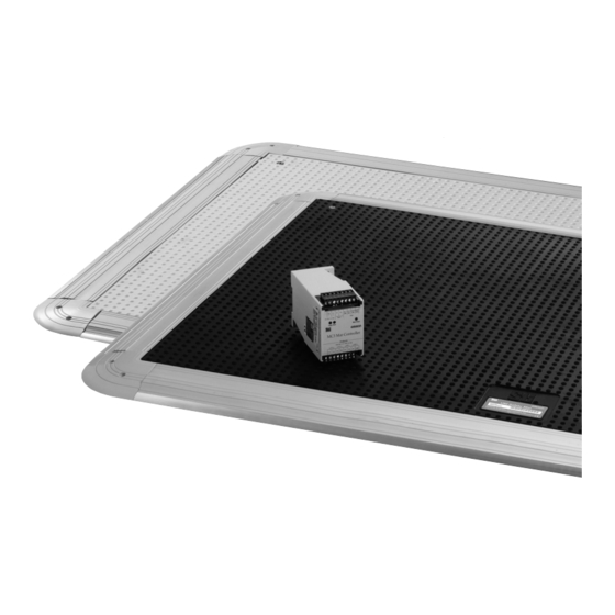
Safety Mat/Safety Mat Controller UM/MC3 Safety Mat That Is Easy to Install and Maintain • Simple connection allows multiple mats to be joined together. • A wide variety of mat sizes are available. • Meets PLd/Safety Category 3 (EN ISO13849-1) requirements when used in combination with the safety controller G9SP or the safety mat controller MC3. - Page 5 UM/MC3 Trims Appearance Name Model Remarks Ramp Trim with Yellow PVC Installed on the perimeter of the Safety Mat. Each UMRT4 Cover (1.22 m) Trim is composed of two parts, an aluminum base and a PVC Cover. Possible to install cables in- Ramp Trim with Yellow PVC UMRT8 side.
-
Page 6: Specifications Ratings
UM/MC3 Specifications Ratings Safety Mat Controller Power input Item Model Power voltage 24 VDC Operating voltage range -15% to +15% of rated supply voltage Power consumption * 3 W max. * Power consumption of loads is not included. Switch Item Model 6 A at 230 VAC/6 A at 24 VDC (resistive load) Rated load... -
Page 7: Installation
UM/MC3 Installation Using Trim Pieces Example 2: Using three Safety Mats Ramp Trim with Yellow PVC Cover: UMRT4/UMRT8 UMOC Secures the edges of the Safety Mats to the floor. It is composed of two parts with an aluminum base and a PVC Cover. Joining Trim: UMJS4/UMJS8 The Joining Trims join the Safety Mats when two or more Safety Mats UMYM5-1000-1000... - Page 8 UM/MC3 Wiring of Safety Mat and Safety Mat Controller Example 1: Using a Single Safety Mat Example 2: Using Two Safety Mats Safety Mat Safety Mat Panel-mount Panel-mount Connector Y Connector Connector UMPMC UM-Y-2-1 UMPMC Safety Mat Controller Note: You can cut a Safety Mat's cable and wire it to the MC3 Safety Mat Controller without using UMPMC.
- Page 9 UM/MC3 Connections Internal Connection Power Control Circuit supply Wiring of Inputs and Outputs Signal name Terminal name Description of operation Wiring Connect the power supply plus (24 VDC) to the Y1 Power supply input terminals for MC3 Power supply terminal. Y1, Y2 input Connect the power source to the Y1 and Y2 terminals.
- Page 10 UM/MC3 Dimensions (Unit: mm) Safety Mat Controller Terminal/LED arrangements Y1 X1 X2 M11 M12 M21 M22 LED (red) LED (green) Stop Lights when the safety Lights when the UM Mat Clear output from the MC3 Safety Mat is not Safety Mat Controller is being activated (i.e., when intrusion is not being detected)
- Page 11 UM/MC3 Accessories Distribution Box Mounting hole dimensions UMDB-6 101.6 MAT3 MAT4 38.1 228.6 215.9 MAT2 MAT5 217.4 38.1 MAT1 MAT6 60.5 38.1 115.8 78.2 75.7 38.1 50.8 Y Connector Panel-mount Connector UM-Y-2-1 UMPMC Pin arrangement Internal wiring 1 (Brown) 2 (White) Female B 4 (Black) 3 (Blue)
-
Page 12: Application Examples
Model Stop category Reset safety category Safety Mat UM series PLd/3 equivalent Manual Mat Controller MC3 Note: The above PL is only the evaluation result of the example. The PL must be evaluated in an actual application by the customer after confirming the usage conditions. - Page 13 Highest achievable PL/ Model Stop category Reset safety category Safety Mat UM series PLd/3 equivalent Mat Controller MC3 Auto Safety Relay Unit G9SA-301 Note: The above PL is only the evaluation result of the example. The PL must be evaluated in an actual application by the customer after confirming the usage conditions.
-
Page 14: Safety Precautions
UM/MC3 Safety Precautions Before installing and using the Safety Mat System, carefully read the instruction manual attached to the product. Precautions for Safe Use !WARNING Serious injury may occur due to breakdown of safety • Turn OFF the power supply before wiring. Also, do not touch any terminals (current-carrying parts) while the power is ON. -
Page 15: Safety Category
Precautions for Correct Use Use of air valve Make sure to use the Safety Mat UM series in combination with the Safety Mat Controller MC series or the Safety Controller G9SP. 1. After installing a mat, loose the air valve on the surface of the mat... - Page 16 MEMO...
- Page 17 MEMO...
- Page 18 MEMO...
-
Page 19: Terms And Conditions Agreement
Data presented in Omron Company websites, catalogs and other materials is provided as a guide for the user in determining suitability and does not constitute a warranty. It may represent the result of Omron’s test conditions, and the user must correlate it to actual application requirements. - Page 20 The Netherlands CA 94555 U.S.A. Tel: (31)2356-81-300/Fax: (31)2356-81-388 Tel: (1) 510-608-3400/Fax: (1) 510-744-1442 © OMRON Corporation 2008-2017 All Rights Reserved. OMRON (CHINA) CO., LTD. OMRON ASIA PACIFIC PTE. LTD. In the interest of product improvement, Room 2211, Bank of China Tower, No.
Need help?
Do you have a question about the UM Series and is the answer not in the manual?
Questions and answers