
Related Manuals for Omron UM Series


Summary of Contents for Omron UM Series
- Page 1 Authorised Distributors:- Intech Systems Chennai Pvt. Ltd, Chennai-600 032 Ph: 4353 8888 Mob: 99 4353 8888 Fax: 044 4353 7888 E-mail: info@intechchennai.com Website: www.intechchennai.com...
-
Page 3: Ordering Information
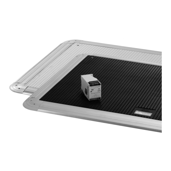
Safety Mat/Safety Mat Controller UM/MC3 New Safety Mat That Is Easy to Install and Maintain • Meets Safety Category 3 (EN954-1) requirements when used in combination with a dedicated controller. • Simple connection allows multiple mats to be joined together. •... - Page 4 UM/MC3 Trims Appearance Name Model Remarks Ramp Trim with Yellow PVC Cover UMRT4 Installed on the perimeter of the Safety Mat. (1.22 m) Each Trim is composed of two parts, an alumi- num base and a PVC Cover. Possible to install Ramp Trim with Yellow cables inside.
-
Page 5: Specifications Ratings
UM/MC3 Specifications Ratings Safety Mat Controller Power input Item Model Power voltage 24 VDC Operating voltage range -15% to +15% of rated supply voltage Power consumption * 3 W max. * Power consumption of loads is not included. Switch Item Model 6A at 250 VAC/6A at 24 VDC (resistance load) Rated load... -
Page 6: Installation
UM/MC3 Installation Using Trim Pieces Example 2: Using three Safety Mats Ramp Trim with Yellow PVC Cover: UMRT4/UMRT8 UMOC Secures the edges of the Safety Mats to the floor. It is composed of two parts with an aluminum base and a PVC Cover. Joining Trim: UMJS4/UMJS8 UMYM5-1000-1000 The Joining Trims join the Safety Mats when two or more Safety Mats... - Page 7 UM/MC3 Wiring of Safety Mat and Safety Mat Controller Example 1: Using a Single Safety Mat Panel-mount Connector UMPMC Safety Mat Safety Mat Controller Note: You can cut a Safety Mat's cable and wire it to the MC3 Safety Mat Controller without using UMPMC. Example 2: Using Two Safety Mats Panel-mount Connector Y Connector...
- Page 8 UM/MC3 Connections Internal Connection Power Control Circuit supply Wiring of Inputs and Outputs Signal name Terminal name Description of operation Wiring Connect the power supply plus (24 VDC) to the Y1 Power supply input terminals for MC3 Power supply terminal. Y1, Y2 input Connect the power supply minus (GND) to the Y2...
- Page 9 UM/MC3 Trims Ramp Trim with Yellow PVC Cover Molded Outside Corner UMRT@ UMOC 58.4 30.6 28.6 72.4 91.4 94.6 58.4 Joining Trim 30.6 UMJS@ 72.4 94.6 Molded Inside Corner 23.1 UMIC 57.5 101.6 21.9 Aluminum Ramp Trim 72.4 UMAL 94.6 13.7 57.5 7.6 10.6...
- Page 10 UM/MC3 Accessories Distribution Box Mounting hole dimensions UMDB-6 60.5 UMDB-6 Universal Mat Distribution Box Scientific Technologies Inc. Fremont. CA USA 101.6 Tel: 510/608-3400. Fax: 510/744-1442 www.sti.com MAT3 Mat 3 Mat 4 MAT4 38.1 228.6 215.9 MAT2 MAT5 Mat 2 Mat 5 217.4 38.1 MAT1...
-
Page 11: Application Examples
UM/MC3 Application Examples MC3 + UM@ (Manual Reset) 24VDC Feedback Loop Power Control Circuit supply Black Brown S1: Reset switch KM and KM2: Magnetic Contactor M: 3-phase motor Blue White Black Brown Blue White Note: 1. The circuit in this example is equivalent to a Safety Category 3 circuit. 2. -
Page 12: Safety Precautions
UM/MC3 Safety Precautions Before installing and using the Safety Mat System, carefully read the instruction manual attached to the product. Warning Precautions for Safe Use Serious injury may occur due to breakdown of safety • Turn OFF the power supply before wiring. Also, do not touch any terminals (current-carrying parts) while the power is ON. - Page 13 Precautions for Correct Use Use of air valve Make sure to use the Safety Mat UM series in combination with the Safety Mat Controller MC series. 1. After installing a mat, loose the air valve on the surface of the mat...
- Page 14 Warranty and Limitations of Liability WARRANTY OMRON’s exclusive warranty is that the products are free from defects in materials and workmanship for a period of one year (or other period if specified) from date of sale by OMRON. OMRON...
- Page 15 OMRON EUROPE B.V. Room 2211, Bank of China Tower, Wegalaan 67-69-2132 JD Hoofddorp 200 Yin Cheng Zhong Road, © OMRON Corporation 2008 All Rights Reserved. The Netherlands PuDong New Area, Shanghai, 200120, China In the interest of product improvement, Tel: (31)2356-81-300/Fax: (31)2356-81-388 Tel: (86) 21-5037-2222/Fax: (86) 21-5037-2200 specifications are subject to change without notice.
Need help?
Do you have a question about the UM Series and is the answer not in the manual?
Questions and answers