Table of Contents
Advertisement
Quick Links
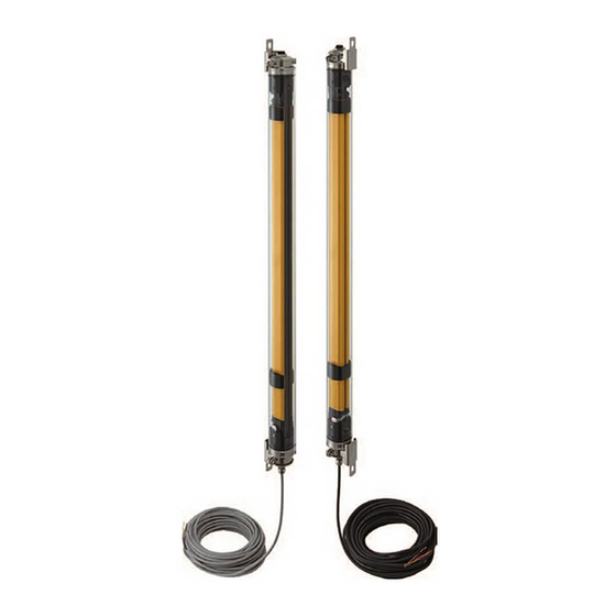
Safety Light Curtain F3SG-SR-K Series
Quick Installation Manual
OMRON Corporation
© OMRON Corporation 2020 All Rights Reserved.
Document Title
Safety light Curtain F3SG-SR Series
Safety Multi-Light Beam F3SG-PG Series
User's Manual
Introduction
Thank you for purchasing the F3SG-SR-K Series Safety Light Curtain (hereinafter referred to as the "F3SG-SR-
K").
The F3SG-SR-K series is an IP69K model safety light curtain intended to be used for humans protection.
This document contains simple instructions to install the F3SG-SR-K.
Please download the F3SG-SR/PG User's Manual for full contents of the instructions from the website. For
details, refer to your local Omron website.
Table of Contents
1. What is Included ...............................................................................................................................2
2. System Components ........................................................................................................................2
3. Setup Procedure Example ...............................................................................................................3
4. Entire Circuit Diagram ......................................................................................................................3
5.Wiring Examples ...............................................................................................................................4
5-1. Non Muting System Wiring Example (Auto Reset Mode with EDM Unused) ............................ 4
5-2. Muting System Wiring Examples (Standard Muting Mode/Exit-Only Muting mode) ..................4
6. Mounting and Beam Alignment ........................................................................................................5
6-1. Mutual Interference Prevention ................................................................................................5
6-2. Distance from Reflective Surfaces ...........................................................................................5
6-3. Safety Distance ........................................................................................................................6
6-4. Mounted with IP69K Model Mounting Bracket (F39-LSGTB-K) ...............................................7
7. Pre-Operation Checklists / Maintenance Checklists....................................................................... 12
Suitability for Use/Contact Information ...............................................................................................16
Man.No.
Z405-E1
2871537-9A
Advertisement
Chapters
Table of Contents

Related Manuals for Omron F3SG-SR-K Series


Summary of Contents for Omron F3SG-SR-K Series
-
Page 1: Table Of Contents
Thank you for purchasing the F3SG-SR-K Series Safety Light Curtain (hereinafter referred to as the "F3SG-SR- K"). The F3SG-SR-K series is an IP69K model safety light curtain intended to be used for humans protection. This document contains simple instructions to install the F3SG-SR-K. -
Page 2: What Is Included
1. What is Included Product Quantity F3SG-SR---K main unit Emitter x 1, Receiver x 1 Factory Default Settings Feature Factory Default Setting Interlock Auto Reset Mode enabled EDM (External Device Monitoring) Disabled Safety output information Auxiliary Output (Inverted signal output: Enable) Muting Standard Muting Mode Override... -
Page 3: Setup Procedure Example
3. Setup Procedure Example Setup ..page 3 Wiring ..page 5 Mounting ..page 12 Operation check Done * For settings with DIP Switch or SD Manager 3, refer to F3SG-SR/PG Series User's Manual. Wiring Mounting Operation check... -
Page 4: Wiring Examples
Wiring Mounting Operation check 5.Wiring Examples 5-1. Non Muting System Wiring Example (Auto Reset Mode with EDM Unused) Function Setting EDM Disabled (factory default setting) Interlock Auto Reset (factory default setting) Long : Open the OPERATING RANGE Operating Range SELECT INPUT line of the emitter or connect Selection the line to 24 VDC. -
Page 5: Mounting And Beam Alignment
Wiring Mounting Operation check 6. Mounting and Beam Alignment 6-1. Mutual Interference Prevention Step1 When two or more F3SG-SR/PG systems are mounted in close proximity to each other, precautions should Check be taken to avoid one system interfering with another, such as by beam alignment, back-to-back configura- position tion, physical barrier, Scan Code Selection, Operating Range Selection or adjusting the distances from adja- cent safety light curtains. -
Page 6: Safety Distance
Wiring Mounting Operation check 6-3. Safety Distance Safety distance (S) Safety Distance Formulas according to ISO 13855/EN ISO 13855 ■ Detection Zone Orthogonal to Direction of Approach Step1 S = K x T + C . . . Formula (1) Check position •... -
Page 7: Mounted With Ip69K Model Mounting Bracket (F39-Lsgtb-K)
Wiring Mounting Operation check 6-4. Mounted with IP69K Model Mounting Bracket (F39-LSGTB-K) ■ Dimensions (Check position) Step1 [Backside mounting] Check position IP69K Model 2-M8 Mouting Bracket Step2 Mount 60 dia. IP69K Model Mouting Bracket [ Unit : mm ] 4-digit number of the type name Dimension C (Protective height: ) F3SG-SR-14... - Page 8 Wiring Mounting Operation check ■ Mounting Securely tighten the screws to fix the separately sold bracket (F39-LSGTB-K) to the mounting position of the Step1 wall surface (Fig. 1) Check position Step2 Mount Align in the same line Fig. 1 Screws to mount the brackets to the wall are not included. •...
- Page 9 Wiring Mounting Operation check Fit the groove of the sensor's cap to the bracket (2), mount the bracket (1), and tighten the alignment screws until the sensor no longer drops (Fig. 3). Step1 Bracket (2) Check position Temporarily tighten Step2 Alignment screws Mount...
- Page 10 Wiring Mounting Operation check Securely tighten the beam alignment screws to fix the sensor housing. The recommended torque to tighten these screws is 3.0 N•m (Fig. 5). Step1 Securely Check tighten position Alignment Step2 screws Mount Securely tighten Alignment screws Fig.
- Page 11 Wiring Mounting Operation check ■ Proper Mounting (Proper Mounting Orientation) Mount the emitter and receiver so that the detection surfaces of the emitter and receiver face in parallel to each other as shown below. The detection surfaces of the emitter and receiver not in parallel to each other or Step1 misaligned may fail to operate properly.
-
Page 12: Pre-Operation Checklists / Maintenance Checklists
Wiring Mounting Operation check 7. Pre-Operation Checklists / Maintenance Checklists After wiring, mounting and beam alignment are done, check the operation of the F3SG-SR-K. Pre-Operation Checklists After installation, the highest level administrator must use the following checklist to verify the operation, plac- ing a check mark in each of the boxes. - Page 13 Wiring Mounting Operation check output, 0 VDC line of the power supply must not be grounded. Wiring must not be bent, cracked, nor damaged. - Operation Check While the Machine Is Stopped The test rod is not deformed. The object resolution may vary depending on the models of the F3SG-SR-K and settings of the Floating Blanking function or Reduced Resolution function.
- Page 14 Wiring Mounting Operation check - Checking that Hazardous Parts Stop While the Machine Operates The hazardous parts stop immediately when a test rod is inserted into the detection zone at 3 positions: "directly in front of the emitter", "directly in front of the receiver", and "between the emitter and receiver". (Use the appropriate test rod.) ...
- Page 15 Wiring Mounting Operation check The hazardous parts stop when the power of the F3SG-SR-K is turned OFF while nothing is in the detection zone. - Items to Inspect Every 6 Months or When Machine Settings Are Changed In addition to inspection item at operation start, following items must also be verified. ...
-
Page 16: Suitability For Use/Contact Information
Suitability for Use/Contact In formation Suitability for Use Omron Companies shall not be responsible for conformity with any standards, codes or regulations which apply to the combination of the Product in the Buyer’s application or use of the Product. At Buyer’s request, Omron will provide applicable third party certification documents identifying ratings and limitations of use which apply to the Product. - Page 17 セーフティ ライ ト カーテン F3SG-□SR-K シ リ ーズ クイックインストールマニュアル 2871537-9A © OMRON Corporation 2020 All Rights Reserved. マニュアル名称 マニュアル番号 セーフティライトカーテン形F3SG-SRシリーズ マルチビームセーフティセンサ 形F3SG-PGシリーズ SGFM-726 ユーザーズマニュアル はじめに このたびはセーフティライトカーテン形 F3SG- □ SR-K シリーズ ( 以下形 F3SG-SR-K と呼びます ) をお買 い上げいただき、ありがとうございます。 形 F3SG-SR-K シリーズは人体の保護を目的としたセーフティライトカーテンの IP69K モデルです。本書は...
-
Page 18: 同梱物のご確認
1. 同梱物のご確認 製品 数量 形F3SG-□SR□□□□□-□□-□-K本体 投光器×1、受光器×1 出荷時設定 機能 出荷時設定 インターロック オートリセットモード 外部リレーモニタ(EDM) 無効 制御出力情報 補助出力 (出力反転機能:有効) ミューティング 標準ミューティングモード オーバーライド 有効 詳細についてはF3SG-SR/PGシリーズユーザーズマニュ アルを参照してください。 トラブルシューティングステッカ 取扱説明書 クイックインストールマニュアル 定格/性能、入出力回路、LED表示灯の点灯パターン、トラブルシューティングについては、形F3SG-SR/PGシリーズユー ザーズマニュアルを参照してください。 2. 各部の名称 <投光器> 投光器 光軸センターライ ンマーク <受光器> 受光器 光軸 投光/受光 位置 表示灯 表示灯名 形F3SG-SRB ま... -
Page 19: セットアップ手順
3. セットアップ手順 セットアップ ..3 ページ 配線 ..5 ページ 取りつけ ..9 ページ 動作チェック おわり * インテリジェントタップの DIP-SW・SD Manager 3 を使用した設定については、形 F3SG-SR/PG シリーズユーザーズマニュアル を参照してください。 配線 取り付け 動作チェック 4. 入出力回路図 (全体回路図) 形... -
Page 20: 配線例
配線 取り付け 動作チェック 5. 配線例 5-1. ミューティングを使用しない配線例 (オートリセットモード、EDM 未使用) 受 投 機能 設定方法 光 光 外部リレーモニタ 器 器 EDM無効:工場出荷時設定 (EDM) インターロック オートリセット:工場出荷時設定 ロングモード:投光器 検出距離選択入 検出距離変更 力線をオープンまたはDC24Vに接続 NPN設定時の配線*1 ミューティング不使 配線図に従って接続 用 DC24V 投光器のテスト入力線を投光器の0V/ 外部テスト不使用 24V線に接続 投光器および受光器の通信線を接続し 光同期 ない DC24V *1. NPN設定時は電源の極性を反転させて配線してください。接続 するセーフティコントローラはPNPまたはNPNの動作モードに 対応する機器を選定してください。... -
Page 21: 取り付け
配線 取り付け 動作チェック 6. 取り付け 6-1. IP69K モデル取付金具(形 F39-LSGTB-K)を取り付ける場合 ■外形寸法図(取り付け位置確認) [ 背面取りつけ時 ] IP69Kモデル取付金具 (形F39-LSGTB-K) 2-M8 IP69Kモデル取付金具 [ 単位 : mm ] (形F39-LSGTB-K) 寸法C 形式中の4桁の数字(検出幅:△) 形F3SG-□SR□△△△△-14 寸法D C-20 形F3SG-□SR□△△△△-25 寸法H C+170 寸法I C+200 ・外形寸法図に記載されている規定の数量、位置に従って金具を使用してください。規定に満たない場合、定格/性能を満た すことができません。 ・センサ本体に加重がかかるようなご使用をされる場合は、金具を追加してください。 F3SG-SR-K クイックインストールマニュアル... - Page 22 配線 取り付け 動作チェック ■取付方法 別売りの取付金具(形F39-LSGTB-K)を、壁面の取り付け位置にねじでしっかりと固定します。 (図1) 直線上に並べる 図1 ・壁面との取付ねじは付属していません。 取付金具の光軸調整用ねじ (六角穴付きねじ (M5×15) ) を緩め、 取付金具 (1) を外します。 (図2) 緩める 光軸調整用ね じ (六角穴付ね じ(M5×15)) 取付金具(1) 緩める 光軸調整用ね じ (六角穴付ね じ(M5×15)) 取付金具(1) 図2 F3SG-SR-K クイックインストールマニュアル...
- Page 23 配線 取り付け 動作チェック 取付金具(2)にセンサのキャップ部溝をはめ、取付金具(1)を取り付けてセンサが脱落しない ところまで光軸調整用ねじを締めます。 (図3) 取付金具(2) 仮締め 光軸調整用ねじ キャップ部溝 取付金具(2) 仮締め 光軸調整用ねじ キャップ部溝 図3 センサの投光器と受光器の電源を入れ、光軸調整を行います。 図4 ・角度調整範囲に制約はありません。 F3SG-SR-K クイックインストールマニュアル...
- Page 24 配線 取り付け 動作チェック 光軸調整用ねじを本締めし、センサの筐体を固定します。光軸調整用ねじの推奨締め付けトルク は、3.0N・mです。 (図5) 本緩め 光軸調整用ねじ 本緩め 光軸調整用ねじ 図5 ・推奨値を大きく超えるトルクで固定すると故障の原因になります。 F3SG-SR-K クイックインストールマニュアル...
-
Page 25: 動作チェック
取り付け 動作チェック 7. 動作チェック 終端キャップ設定、配線、取り付け・光軸調整が終わったら、形 F3SG-SR-K の動作チェックを実施してくださ い。 必要に応じて添付のトラブルシューティングステッカを形 F3SG-SR-K の近くに貼ってください。 MAINT OSSD LONG OSSD MAINT トラブルシューティング方法については、形F3SG-SR/PGシリーズユーザーズマニュアルも参照してください。 http://www.fa.omron.co.jp ご承諾事項 / お問い合わせ先 当社商品は、一般工業製品向けの汎用品として設計製造されています。従いまして、次に掲げる用途での使用を意図しておらず、お客様 が当社商品をこれらの用途に使用される際には、当社は当社商品に対して一切保証をいたしません。ただし、次に掲げる用途であっても 当社の意図した特別な商品用途の場合や特別の合意がある場合は除きます。 (a) 高い安全性が必要とされる用途(例:原子力制御設備、燃焼設備、航空・宇宙設備、鉄道設備、昇降設備、娯楽設備、医用機器、安 全装置、その他生命・身体に危険が及びうる用途) (b) 高い信頼性が必要な用途(例:ガス・水道・電気等の供給システム、24 時間連続運転システム、決済システムほか権利・財産を取扱 う用途など) (c) 厳しい条件または環境での用途 (例 : 屋外に設置する設備、 化学的汚染を被る設備、 電磁的妨害を被る設備、 振動 ・ 衝撃を受ける設備など) (d) カタログ等に記載のない条件や環境での用途 * (a) から (d) に記載されている他、本カタログ等記載の商品は自動車(二輪車含む。以下同じ)向けではありません。自動車に搭載する...
Need help?
Do you have a question about the F3SG-SR-K Series and is the answer not in the manual?
Questions and answers