Table of Contents
Advertisement
Quick Links
This document provides information mainly for selecting suitable models. Please read the Instruction Sheet carefully for information that the user must understand and accept before
purchase, including information on warranty, limitations of liability, and precautions.
OMRON Corporation
Industrial Automation Company
Application Sensors Division
Sensing Devices and Components Division H.Q.
Shiokoji Horikawa, Shimogyo-ku,
Kyoto, 600-8530 Japan
Tel: (81)75-344-7068/Fax: (81)75-344-7107
Regional Headquarters
OMRON EUROPE B.V.
Sensor Business Unit,
Carl-Benz-Str. 4, D-71154 Nufringen,
Germany
Tel: (49)7032-811-0/Fax: (49)7032-811-199
OMRON ELECTRONICS LLC
1 East Commerce Drive, Schaumburg, IL 60173
U.S.A.
Tel: (1)847-843-7900/Fax: (1)847-843-8568
OMRON ASIA PACIFIC PTE. LTD.
83 Clemenceau Avenue,
#11-01, UE Square,
239920 Singapore
Tel: (65)6835-3011/Fax: (65)6835-2711
OMRON CHINA CO., LTD. BEIJING OFFICE
Room 1028, Office Building,
Beijing Capital Times Square,
No. 88 West Chang'an Road,
Beijing, 100031 China
Tel: (86)10-8391-3005/Fax: (86)10-8391-3688
Cat. No. Z217-E1-01
Authorized Distributor:
Printed in Japan
0105
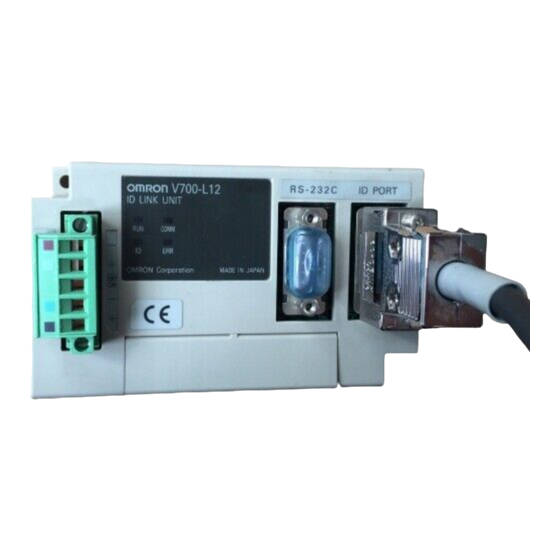
ID Link Unit
V700-L12
User's Manual
Cat.No. Z217-E1-01
Advertisement
Table of Contents

Related Manuals for Omron V700-L12


Summary of Contents for Omron V700-L12
- Page 1 OMRON ASIA PACIFIC PTE. LTD. 83 Clemenceau Avenue, #11-01, UE Square, 239920 Singapore Tel: (65)6835-3011/Fax: (65)6835-2711 OMRON CHINA CO., LTD. BEIJING OFFICE Room 1028, Office Building, Beijing Capital Times Square, No. 88 West Chang'an Road, Beijing, 100031 China Tel: (86)10-8391-3005/Fax: (86)10-8391-3688 Cat.No.
- Page 2 Introduction Thank you for purchasing the OMRON V700-L12 ID Link Unit. We hope you fully utilize this product and its performance for many years to come. • To ensure safety, read this manual carefully before using the V700-L12. In addition, keep this...
- Page 3 Application Considerations (Read and understand this information first.) Introduction Provides information on multidrop connections. Section 1 Provides information on installation and connection. Section 2 Provides information on communications. Section 3 Appendix Section 4 ID Link Unit User's Manual V700-L12...
-
Page 4: Introduction
WARRANTY OMRON’s exclusive warranty is that the products are free from defects in materials and workmanship for a period of one year (or other period if specified) from date of sale by OMRON. OMRON MAKES NO WARRANTY OR REPRESENTATION, EXPRESS OR IMPLIED, REGARDING NON-INFRINGEMENT, MERCHANTABILITY, OR FITNESS FOR PARTICULAR PURPOSE OF THE PRODUCTS. -
Page 5: Meanings Of Signal Words
The GR (frame ground) terminal is in the multi-connection port. Always ground the multi-connection port to 100 Ω or less, regardless of whether it is used or not. Performance may deteriorate if the port is not ground. V700-L12 User’s Manual... -
Page 6: Precautions For Safe Use
• Do not allow water, wires, or any other foreign material to enter through the gaps in the case. Doing so may cause fire or electric shock. • Do not attempt to disassemble, repair, or modify the product. • When disposing of the product, treat it as industrial waste. V700-L12 User’s Manual... -
Page 7: Precautions For Correct Use
2. To prevent damage from static electricity, use a wrist strap or another device for pre- venting electrostatic charges when touching terminals or signal lines. ■ Cleaning Do not clean the product with thinners, benzene, or other organic solvents. These will dissolve the resin parts and coating on the case. V700-L12 User’s Manual... -
Page 8: How To Read This Manual
Link Unit Returns data Finishes reading data Once wiring has been completed, check that all wiring is correct. Incorrect wiring may cause malfunction. V700-L12 V700-L12 User's Manual User's Manual Supplementary information The following symbols indicate useful information and reference pages. - Page 9 Introduction ■ Meanings of Symbols Indicates particularly important points related to a function, including precautions and application advice. Indicates page numbers containing relevant information. Indicates reference to helpful information and explanations for difficult terminology. V700-L12 User’s Manual...
-
Page 10: Table Of Contents
Multidrop Connection Example RFID System/Barcode Reader Settings Link Unit Settings Operation Flowchart Section 2 Installing and Connecting Link Units Nomenclature Power Supply Wiring Connecting to the Host Section 3 Communications DIP Switch Settings Communications Interface Communications Format V700-L12 User’s Manual... - Page 11 Introduction Section 4 Appendix Troubleshooting Error Codes Specifications and External Dimensions Revision History V700-L12 User’s Manual...
- Page 12 V700-L12 User’s Manual...
-
Page 13: Section 1 Multidrop Connections
Section 1 Multidrop Connections Multidrop Connection Example RFID System/Barcode Reader Settings Link Unit Settings Operation Flowchart V700-L12 User's Manual... -
Page 14: Multidrop Connection Example
The connection configuration depends on the interface used at the host (RS-485 or RS-232C). The following connection example is for ID Link Units (“Link Units”) connected to the host using RS-485. The RFID Reader Writer or barcode reader can be supplied with 5-V power from the V700-L12. Host IBM PC/AT personal... -
Page 15: Rfid System/Barcode Reader Settings
8 bits (Use initial setting.) Parity Even Stop bits 1 bit (Use initial setting.) Header None (Use initial setting.) Footer (Use initial setting.) RS/CS control None Read failure processing Sends ?[CR] or >[CR] Other settings Use factory settings V700-L12 User's Manual... -
Page 16: Link Unit Settings
Note: In this connection example, the terminating resistance is ON for the Unit with unit number 3 and the host (Interface Converter). Refer to page 18 and 19 for details on specifications and wiring of Link Units. V700-L12 User's Manual... -
Page 17: Operation Flowchart
Link Units Holds data Holds data Holds data Polling Reads Unit 1 data Link Unit Returns data Polling Reads Unit 2 data Link Unit Returns data Polling Reads Unit 3 data Link Unit Returns data Finishes reading data V700-L12 User's Manual... - Page 18 Sends read command Link Unit Read command executed Returns results/response Unit number 02 Sends read command Link Unit Read command executed Returns results/response Unit number 03 Link Unit Sends read command Read command executed Returns results/response Finishes reading data V700-L12 User's Manual...
-
Page 19: Section 2 Installing And Connecting Link Units
Section 2 Installing and Connecting Link Units Nomenclature Power Supply Wiring Connecting to the Host V700-L12 User's Manual... -
Page 20: Nomenclature
Performance may deteriorate if the port is not ground. Do not disassemble the Unit or touch the internal parts of the Unit while the power is turned ON. Doing so may result in electric shock due to the high-voltage internal parts. V700-L12 User's Manual... -
Page 21: Power Supply Wiring
The terminal block screws are M3. Use crimp terminals suitable for M3screws. Shape Size Forked 6.0 mm max. Round 6.0 mm max. Connect a 24-V power supply. Manufacturer Model OMRON S82K-03024 Once wiring has been completed, check that all wiring is correct. Incorrect wiring may cause malfunction. V700-L12 User's Manual... -
Page 22: Connecting To The Host
Set to unit number 2. Set to unit number 3. Set to unit number 4. DIP switch pin 10: Terminating resistance (ON) No terminating resistance (OFF) No terminating resistance (OFF) Terminating resistance (ON) Total length: 1 km max. V700-L12 User's Manual... - Page 23 No terminating resistance (OFF) Terminating resistance (ON) resistance Total length: 1 km max. Set the host to switch to receive data within 15 ms of data transmission. The system will not operate correctly if this control is not performed. V700-L12 User's Manual...
- Page 24 Section 2 Installing and Connecting Link Units V700-L12 User's Manual...
-
Page 25: Section 3 Communications
Section 3 Communications DIP Switch Settings Communications Interface Communications Format V700-L12 User’s Manual... -
Page 26: Dip Switch Settings
• Connection checked: ON RS-485 terminating resistance OFF (disabled) Connects or disconnects the RS-485 terminating resistance. Set to ON for the Link Units at both ends of the transmission path. (Set to ON if only one Link Unit is connected.) V700-L12 User’s Manual... -
Page 27: Communications Interface
Cable length 15 m max. Communications method Conforms to RS-232C Sync Start-stop synchronization Communications control method OMRON 1:N Baud rate (fixed) 4800, 9600, 19200, or 38400 bps (set using DIP switch) Character format (fixed) Start bits Data bits Parity bit... - Page 28 *1 Ground the shield either at the IBM PC/AT or compatible personal computer or at the Link Unit. *2 A loopback line is required if the CS function is to be used on the personal computer. *3 With wiring method 2, make sure that the cable is connected in the correct direction. V700-L12 User’s Manual...
- Page 29 Total cable length: 1 km max. Communications method Conforms to RS-485 Sync Start-stop synchronization Communications control method OMRON 1:N Baud rate (fixed) 4800, 9600, 19200, or 38400 bps (set using DIP switch) Character format (fixed) Start bits Data bits Parity bit...
- Page 30 MVVS 2CX0.5SQ Tachii Electric Wire Co., Ltd Frame ground line (AWG22 to AWG20 cable) Crimp Connecting one wire to one terminal AI0.5-8WH Phoenix Contact terminals When connecting two wires to one terminal AI-TWIN2×0.5-8WH Crimping tool CRIMPFOX UD6 V700-L12 User’s Manual...
- Page 31 If the connector is difficult to disconnect, hold down the Link Unit and pull the connector. Incorrect disconnec- tion may result in damage to the Unit. V700-L12 User’s Manual...
- Page 32 Power supply Supplied power 5 V ±5% section Communications Communications Conforms to RS-232C section method Sync Start-stop synchronization Communications OMRON 1:1 control method Baud rate (fixed) 9,600 bps Character format Start bits Data bits Parity bit Stop bits Total (fixed) Even...
-
Page 33: Communications Format
Section 3 Communications Communications Format This section describes the commands used for controlling Link Units (for OMRON 1:N protocol.) The interval between each command character must be less than 200 ms during com- munications. Longer intervals will be detected as command delineators. - Page 34 (same as immediately preceding data) ■ Buffer Clear (C) Clears all Link Unit buffers. Input Command (Unit No.) (Check code) $0D Response Refer to page 38 when a code (Unit No.) (Check code) $0D other than 00 is returned. V700-L12 User’s Manual...
- Page 35 The communications frame for the RFID Reader Writer/barcode reader is as follows: Communications data for RFID Reader Writer/barcode reader Control code indicating Control code indicating start of frame end of frame When the power is cycled, the default setting (CR mode) will be used. V700-L12 User’s Manual...
- Page 36 Section 3 Communications V700-L12 User’s Manual...
- Page 37 Section 4 Appendix Troubleshooting Error Codes Specifications and External Dimensions V700-L12 User’s Manual...
- Page 38 • Host send and receive switching timing, when connected to host using RS-485. (Time) Not lit Not lit Not lit Not lit • Check 24 VDC power supply line * The operation indicators turn repeatedly ON and OFF even when commands are not being sent. V700-L12 User’s Manual...
- Page 39 Not lit • Host RS signal control (RS signal is always ON).* Not lit Not lit Not lit Not lit • Check 24-VDC power supply line. Refer to page 25 for information on host connection ports. V700-L12 User’s Manual...
- Page 40 RFID Reader Writer/ • RFID Reader Writer/barcode reader cable wiring (effect of ambient barcode reader noise) communications error RFID Reader Writer/bar- • RFID Reader Writer/barcode reader interface connector connection code reader error • RFID Reader Writer/barcode reader cable disconnection V700-L12 User’s Manual...
- Page 41 Section 4 Appendix Specifications and External Dimensions ■ V700-L12 ID Link Unit (Unit: mm) 41.3 41.5 20.3 35.2 Two, 4.5 dia. Mounting Hole Dimensions Two M4 or 4.2 dia. V700-L12 User’s Manual...
- Page 42 • When data is input from the ID port, it is sent immediately to the host. RS-485 terminating resis- Set to either OFF (disconnected) or ON (connected). tance Use the DIP switch to set or select functions. V700-L12 User’s Manual...
- Page 43 Revision History A manual revision code appears as a suffix to the catalog number at the bottom of the front and rear pages. Cat. No. Z217-E1-01 Revision code Revision code Date Revised contents January 2005 Original production V700-L12 User’s Manual...
Need help?
Do you have a question about the V700-L12 and is the answer not in the manual?
Questions and answers