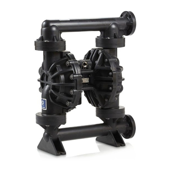
Graco Husky 2200 Repair Parts
Air-operated diaphragm pump
Hide thumbs
Also See for Husky 2200:
- Repair and parts manual (34 pages) ,
- Repair parts (34 pages) ,
- Operation (24 pages)
Table of Contents
Advertisement
Quick Links
Repair/Parts
Husky™ 2200
Husky™
Husky™
Diaphragm Pump
Diaphragm
Diaphragm
Polypropylene or or or PVDF
PVDF pumps
Polypropylene
Polypropylene
PVDF
professional use
use only.
only.
professional
professional
use
only.
Not for
for use
use in in in European
European explosive
Not
Not
for
use
European
Important Safety
Safety Instructions
Important
Important
Safety
Read all warnings and instructions in this manual and in your
Operation manual.
Save
Save
Save these
these
these instructions.
instructions.
instructions.
Maximum Working Pressure: 125 psi
(0.86 MPa, 8.6 bar)
2200 Air-Operated
Air-Operated
2200
Air-Operated
Pump
Pump
pumps for
for fluid
fluid transfer
transfer applications,
pumps
for
fluid
transfer
explosive atmosphere
atmosphere locations.
explosive
atmosphere
Instructions
Instructions
PROVEN QUALITY. LEADING TECHNOLOGY.
applications, including
including high
applications,
including
locations.
locations.
3A2714H
high viscosity
viscosity materials.
materials. For
high
viscosity
materials.
EN
For
For
Advertisement
Table of Contents

Related Manuals for Graco Husky 2200


Summary of Contents for Graco Husky 2200
- Page 1 Repair/Parts Husky™ 2200 2200 Air-Operated Air-Operated Husky™ Husky™ 2200 Air-Operated 3A2714H Diaphragm Pump Pump Diaphragm Diaphragm Pump Polypropylene or or or PVDF PVDF pumps pumps for for fluid fluid transfer transfer applications, applications, including including high high viscosity viscosity materials. materials.
-
Page 2: Table Of Contents
Configuration Number Matrix ....... 7 Manifold Seals ..........30 Troubleshooting..........8 Accessories............31 Repair..............10 Technical Data ........... 32 Pressure Relief Procedure......10 Replace Complete Air Valve ......10 Graco Standard Husky Pump Warranty....34 Replace Seals or Rebuild Air Valve ....11 3A2714H... -
Page 3: Warnings
Warnings Warnings Warnings Warnings The following warnings are for the setup, use, grounding, maintenance, and repair of this equipment. The exclamation point symbol alerts you to a general warning and the hazard symbols refer to procedure-specific risks. When these symbols appear in the body of this manual or on warning labels, refer back to these Warnings. - Page 4 Warnings WARNING WARNING WARNING EQUIPMENT EQUIPMENT EQUIPMENT MISUSE MISUSE HAZARD MISUSE HAZARD HAZARD Misuse can cause death or serious injury. • Do not operate the unit when fatigued or under the influence of drugs or alcohol. • Do not exceed the maximum working pressure or temperature rating of the lowest rated Technical Data Data in all equipment manuals.
- Page 5 Warnings WARNING WARNING WARNING TOXIC TOXIC TOXIC FLUID FLUID OR FLUID OR FUMES FUMES HAZARD FUMES HAZARD HAZARD Toxic fluids or fumes can cause serious injury or death if splashed in the eyes or on skin, inhaled, or swallowed. • Read MSDSs to know the specific hazards of the fluids you are using. •...
-
Page 6: Ordering Information
Please call call your your distributor. distributor. Please Please call your distributor. as needed. 3. Please call Graco Customer Service to order. Related Related Related Manuals Manuals Manuals Manual Title Number 3A2578 Husky 2200 Air-Operated Diaphragm... -
Page 7: Configuration Number Matrix
Configuration Number Matrix Configuration Number Number Matrix Matrix Configuration Configuration Number Matrix Check the identification plate (ID) for the Configuration Number of your pump. Use the following matrix to define the components of your pump. 2200P 2200P - - - PP01AP1PPPTFKPT 2200P PP01AP1PPPTFKPT PP01AP1PPPTFKPT... -
Page 8: Troubleshooting
Troubleshooting Troubleshooting Troubleshooting Troubleshooting Problem Cause Solution Problem Problem Cause Cause Solution Solution Pump cycles but will not prime. Pump is running too fast, causing Reduce air inlet pressure. cavitation before prime. Replace ball and seat. Check valve ball severely worn or wedged in seat or manifold. - Page 9 Troubleshooting Problem Cause Solution Problem Problem Cause Cause Solution Solution Air bubbles in fluid. Suction line is loose. Tighten. Diaphragm (or backup) ruptured. Replace. Loose manifolds, damaged seats or Tighten manifold bolts or replace o-rings. seats or o-rings. Pump cavitation. Reduce pump speed or suction lift.
-
Page 10: Repair
Repair Repair Repair Repair Pressure Relief Relief Procedure Procedure Pressure Pressure Relief Procedure 4. Align the new air valve gasket (105*) on the center housing, then attach the new air valve. Follow the Pressure Relief Procedure Follow the Torque Instructions, page whenever you see this symbol. -
Page 11: Replace Seals Or Rebuild Air Valve
NOTE: Apply lithium-based grease when instructed NOTE: NOTE: to grease. Order Graco PN 111920. 5. Install a retaining ring (210‡) on each end to hold end caps in place. 1. Use all parts in the repair kits. Clean other parts and inspect for damage. - Page 12 Repair 6. Install the o-ring (214♦) on the cup (213♦). Apply a light film of grease to the outside surface of the o-ring and the inside mating surface of the base (212♦). Orient the end of the base that has a magnet toward the end of the cup that has the larger cutout.
-
Page 13: Check Valve Repair
Repair Check Valve Valve Repair Repair Check Check Valve Repair NOTE: NOTE: Kits are available for new check valve balls NOTE: and seats in a range of materials. See page 27 to order kits in the material(s) desired. O-ring and fastener kits also are available. -
Page 14: Diaphragm And Center Section Repair
Repair Diaphragm and and Center Center Section Section Repair Repair Diaphragm Diaphragm Center Section Repair 4. All All Other Other Other Diaphragms Diaphragms Diaphragms a. Orient the pump so one of the fluid covers faces up. Use a 17 mm socket wrench to remove the fluid cover screws (5, 6), then pull NOTE: NOTE:... - Page 15 Repair Reassemble Reassemble Reassemble the the Diaphragm Diaphragm and Diaphragm and Center Center Center Section Section Section Follow all notes in the illustration. These notes e. Grease the shaft u-cups (106*) and the contain important important information. important length and ends of the diaphragm shaft (108*).
- Page 16 Repair SP and and FK FK Models Models PO Models Models Models Models PT Models Models Models Rounded side faces diaphragm Apply lithium based grease. Apply primer and medium-strength (blue) thread locker. Torque to 100-105 ft-lb (136–142 N•m). AIR SIDE markings on diaphragm must face center housing.
- Page 17 Repair 8. To ensure proper seating and extend diaphragm c. Supply a minimum of 20 psi (0.14 MPa, 1.4 life, apply air pressure to the pump prior to bar) air pressure to the air valve. Shop air attaching the second fluid cover. may be used.
-
Page 18: Torque Instructions
Torque Instructions Torque Instructions Instructions Torque Torque Instructions If fluid cover or manifold fasteners have been Inlet and and Outlet Outlet Manifold Manifold Screws Screws Inlet Inlet Outlet Manifold Screws loosened, it is important to torque them using the following procedure to improve sealing. NOTE: Fluid cover and manifold fasteners have a NOTE: NOTE:... -
Page 19: Parts
Parts Parts Parts Parts 3A2714H... - Page 20 Parts Parts/Kits Quick Quick Reference Reference Parts/Kits Parts/Kits Quick Reference Use this table as a quick reference for parts/kits. Go to the pages indicated in the table for a full description of kit contents. Ref. Ref. Ref. Part/Kit Part/Kit Part/Kit Description Description Description...
- Page 21 Parts Center Section Section Center Center Section 2200P - - - PP01AP1PPPTFKPT PP01AP1PPPTFKPT 2200P 2200P PP01AP1PPPTFKPT Sample Sample Sample Configuration Configuration Configuration Number: Number: Number: Pump Fluid Drive Balls Diaphragms Diaphragms Manifold Pump Pump Fluid Fluid Drive Drive Center Center Center Section Section Section...
- Page 22 Parts 2200P 2200P 2200P - - - PP01AP1PPPTFKPT PP01AP1PPPTFKPT PP01AP1PPPTFKPT Sample Configuration Configuration Number: Number: Sample Sample Configuration Number: Pump Fluid Drive Balls Diaphragms Manifold and Seat Center Section Fluid Covers and Seats Size Section Type and Air Valve Manifolds Seals Material 2200...
- Page 23 Parts Air Valve Valve Valve 2200P 2200P - - - PP01AP1PPPTFKPT 2200P PP01AP1PPPTFKPT PP01AP1PPPTFKPT Sample Configuration Configuration Number: Number: Sample Sample Configuration Number: Pump Fluid Drive Center Section Section Fluid Covers Covers and Seats Balls Diaphragms Diaphragms Manifold Manifold and and Seat Seat Pump...
- Page 24 Parts 2200P 2200P 2200P - - - PP01AP1PPPTFKPT PP01AP1PPPTFKPT PP01AP1PPPTFKPT Sample Configuration Configuration Number: Number: Sample Sample Configuration Number: Pump Fluid Drive Balls Diaphragms Manifold and Seat Center Section Fluid Covers and Seats Size Section Type and Air Valve Manifolds Seals Material 2200...
- Page 25 Parts Fluid Covers Covers and and Manifolds Manifolds Fluid Fluid Covers Manifolds 2200P - - - PP01AP1PPPTFKPT PP01AP1PPPTFKPT 2200P 2200P PP01AP1PPPTFKPT Sample Sample Sample Configuration Configuration Configuration Number: Number: Number: Pump Fluid Drive Balls Diaphragms Diaphragms Manifold Pump Pump Fluid Fluid Drive Drive...
- Page 26 Parts Seats and and Check Check Balls Balls Seats Seats Check Balls 2200P - - - PP01AP1PPPTFKPT PP01AP1PPPTFKPT 2200P 2200P PP01AP1PPPTFKPT Sample Sample Sample Configuration Configuration Configuration Number: Number: Number: Pump Fluid Drive Balls Diaphragms Diaphragms Manifold Pump Pump Fluid Fluid Drive Drive...
- Page 27 Parts Diaphragms Diaphragms Diaphragms 2200P 2200P - - - PP01AP1PPPTFKPT 2200P PP01AP1PPPTFKPT PP01AP1PPPTFKPT Sample Configuration Configuration Number: Number: Sample Sample Configuration Number: Pump Fluid Drive Center Section Section Fluid Covers Covers and Seats Balls Diaphragms Diaphragms Manifold Manifold and and Seat Seat Pump Pump...
- Page 28 Parts 2200P 2200P 2200P - - - PP01AP1PPPTFKPT PP01AP1PPPTFKPT PP01AP1PPPTFKPT Sample Configuration Configuration Number: Number: Sample Sample Configuration Number: Pump Fluid Drive Balls Diaphragms Manifold and Seat Center Section Fluid Covers and Seats Size Section Type and Air Valve Manifolds Seals Material 2200...
- Page 29 Parts Seats, Check Check Balls, Balls, and and Diaphragm Diaphragm Kits Kits Seats, Seats, Check Balls, Diaphragm Kits 2200P - - - PP01AP1PPPTFKPT PP01AP1PPPTFKPT 2200P 2200P PP01AP1PPPTFKPT Sample Sample Sample Configuration Configuration Configuration Number: Number: Number: Pump Fluid Drive Balls Diaphragms Diaphragms Manifold Pump Pump...
-
Page 30: Manifold Seals
Parts Manifold Seals Seals Manifold Manifold Seals 2200P - - - PP01AP1PPPTFKPT PP01AP1PPPTFKPT 2200P 2200P PP01AP1PPPTFKPT Sample Sample Sample Configuration Configuration Configuration Number: Number: Number: Pump Fluid Drive Center Section Fluid Covers and Seats Balls Diaphragms Manifold and Seat Size Section Type and Air Valve... -
Page 31: Accessories
Accessories Accessories Accessories Accessories Muffler 111897 111897 Muffler Muffler 111897 Legacy or remote exhaust muffler option. NOTE: NOTE: See NOTE: See DataTrak DataTrak DataTrak Manual Manual 313840 Manual 313840 313840 for: for: for: • Pulse Count Conversion Kits 24B794 and 24B795 •... -
Page 32: Technical Data
Technical Data Technical Data Data Technical Technical Data Husky 2200 2200 Diaphragm Diaphragm Pump Pump Husky Husky 2200 Diaphragm Pump Metric Metric Metric Maximum fluid working pressure 125 psi 0.86 MPa, 8.6 bar Air pressure operating range 20 to 125 psi 0.14 to 0.86 MPa, 1.4 to 8.6 bar... - Page 33 California Proposition 65 Maximum Maximum Maximum pump pump pump speed speed speed 125 cycles per minute Standard diaphragms Overmolded diaphragms 155 cycles per minute Weight Weight Weight Polypropylene 80 lb 36.3 kg PVDF 106 lb 48.1 kg Wetted Wetted Wetted Parts Parts Parts plus the...
-
Page 34: Graco Standard Husky Pump Warranty
With the exception of any special, extended, or limited warranty published by Graco, Graco will, for a period of five years from the date of sale, repair or replace any part of the equipment determined by Graco to be defective. This warranty applies only when the equipment is installed, operated and maintained in accordance with Graco’s written recommendations.
Need help?
Do you have a question about the Husky 2200 and is the answer not in the manual?
Questions and answers