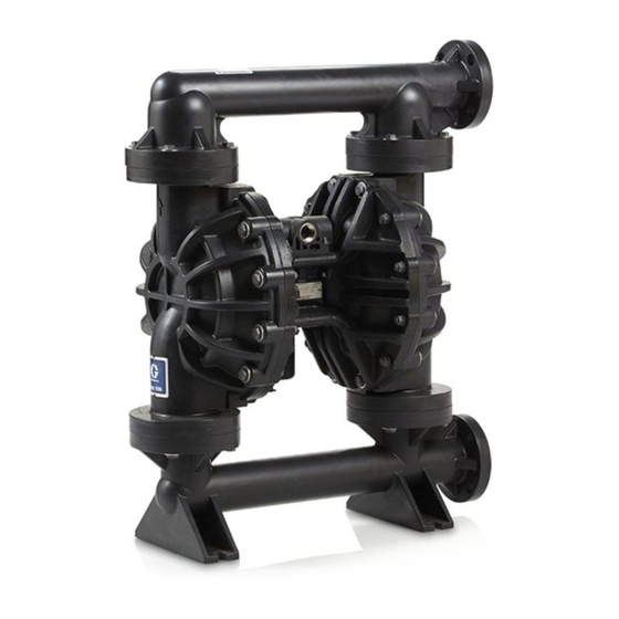
Graco Husky 2200 Operation
Air-operated diaphragm pump
Hide thumbs
Also See for Husky 2200:
- Repair and parts manual (34 pages) ,
- Repair parts (34 pages) ,
- Operation (24 pages)
Table of Contents
Advertisement
Quick Links
Operation
Husky™
Husky™ 2200
Husky™
2200
2200 Air
Diaphragm Pump
Pump
Diaphragm
Diaphragm
Pump
Polypropylene and
and PVDF
PVDF pumps
Polypropylene
Polypropylene
and
PVDF
professional use
use only.
only.
professional
professional
use
only.
Not
Not for
Not
for use
for
use
use in in in European
European explosive
European
Important Safety
Safety Instructions
Instructions
Important
Important
Safety
Instructions
Read all warnings and instructions in this manual and in your
Repair/Parts manual. Save
Maximum Working Pressure: 125 psi
(0.86 MPa, 8.6 bar)
Air - - - Operated
Air
Operated
Operated
pumps for
for fluid
fluid transfer
transfer applications,
pumps
for
fluid
transfer
explosive atmosphere
explosive
atmosphere locations.
atmosphere
locations.
locations.
Save
Save these
these
these instructions.
instructions.
instructions.
PROVEN QUALITY. LEADING TECHNOLOGY.
www.northridgepumps.com
applications, including
including high
high viscosity
applications,
including
high
3A2578E
EN
viscosity materials.
materials. For
For
viscosity
materials.
For
Advertisement
Table of Contents

Related Manuals for Graco Husky 2200


Summary of Contents for Graco Husky 2200
- Page 1 Operation Husky™ Husky™ 2200 Husky™ 2200 2200 Air Air - - - Operated Operated Operated Diaphragm Pump Pump Diaphragm Diaphragm Pump 3A2578E Polypropylene and and PVDF PVDF pumps pumps for for fluid fluid transfer transfer applications, applications, including including high high viscosity viscosity materials.
-
Page 2: Table Of Contents
Air Exhaust Ventilation ......... 11 Dimensions ............18 Fluid Supply Line ......... 11 Performance Charts..........20 Fluid Outlet Line........... 12 Technical Data ........... 22 Flange Connections ........13 Graco Standard Husky Pump Warranty....24 Operation ............14 Pressure Relief Procedure......14 3A2578E www.northridgepumps.com... -
Page 3: Warnings
Warnings Warnings Warnings Warnings The following warnings are for the setup, use, grounding, maintenance, and repair of this equipment. The exclamation point symbol alerts you to a general warning and the hazard symbols refer to procedure-specific risks. When these symbols appear in the body of this manual or on warning labels, refer back to these Warnings. - Page 4 Warnings WARNING WARNING WARNING EQUIPMENT MISUSE MISUSE HAZARD HAZARD EQUIPMENT EQUIPMENT MISUSE HAZARD Misuse can cause death or serious injury. • Do not operate the unit when fatigued or under the influence of drugs or alcohol. • Do not exceed the maximum working pressure or temperature rating of the lowest rated system component.
- Page 5 Warnings WARNING WARNING WARNING BURN HAZARD HAZARD BURN BURN HAZARD Equipment surfaces and fluid that’s heated can become very hot during operation. To avoid severe burns: • Do not touch hot fluid or equipment. PERSONAL PROTECTIVE PROTECTIVE EQUIPMENT EQUIPMENT PERSONAL PERSONAL PROTECTIVE EQUIPMENT...
-
Page 6: Ordering Information
To Order Order Replacement Replacement Parts Parts Order Replacement Parts ordering information, as needed. 3. Please call Graco Customer Service to order. Please Please Please call call call your your your distributor. distributor. -
Page 7: Configuration Number Matrix
Configuration Number Matrix Configuration Number Number Matrix Matrix Configuration Configuration Number Matrix Check the identification plate (ID) for the Configuration Number of your pump. Use the following matrix to define the components of your pump. 2200P- - - PP01AP1PPPTFKPT PP01AP1PPPTFKPT 2200P 2200P PP01AP1PPPTFKPT... -
Page 8: Installation
25 % of the outlet working pressure. selecting and installing system components. Contact 3. Reduce liquid velocity: Slow the cyclic rate of your Graco distributor for assistance in planning a the pump. system to suit your needs. Always use Genuine Graco Parts and accessories. - Page 9 Installation Accessories/Components Not Not Supplied Supplied System Components Components Accessories/Components Accessories/Components Supplied System System Components Air supply line Air inlet port (not visible) Bleed-type master air valve (may be Air exhaust port and muffler required for your pump) Air filter/regulator assembly Fluid inlet port Master air valve (to isolate the Fluid outlet port...
-
Page 10: Ground The System
Installation Ground The The System System Air Lines Lines Ground Ground System Lines 1. Install an air filter/regulator assembly (C). The regulator controls the fluid pressure. The fluid stall pressure will be the same as the setting of the air regulator. The filter removes harmful dirt and moisture from the compressed air supply. -
Page 11: Air Exhaust Ventilation
Installation Air Exhaust Exhaust Ventilation Ventilation Exhaust Ventilation To provide provide provide a a a remote remote remote exhaust: exhaust: exhaust: 1. Remove the muffler (U) from the pump air exhaust port (K). 2. Install a grounded air exhaust hose (S) and If pumping toxic fluids, you must vent the exhaust connect the muffler to the other end of the hose. -
Page 12: Fluid Outlet Line
Installation Fluid Outlet Outlet Line Line Fluid Fluid Outlet Line 2. If the inlet fluid pressure to the pump is more than 25% of the outlet working pressure, the ball check valves will not close fast enough, 1. Use grounded, flexible fluid hoses. See resulting in inefficient pump operation. -
Page 13: Flange Connections
Installation Flange Connections Connections Flange Flange Connections The fluid inlet and outlet ports are 2 in. (50 mm) raised face, ANSI/DIN PN 10 flanges. Connect 2 in. (50 mm) plastic pipe flange to the pump as follows. You will need: •... -
Page 14: Operation
Operation Operation Operation Operation Pressure Relief Relief Procedure Procedure Pressure Pressure Relief Procedure 3. Place the suction tube (if used) in fluid to be pumped. Follow the Pressure Relief Procedure NOTE: If fluid inlet pressure to the pump is more NOTE: NOTE: whenever you see this symbol. -
Page 15: Maintenance
Maintenance Maintenance Maintenance Maintenance Maintenance Maintenance Maintenance Schedule Schedule Schedule Flushing Flushing Flushing and and Storage Storage Storage Establish a preventive maintenance schedule based on the pump’s service history. Scheduled maintenance is especially important to prevent spills or leakage due to diaphragm failure. Lubrication Lubrication Lubrication... -
Page 16: Torque Instructions
Torque Instructions Torque Instructions Instructions Torque Torque Instructions If fluid cover or manifold fasteners have been Inlet Inlet Inlet and and Outlet Outlet Outlet Manifold Manifold Manifold Screws Screws Screws loosened, it is important to torque them using the following procedure to improve sealing. NOTE: NOTE: NOTE: Fluid cover and manifold fasteners have a... -
Page 17: Notes
Notes Notes Notes Notes 3A2578E www.northridgepumps.com... -
Page 18: Dimensions
Dimensions Dimensions Dimensions Dimensions End Flange Flange Models, Models, Polypropylene Polypropylene Flange Models, Polypropylene and PVDF PVDF PVDF Polypropylene Polypropylene Polypropylene PVDF PVDF PVDF Polypropylene Polypropylene Polypropylene PVDF PVDF PVDF A A A 25.1 in. 63.8 cm 25.2 in. 64.0 cm G G G 19.8 in. - Page 19 Dimensions Center Flange Flange Models, Models, Polypropylene Polypropylene Center Center Flange Models, Polypropylene Only Only Only Polypropylene Polypropylene Polypropylene Polypropylene Polypropylene Polypropylene A A A 24.1 in. 61.2 cm G G G 18.5 in. 47.0 cm B B B H H H 27.2 in.
-
Page 20: Performance Charts
Performance Charts Performance Charts Charts Performance Performance Charts Bolt Bolt - - - through Bolt through Diaphragms through Diaphragms Diaphragms Fluid Fluid Fluid Pressure Pressure Pressure Approximate Approximate Approximate Cycles Cycles per Cycles per Minute Minute Minute (0.86, 8.6) (0.70, 7.0) (0.52, 5.2) Operating Air Air Pressure... - Page 21 Performance Charts Overmolded Diaphragms Diaphragms Overmolded Overmolded Diaphragms Fluid Pressure Pressure Fluid Fluid Pressure Approximate Cycles Cycles per per Minute Minute Approximate Approximate Cycles Minute (0.86, 8.6) (0.70, 7.0) (0.52, 5.2) Operating Operating Air Operating Air Pressure Pressure Pressure (MPa, bar) bar) (MPa, (MPa,...
-
Page 22: Technical Data
Technical Data Technical Data Data Technical Technical Data Husky Husky Husky 2200 2200 2200 Diaphragm Diaphragm Diaphragm Pump Pump Pump Metric Metric Metric Maximum fluid working pressure 125 psi 0.86 MPa, 8.6 bar Air pressure operating range 20 to 125 psi 0.14 to 0.86 MPa, 1.4 to 8.6 bar... - Page 23 Technical Data Maximum pump pump speed speed Maximum Maximum pump speed Standard diaphragms 125 cycles per minute Overmolded diaphragms 155 cycles per minute Weight Weight Weight Polypropylene 80 lb 36.3 kg PVDF 106 lb 48.1 kg Wetted Parts Parts Wetted Wetted Parts Wetted parts include material(s) chosen for seat, ball, and diaphragm options, plus...
-
Page 24: Graco Standard Husky Pump Warranty
Graco to be defective. This warranty applies only when the equipment is installed, operated and maintained in accordance with Graco’s written recommendations. This warranty does not cover, and Graco shall not be liable for general wear and tear, or any malfunction, damage or wear caused by faulty installation, misapplication, abrasion, corrosion, inadequate or improper maintenance, negligence, accident, tampering, or substitution of non-Graco component parts.
Need help?
Do you have a question about the Husky 2200 and is the answer not in the manual?
Questions and answers