
Related Manuals for Mooreco 91153-A


Summary of Contents for Mooreco 91153-A
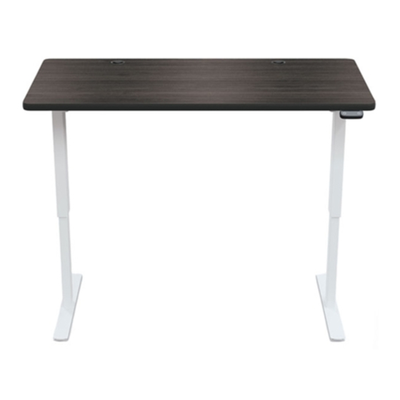
- Page 1 Up-Rite Electric Height Adjust Desk Part Number: 91153-A, 91153-B, 91153-C, 91153-D, 91153-E, 91153-F. ASSEMBLY INSTRUCTIONS INSTRUCCIONES DE ENSEMBLAJE INSTRUCTIONS DE MONTAGE DO NOT THROW AWAY! NO LA TIRE NE PAS JETER UPDATED AS OF: 03/08/18 1 of 10...
- Page 2 HARDWARE PARTS A- (8x) M6-1.0 x10mm B- (8x) M6-1.0 (L+R) (2x) x12mm C- (16x) M6-1.0 x15mm D- (2x) M6-1.0 (L+R) x75mm E- (8x) M6-1.0 x6mm K- (2x) 3/16” Wood Screws (2x) L- (4x) 5/32” Wood Screws H- #2.5 allen wrench (2x) I- #3 allen wrench J- #4 allen wrench...
-
Page 3: Warranty
WARNINGS AND DISCLAIMERS SPANISH TRANSLATION FRENCH TRANSLATION Review full assembly instructions and Previo a comenzar el proceso de Avant de commencer l’ assamblage check that all parts are present before ensamblaje favor revisar veuillez consulter instructions beginning assembly. Heavy or large instrucciones y asegurarse que cuenta con complètes et vérifier si vous avez toutes furniture may require multiple persons in... - Page 4 STEP 1 A- 4x Use 4 “A” screws to install foot to leg upright. Repeat for both legs. STEP 2 Screw glides into foot. Repeat for both legs. UPDATED AS OF: 03/08/18 4 of 10...
- Page 5 STEP 3 Use 4 more “B” screws on each side to further secure Use 4 “B” screws to attach leg assembly to the P3 the leg to crossbar. crossbar. Repeat for both legs. Note: Match L to L and R to R to ensure holes align. B- 4x STEP 4 Slide P5 square tube into leg/crossbar assemblies.
- Page 6 STEP 3 Loosen pre-installed set screws on both hexagonal rods. Slide the pointed end of the hexagonal rods into the round center rod. STEP 4 Slide one end of the hexagonal rod through the motor (P8). Push both ends of the rod assembly into the hole shown in each leg.
- Page 7 STEP 5 Use 2 “D” screws to secure the motor to the frame. D- 2x STEP 6 Align holes in the frame with inserts in the top. Use 8 “C” screws to secure the frame to the table top. NOTE- Ensure the rods remains fully inserted to each leg.
- Page 8 STEP 7 Tighten 8 pre-installed set screws to lock frame position. E- 8x STEP 8 Center the round middle rod and slide the metal ”stops” up against either end. Tighten the two set screws to lock it in place. UPDATED AS OF: 03/08/18 8 of 10...
- Page 9 STEP 11 Use 4 “L” wood screws to install control panel in desired position on the bottom of the top. STEP 12 Use 2 “K” screws to mount the power brick bracket to the bottom of the table in desired location. UPDATED AS OF: 03/08/18 9 of 10...
- Page 10 STEP 13 Use 2 “K” screw to install each plastic cord management clip in desired location. Slide power brick into mount bracket Plug white plug from contol panel into motor through hole in leg bracket. Plug remaining control panel wire into power brick wire.
Need help?
Do you have a question about the 91153-A and is the answer not in the manual?
Questions and answers