
Related Manuals for Pulsar HPSB 3512C


Summary of Contents for Pulsar HPSB 3512C
- Page 1 HPSB 3512C v.1.0 HPSB 13,8V/3A/17Ah Buffer, switch mode power supply unit. Edition: 1’st from 03 th of October 2011 Supercedes the ------------- edition:...
- Page 2 Maximum battery charging current: 0.5 A. Total device current + battery: 3.5 A max. OPTIONAL POWER SUPPLY CONFIGURATIONS: (visualisation available at: www.pulsar.pl) BATTERY 17Ah: 1. Buffer power supply unit HPSB 13,8V/3x1A/17Ah. - HPSB3512C + LB4 3x1,0A (AWZ576 or AWZ575) + 17Ah 2.
- Page 3 BATTERY 7Ah: 1. Buffer power supply unit HPSB 13,8V/12V/6x0,5A/7Ah. - HPSB3512C + RN500 (13,8V/12V) + LB8 6x0,5A (AWZ580 or AWZ578) + 7Ah 2. Buffer power supply unit HPSB 13,8V/2x5V÷7,4V/2x2A/7Ah. - HPSB3512C + 2xDCDC20 (2x5V÷7,4V/2x2A) + 7Ah 3. Buffer power supply unit HPSB 13,8V/5V÷7,4V/4x0,5A/7Ah. - HPSB3512C + DCDC20 (5V÷7,4V) + LB4 4x0,5A (AWZ574 or AWZ576) + 7Ah 1.2 Block diagram Fig.1 Fig.1.
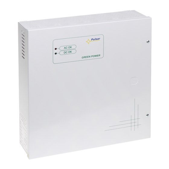
- Page 4 Fig.2. The view of the PSU.
- Page 5 1.4 Technical parameters: - electrical parameters (tab.3) - mechanical parameters (tab.4) - operation safety (tab.5) - operation parameters (tab.6) Electrical parameters (tab. 3) Mains supply 176÷264V AC Current up to 0.6A@230VAC Power frequency 50÷60Hz Supply power 50W max. Efficiency Output voltage 13,8V DC –...
- Page 6 Operating parameters (tab.6) Operating temperature -10ºC...+40ºC (see: chart 1) Storage temperature -20ºC...+60ºC Relative humidity 20%...90%, without condensation Vibrations during operation unacceptable Impulse waves during operation unacceptable Direct insulation unacceptable Vibrations and impulse waves during transport According to PN-83/T-42106 Chart 1. Acceptable output current from the PSU depending on ambient temperature. 2.
- Page 7 The shock protection circuit shall be performed with a particular care, i.e. the yellow and green wire coat of the power cable shall stick to one side of the terminal - marked with ‘ ‘ symbol on the PSU enclosure. Operation of the PSU without the properly made and fully operational shock protection circuit is UNACCEPTABLE! It can cause a device failure or an electric shock.
- Page 8 GENERAL WARRANTY CONDITIONS 1. Pulsar K. Bogusz Sp.j. (the manufacturer) grants a two-year warranty for the equipment, starting from the initial product date of purchase placed on the receipt. 2. If a purchase proof is missing, a three-year warranty period is counted from the device’s production date.
Need help?
Do you have a question about the HPSB 3512C and is the answer not in the manual?
Questions and answers