
Related Manuals for allen WB1824


Summary of Contents for allen WB1824
- Page 1 WB1824 - WORK BRIDGE SAFETY & PARTS MANUAL Manual Part #: 068522 | Revision: - Language: English | Original Instructions...
- Page 2 Allen Engineering Corporation (AEC). AEC assumes no responsibility or liability for any errors or inaccuracies that may appear in this manual.
-
Page 3: General Information Limited Warranty
If Allen chooses to replace the part, it will be at no cost to the customer and will be made available to the Allen Distributor, Dealer, or Rental Center from whom the End User purchased the product. -
Page 4: Table Of Contents
Table of Contents GENERAL INFORMATION Sect Title Page General Information Limited Warranty ......................3 Load Capacity Ratings....................5 Information Contained in This Manual .................6 Dealer Information / Ordering Parts ................7 Model Number - Serial Number Codes ................8 Technical Specifications ....................9 Safety ........................10 Federal / State Warning Regulations .................11 Manual Tag Safety Detail ..................12 Spark Arrestor Notice / Hazard Symbols ..............13... -
Page 5: Load Capacity Ratings
NOT recomended without consulting an AEC product support specialist or Authorized AEC dealer FIRST! Calculations are done without factoring weather. Please note that in adverse weather conditions, capacity ratings need to be decreased. Please contact Allen Engineering PRODUCT SUPPORT with any questions reguarding load capacity. 068522 Page 5... -
Page 6: Information Contained In This Manual
Your engine and clutch is not manufactured by Allen Engineering Corporation, Inc, and there- fore is not covered under Allen Engineering Corporation, Inc warranty. -
Page 7: Dealer Information / Ordering Parts
Ordering Parts Your Dealer has Allen Engineering Corporation trained mechanics and original Allen replace- ment parts. Always contact the Allen Dealer who sold you this machine for Allen Certified repairs and replacement parts. Place Allen Dealer information below for future reference. -
Page 8: Model Number - Serial Number Codes
Model Number / Serial Number GENERAL INFORMATION Manufacturer’s Codes: When ordering parts or requesting service information, you will always be asked to specify the model and serial numbers of the machine. The legends below spe- cifically defines each significant character or group of characters of the Model Number and Serial Number codes. -
Page 9: Technical Specifications
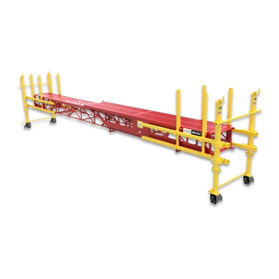
These work bridges are ideal for joint work, applying curing compounds, bull-floating, applying textures or whenever a suitable platform for doing bridge work is required. The Allen Work Bridge is an economical workhorse on any job site. Work Bridge 1824 Dimensions (H x W x L) 18”... -
Page 10: Safety
SECTION 1 SAFETY SECTION 1 SAFETY Page 10 068522... -
Page 11: Federal / State Warning Regulations
Federal / State Warnings SECTION 1 SAFETY RESPIRATORY HAZARDS Grinding/cutting/drilling of masonry, concrete, metal and other materials can generate dust, mists and fumes containing chemicals known to cause serious or fatal injury or illness, such as respiratory disease, cancer, birth defects or other reproductive harm. -
Page 12: Manual Tag Safety Detail
Manual Tag Safety Detail SECTION 1 SAFETY Safety-Alert Signs This manual contains Safety-Alert Signs, as defined below, which must be followed to reduce the possibility of improper servi ce damage to the equipment or personal injury. Read and follow all Safety-Alert Signs included in this manual. -
Page 13: Spark Arrestor Notice / Hazard Symbols
Spark Arrestor Notice / SECTION 1 SAFETY Hazard Symbols Some states require that in certain locations arrestors be used on internal combustion engines. A spark arrester is a device designed to prevent the discharge of spark or flames from the engine exhaust. It is often required when operating equipment on for- ested land to prevent the risk of fires. -
Page 14: Operating Safety
Operating Safety SECTION 1 SAFETY Familiarity and proper training are required for the safe operation of this equipment! Equipment operated improperly or by untrained personnel can be dangerous! Read the operating instructions contained in both this manual and the engine manual and familiarize yourself with the location and proper use of all controls. -
Page 15: Engine Safety
Engine Safety SECTION 1 SAFETY Internal combustion engines present special hazards during operation and fueling. Read and follow the warning instructions in the engine owner’s manual and the safe- ty guidelines below. Failure to follow the warnings and safety guidelines could result in severe injury or death. -
Page 16: Service Safety
Service Safety SECTION 1 SAFETY Poorly maintained equipment can become a safety hazard! In order for the equipment to operate safely and properly over a long period of time, periodic maintenance and occasional repairs are necessary. • ALWAYS disconnect the battery before servicing the equipment. •... -
Page 17: Lifting Safety
Lifting Safety SECTION 1 SAFETY ALWAYS DO A THOROUGH INSPECTION OF THE SLINGS, CHAINS, AND HOOKS BEFORE ATTEMPTING TO LIFT THE MACHINE! OSHA has set forth guidelines which detail the use of Rigging Equipment for Material handling. This guideline is found under OSHA Standard Number: 1926.251 Please read and follow all guidelines found in this standard. - Page 18 Lifting Safety SECTION 1 SAFETY PLEASE CONSULT ON-SITE SAFETY COORDINATOR BEFORE ATTEMPTING TO LIFT MACHINE. IMPROPER RIGGING AND LIFTING CAN RESULT IN INJURY OR DEATH. BELOW IS AN EXAMPLE OF STRAP PLACEMENT AND LIFTING PROCEDURES, BUT THIS SHOULD NOT BE USED AS A GUIDE FOR LIFTING THE MACHINE! (ON LONGER WORKBRIDGES, A SPREADER BEAM MAY BE REQUIRED.) TO CRANE USE A 5,000 lb SHACKLE AS...
-
Page 19: Transportation Safety
Transportation Safety SECTION 1 SAFETY • Make sure the hitch and coupling of the towing vehicle are rated equal to, or greater than the trailer “gross vehicle weight rating.” • ALWAYS inspect the hitch and coupling for wear. Never tow a trailer with defective hitches, couplings, chains, etc. -
Page 20: Assembly
SECTION 2 ASSEMBLY SECTION 2 ASSEMBLY Page 20 068522... -
Page 21: Assembly Instructions
Assembly Instructions SECTION 2 ASSEMBLY Please follow the instuructions below for assembly: Work Bridge Section Connections: Bolt Connecting Pin Hairpin Connecting Clevis Rod End Clevis Pin 1. Align WB sections so that the connecting clevis sits outside the rod end. 2. - Page 22 Assembly Instructions SECTION 2 ASSEMBLY Installing Pneumatic Wheel Type Bracket: Adjustable End Frame Bracket Paving Style Wheel Slide Assembly Workbridge Section Pneumatic Tire Assembly 1. Loosen clip and slide adjustable end frame bracket around workbridge section, and tighten clips back to secure end frame bracket. 2.
- Page 23 Assembly Instructions SECTION 2 ASSEMBLY Installing Power Wheel Option: 1. Place Power Wheel Power Unit on Work Bridge as shown in figure. Power Wheel Power Unit 2. Attach Power Unit with 1/2”-13 x 3-1/2” bolt (045855 x 4) and Nut (011238 x 4) 3.
- Page 24 Assembly Instructions SECTION 2 ASSEMBLY Installing Cable Tension Kit: 1. Loop dead end of cable through the Hook & Eye Turnbuckle. 2. Apply first clip one base width from dead end of wire rope. U-Bolt over dead end. Live end rests in clip saddle.
- Page 25 Assembly Instructions SECTION 2 ASSEMBLY 8. Center the Cable Stay Assembly Mounts on to low frame as shown. 9. Attach cable to Cable Stays on the unit. Be sure that all bolts and nuts are securely fastened before placing any weight on the Work Bridge. 068522 Page 25...
-
Page 26: Parts
SECTION 3 PARTS SECTION 3 PARTS Page 26 068522... -
Page 27: Mainframe Sizes
Mainframe Sizes SECTION 3 PARTS ITEM PART # DESCRIPTION 051679 Assembly, Mainframe, 3 Foot 068639 Assembly, Mainframe, Powered, 3 Foot 051678 Assembly, Mainframe, 6 Foot 068638 Assembly, Mainframe, Powered, 6 Foot 051677 Assembly, Mainframe, 12 Foot 068637 Assembly, Mainframe, Powered, 12 Foot 051680 Assembly, Mainframe, 15-25 Foot Telescoping 068640... -
Page 28: Mainframe Assembly - 3 Foot
Pin, Connecting 051622 Weldment, 3’ Mainframe 051877 Pin, Clevis, 1” For Powered Option also Include: ITEM PART # DESCRIPTION 068632 Kit, Hose and Fitting, WB1824, 3’ Section 051077 Ring, Color, Green, Coding 051078 Ring, Color, White, Coding Page 28 068522... -
Page 29: Mainframe Assembly - 6 Foot
Pin, Connecting 051622 Weldment, 3’ Mainframe 051877 Pin, Clevis, 1” For Powered Option also Include: ITEM PART # DESCRIPTION 068631 Kit, Hose and Fitting, WB1824, 6’ Section 051077 Ring, Color, Green, Coding 051078 Ring, Color, White, Coding 068522 Page 29... -
Page 30: Mainframe Assembly - 12 Foot
Pin, Connecting 051622 Weldment, 3’ Mainframe 051877 Pin, Clevis, 1” For Powered Option also Include: ITEM PART # DESCRIPTION 068630 Kit, Hose and Fitting, WB1824, 12’ Section 051077 Ring, Color, Green, Coding 051078 Ring, Color, White, Coding Page 30 068522... - Page 31 SECTION 3 PARTS PAGE LEFT BLANK INTENTIONALLY 068522 Page 31...
-
Page 32: Mainframe Assembly - Telescoping, 15-25 Foot
Mainframe Assembly - Telescoping, SECTION 3 PARTS 15-25 Foot Page 32 068522... - Page 33 Decal, Allen Globe, 13.35” x 8” 065566 Spacer, for Telescopic Assembly For Powered Option also Include: ITEM PART # DESCRIPTION 068633 Kit, Hose and Fitting, WB1824, Telescoping, 15’-25’ 051077 Ring, Color, Green, Coding 051078 Ring, Color, White, Coding 068522 Page 33...
-
Page 34: Mainframe Assembly - Telescoping, Opposite End, 15-25 Foot
Mainframe Assembly - Telescoping, SECTION 3 PARTS Opposite End, 15-25 Foot Page 34 068522... - Page 35 Lock, Break, for Telescoping 051800 Weldment, Main Frame, Telescopic, Female 051833 Pin, Clevis, 7/16” x 4” 051877 Pin, Clevis, 1” 056339 Decal, Allen Globe, 13.35” x 8” 065566 Spacer, for Telescopic Assembly 072961 Weldment, Main Frame, Telescopic, Male 068522 Page 35...
-
Page 36: Adjustable End Frame Bracket
Adjustable End Frame Bracket SECTION 3 PARTS ITEM PART # DESCRIPTION 051681 Assembly, Adjustable End Frame Bracket 010093 Fastener, Washer, Lock, 1/2”, Grade 8 010106 Fastener, Nut, Hex, 1/2”-13, Grade 8 029708 Fastener, Bolt, HHCS, 1/2-13 x 2-1/2”, Grade 8 050233 Fastener, Bolt, SQSS, 1/2”-13 x 2”, Grade 8 050987... -
Page 37: Paving Style Wheel Slide Assembly
Paving Style Wheel SECTION 3 PARTS Slide Assembly ITEM PART # DESCRIPTION 051682 Assembly, Paving Syle Wheel Slide 010046 Fastener, Bolt, HHCS, 3/8”-16 x 3-1/2” 010091 Fastener, Washer, Lock, 3/8” 010102 Fastener, Nut, Hex, 3/8”-16 051639 Tube, Horizontal Adjust 051644 Clamp, Swivel 051708 Bogie, with Pivot Weldment... -
Page 38: Pneumatic Tire Assembly
Pneumatic Tire Assembly SECTION 3 PARTS ITEM PART # DESCRIPTION 051683 Assembly, Tire, Pneumatic 010088 Fastener, Washer, Flat, 1” 010133 Pin, Cotter, Ø3/16” x 2” 051836 Assembly, Fork 051837 Shaft, for Fork Assemlby 051838 Assembly, Wheel & Tire Page 38 068522... -
Page 39: Powered Pneumatic System Assembly
PART # DESCRIPTION 068565 Assembly, Bridge Deck Style End Frame with Pneu. Wheel 051946 Plate, Stop, Flow Control 068550 Assembly, End Bracket System, Right Hand 068562 Assembly, End Bracket System, Left Hand 069124 Kit, Decal, WB1824 Workbridge 068522 Page 39... -
Page 40: Pneumatic Wheel, Right Hand Section Assembly
Pneumatic Wheel, Right Hand SECTION 3 PARTS Section Assembly ITEM Page 40 068522... - Page 41 Weldment, Bottom Tube, Female 062949 Tube, Bottom, Male 068560 Assembly, Pneumatic Wheel, Right Hand 071101 Clamp, 4”, Double Wide 069123 Decal, Warrenty, Allen (Not Shown) 069125 Decal, WB1824, Model Decal (Not Shown) 069167 Decal, Rise/Lower Jack (Not Shown) 068522 Page 41...
-
Page 42: Pneumatic Wheel, Left Hand Section Assembly
Pneumatic Wheel, Left Hand SECTION 3 PARTS Section Assembly Page 42 068522... - Page 43 Weldment, Bottom Tube, Female 062949 Tube, Bottom, Male 068561 Assembly, Pneumatic Wheel, Left Hand 071101 Clamp, 4”, Double Wide 069123 Decal, Warrenty, Allen (Not Shown) 069125 Decal, WB1824, Model Decal (Not Shown) 069167 Decal, Rise/Lower Jack (Not Shown) 068522 Page 43...
-
Page 44: Bridge Deck End Bracket Assembly
Bridge Deck End SECTION 3 PARTS Bracket Assembly Page 44 068522... - Page 45 Weldment, Bottom Tube, Female 062949 Weldment, Bottom Tube, Male 069124 Kit, Decal, WB1824 071101 Clamp, Double Wide, 4” 069123 Decal, Warrenty, Allen (Not Shown) 069125 Decal, WB1824, Model Decal (Not Shown) 069167 Decal, Rise/Lower Jack (Not Shown) 068522 Page 45...
-
Page 46: Cup Wheel Tire Assembly
Cup Wheel Tire Assembly SECTION 3 PARTS ITEM PART # DESCRIPTION 221124 Assembly, Wheel, Cupped, 6” 010088 Fastener, Washer, Flat, 1” 010133 Pin, Cotter, Ø3/16” x 2” 010157 Axle 052001 Assembly, Steel Cup Wheel, 6” 221128 Assembly, Fork Page 46 068522... -
Page 47: Bridge Deck Style Wheel Options
Bridge Deck Style Wheel Options SECTION 3 PARTS Part #: 065015 Part #: 052744 Part #: 052745 Poly Coated, Double Flanged Steel, Double Flanged Steel, Double Flanged Drive Wheel for 2" Forms Idle Wheel for 2" Forms Drive Wheel for 2" Forms Part #: 065025 Part #: 042561 Part #: 042562... -
Page 48: Power Wheel Conversion Kit
Power Wheel Conversion Kit SECTION 3 PARTS Page 48 068522... - Page 49 Power Wheel Converstion Kit SECTION 3 PARTS ITEM PART # DESCRIPTION 067525 Assembly, Power Wheel Conversion Kit 010002 Fastener, Bolt, HHCS, 1/4”-20 x 3/4”, Grade 8 010036 Fastener, Bolt, HHCS, 3/8”-16 x 1”, Grade 8 010037 Fastener, Bolt, HHCS, 3/8”-16 x 1-1/4”, Grade 8 010038 Fastener, Bolt, HHCS, 3/8”-16 x 1-1/2”, Grade 8 010069...
-
Page 50: Wb Power Wheel, Power Unit
WB Power Wheel, Power Unit SECTION 3 PARTS Page 50 068522... - Page 51 052767 Hose, Hydraulic, F/C to In of Right Hand Valve 052768 Hose, Hydraulic, EX to Return FIlter Tee 052784 Fitting, Reducing Adapter 056339 Decal, 13.35” x 8”, Allen Oval 057836 Valve, Hydraulic 057841 Pump, Engine Adaptor 057843 Pump, Gear 070069 Engine, Kohler CH395, 9.5 HP, 16.9cc, Gas...
-
Page 52: Cleaning Procedure
Cleaning Procedure SECTION 3 PARTS Machine Cleaning Procedure When cleaning the machine, please adhere to the following information to ensure proper cleaning and to keep the machine in the best condition possible. Power Washing Procedure: • Ensure that the water pressure is below 2000 PSI (14 MPa) •... -
Page 53: Revision Detail
Revision Detail MANUAL REVISION DETAIL REVISION REVISION REVISION REVISION REFERENCE # DATE 07/20 Initial Release 068522 Page 53... - Page 56 P.O. BOX 819 PARAGOULD, AR 72451 USA 800.643.0095 (USA ONLY) / 870.236.7751 FAX: 800.643.0097 (USA ONLY) / 870.236.3934 CONNECT WITH US ON...
Need help?
Do you have a question about the WB1824 and is the answer not in the manual?
Questions and answers