
Related Manuals for DAVIS Vantage Pro2


Summary of Contents for DAVIS Vantage Pro2
- Page 1 Integrated Sensor Suite Installation Manual ™ ™ For Vantage Pro2 & Vantage Pro2 Plus Weather Stations Davis Instruments, 3465 Diablo Avenue, Hayward, CA 94545 • 510-732-9229 • www.davisnet.com...
-
Page 2: Table Of Contents
Connect the equipment into an outlet on a circuit different from that to which the receiver is connected. • Consult the dealer or an experienced radio/TV technician for help. Changes or modification not expressly approved in writing by Davis Instruments may void the warranty and void the user's authority to operate this equipment. IC: 378810-6328 EC EMC Compliance This product complies with the essential protection requirements of the EC EMC Directive 89/336/EC. -
Page 3: Introduction
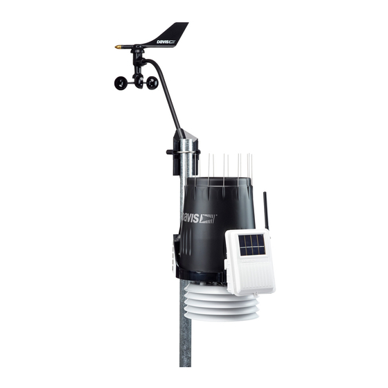
The Integrated Sensor Suite (ISS) collects outside weather data and sends the data to a Vantage Pro2 console or Weather Envoy. Wireless and cabled versions of the ISS are available, as well as standard and plus versions. The Wireless ISS is solar powered and sends data to the console via a low-power radio. - Page 4 Preparing the ISS for Installation Note: Some of the components pictured are available with the Vantage Pro2 Plus ISS model and do not come with the standard models. If the ISS is a plus model and contains the UV and solar radiation sensors, do not touch the small white diffusers on top of the sensors.
- Page 5 • Check the factory-installed sensor cable connections to the SIM. • Connect the anemometer sensor cable to the Sensor Interface Module (SIM). • Apply power to the ISS and test communication with the console. • Change the transmitter ID for wireless communication, if necessary. Assemble the Anemometer The anemometer measures wind direction and speed.
- Page 6 Preparing the ISS for Installation 4. Slide the tooth-lock washer and hex nut onto the machine screw. Tighten the hex nut while holding the screw with a Phillips head screwdriver to prevent it from turning. 5. Press the sensor cable firmly and completely into the zig-zagging channel in the base, starting from the arm and progressing downward to the bottom of the base.
- Page 7 Check SIM Sensor Connections The SIM is located in the housing on the front of the ISS station. The SIM contains all the connections for the weather sensors of the ISS. Check the SIM to ensure that all sensors are connected properly. Open the SIM Box 1.
- Page 8 Once the sensor connections have been checked and the anemometer cable has been inserted, a connection between the ISS and the Vantage Pro2 console must be made. 7. Read the following instructions that best apply to your ISS and Vantage Pro2 assem- bly: •...
-
Page 9: Cabled Iss Assembly
CONSOLE. Note: If you haven’t powered up the console yet, refer to the installation instructions in the Vantage Pro2 Console Manual and apply power to the console. 5. On the back of your console, insert the other end of the console cable into the modular receptacle labeled ISS. - Page 10 DIP switches. Note: If the LED is flashing rapidly, call Technical Support. See “Contacting Davis Instruments” on page 27 for more information. If the console is still not receiving readings, ensure that the console is in Setup Mode and reboot the console by disconnecting the AC power adapter from the console and removing the console batteries for at least 30 seconds.
-
Page 11: Wireless Iss Assembly
30 for locating the components and points of interest on the SIM board. Verifying Communication with the Console 1. Power the console if it does not already have power. Refer to the Vantage Pro2 Console Manual and apply power the console. - Page 12 5. Be sure to allow up to a minute for the ID number to display on the screen. Verifying Data from the ISS Sensors Use these steps to verify reception of ISS data at the wireless Vantage Pro2 console and to test the operation of the ISS sensors.
- Page 13 ID. The default transmitter ID is 1 for both the ISS and the Vantage Pro2 console, and should work fine for most situations. Change the transmitter ID if any of the following issues are true: •...
- Page 14 Use this table to ensure that each wireless transmitting station in the weather station system is broadcasting on its own transmitter ID. Set the Vantage Pro2 console to the same ID as the transmitters, as described in the Vantage Pro2 Console Manual.
-
Page 15: Preparing The Iss For Installation
Preparing the ISS for Installation Once all the sensors have been connected and communication between the ISS and the console has been successfully established, continue to prepare the ISS unit for installation. The steps for preparing the ISS for installation are as follows. •... - Page 16 Prepare the Rain Collector 2. Carefully cut and remove the plastic cable tie (usually black in color) that holds the tipping bucket in place during shipping. 3. On your console screen, look for DAILY RAIN display. If the console is cabled to the ISS, reconnect the cable to see if the console is receiving the rain read- ings.
- Page 17 Note: The above procedure converts the collector to 0.2 mm measurements. The console must be set accordingly. See the Vantage Pro2 Console Manual for more information. Locating the ISS and Anemometer For the weather station to perform at its best, use these guidelines to select the best mounting locations for the ISS and anemometer.
- Page 18 Keep the anemometer cable coiled if possible during the ISS and anemometer assembly so that it is easily stowed once installation is complete. • The Cabled Vantage Pro2 includes a 100' (30 m) cable to go between the console and the ISS. This can be extended up to 1000' (300 m) using optional cables. Anemometer...
- Page 19 If possible, align the pivot joints of both the ISS and the console antennas so that the are facing each other for maximum signal strength. • Turn the gain on to improve reception of a weak signal. Refer to the Vantage Pro2 Console Manual for information on setting the console gain. •...
- Page 20 4. Press and hold DONE to return to the normal screen when finished testing. Note: See the Troubleshooting section of the check wireless signal strength and for more information on troubleshooting reception problems. Vantage Pro2 Console Manual for information on how to...
-
Page 21: Installing The Iss
Installing the ISS The anemometer and the main part of the ISS can be installed either together as a single unit on a pole, or apart from each other. The main part of the ISS includes the rain collector, the temperature and humidity sensors, the radiation shield, and the SIM housing. -
Page 22: Installation Instructions
Installing the ISS on a Flat Surface Installation Instructions There are several ways to mount and install the ISS unit. The following are installation types that Davis Instruments recommends. Individual ISS locations and installations may vary. • Installing the ISS on a flat surface •... - Page 23 Option 2: Installing the Anemometer on a Post or Flat Surface 1. With a 3/16" (5 mm) drill bit, drill two holes approximately 2-1/8" (54 mm) apart. Use a carpenter’s level to ensure the holes will be level. 2. Insert the 1/4" x 3" lag screws through the flat washers and the holes in the anemome- ter mounting base into the post.
- Page 24 Installing the ISS on a Pole Guidelines for Installing the ISS on a Pole • When mounting both sides together, remember that whichever side of the ISS is mounted first, the U-bolt from the opposite side must also be placed around the pole before tightening the U-bolts.
-
Page 25: Finishing The Installation
Finishing the Installation Level the Solar and UV Sensors If you have a Vantage Pro2 Plus station that includes a solar or UV sensor, use the bubble level on the sensors as a guide to verify that the sensors are level. - Page 26 Using Extension Cables: Note: Not all cables are compatible with your Vantage Pro2 system. To be sure they will work, order Davis extension cables from your dealer or directly from Davis Instruments. The Anemometer can be extended further than 40’ from the ISS by using Davis Instruments extension cables, #7876.
-
Page 27: Maintenance And Troubleshooting
SIM before cleaning so that no inaccurate readings are logged, or clear the weather data that was logged on the Vantage Pro2 console after cleaning is complete. See your Vantage Pro2 Console Manual for instructions on clearing weather data. -
Page 28: Troubleshooting
Try removing and then re- installing the cable to correct the faulty connection. If the sensor still functions intermit- tently contact Technical Support. See “Contacting Davis Instruments” on page 27. Most Common Rain Collector Problem If the rain collector seems to be under-reporting rainfall, remove the rain collector cone to clean the tipping bucket and clear out any debris. - Page 29 Remove the wind cups (loosen the set screw) and clear out any bugs or debris. Turn the shaft the cups rotate on. If it feels gritty or stiff, contact Davis Technical Support.
-
Page 30: Appendices
Appendices Appendix A: Re-orienting the Wind Vane The Vantage Pro2 station is configured to register wind direction correctly if the anemometer points to true north. If the anemometer shaft can not be mounted to point to true north, use the following instructions to correct the wind vane orientation. - Page 31 Temperature range: ....-40 to 150° Fahrenheit (-40 to 65° Celsius) Power input: ..... Console Cable from Vantage Pro2 console Optional...
- Page 32 SIM Board Display and Contents SIM Board Display and Contents SENSOR SENSOR INTERFACE INTERFACE MODULE MODULE RAIN RAIN WIND WIND Power Tab Solar AC Adapter Socke Battery Socket Cabled Connection Transmitter ID DIP Switch Test DIP Switch TEMP TEMP Test LED Temperature/Humidity Sensor Connector Wind Sensor Connector Rain Sensor Connector...
Need help?
Do you have a question about the Vantage Pro2 and is the answer not in the manual?
Questions and answers